Karson T_type core Data
AM335x 处理器 SDK RTOS 板库端口和启动说明书

Board Porting\Bring up using Processor SDK RTOS for AM335xProcessor SDK RTOS component known as board library consolidates all the board-specific information so that all the modifications made when moving to a new custom platform using the SOC can be made in the source of this library.There are three different components in PRSDK that help in porting and bring up of a custom board:∙Board library updatesa.PLL Clocking and PRCMb.Pin mux Updatec.DDR Configurationd.Peripheral instances updates∙Diagnostics tests∙Boot loader updatesBoard Library Updates in Processor SDK RTOS:PLL ClockingThere are two places where the device PLL configurations are performed when using Processor SDK RTOS and CCS.Debug environment:Debug environment refers to development setup where code is debugged using JTAG emulator on the SOC. The PRSDK software relies on the GEL file that is part of the target configuration to setup the clocks and the DDR for the device. The CCS GEL file for AM335x platforms is located in the CCS package at the location ccsv7\ccs_base\emulation\boards\<boardName>For example for beagle bone black, the files can be found atccsv7\ccs_base\emulation\boards\beaglebone\gelThe GEL is the first piece of software that should be brought up on a custom board.Production environment:Production environment refers to the setup when the base application is booted from a boot media like a flash memory or host interface. In this environment, the bootloader sets performs all the SOC and board initialization and copies the application from flash memory to the device memory.The clock setup in the bootloader code can be located atpdk_am335x_x_x_x\packages\ti\starterware\bootloader\src\am335xUsers can choose to use the platform clocking similar to one of TI reference platforms or can modify them as per their application requirements. By default the PLL settings are setup for OPP_NOM settings (MPU= 600 MHz.)TI provides Clock Tree tool to allow users to simulate the clocking on the SOC. For quick reference of the multiplier and divider settings to change the PLL setting is provided in the spreadsheetAM335x_DPLL_CALCv3.xlsx.After modifying the clocking in the bootloader, users need to rebuild the bootloader using instructions provided in Processor_SDK_RTOS_BOOT_AM335x/AM437xPRCM Modules Enable:PRCM Module Enable is required to turn on the power domain and the clocking to each of the modules on the SOC. The PRCM Enable calls to enable each module are made from the functionBoard_moduleClockInit which is found in the location.pdk_am335x_1_0_9\packages\ti\board\src\bbbAM335x\bbbAM335x.cCheck every instance and peripheral required in the application platform and enable the module in the board library.For example to use three UARTs 0, 1 and 4, ensure that you have the following code as part of the board library setup:/* UART */status = PRCMModuleEnable(CHIPDB_MOD_ID_UART, 0U, 0U);status = PRCMModuleEnable(CHIPDB_MOD_ID_UART, 1U, 0U);status = PRCMModuleEnable(CHIPDB_MOD_ID_UART, 4U, 0U);Note: PRCMEnable function is defined in pdk_am335x_1_0_9\packages\ti\starterware\soc\am335x Pinmux updates in the Board library:Generating a New PinMux Configuration Using the PinMux Utility: This procedure uses the cloud-based pinmux utilityNavigate to ${PDK_INSTALL_DIR}\packages\ti\starterware\tools\pinmux_config\am335x and Load beaglebone_black_configAdd and remove peripheral instances and select the appropriate use cases required for development based on the application platform requirements and resolve all conflicts.Refer Pin_Mux_Utility_for_ARM_MPU_ProcessorsPost Processing steps:1.Change the Category filter to starterware and download the pinmux files am335x_pimnmux.hand am335x_pinmux_data.c2.At the bottom of am335x_pinmux.h change extern pinmuxBoardCfg_t gAM335xPinmuxData[];to extern pinmuxBoardCfg_t gBbbPinmuxData[];3.Change am335x_pinmux_data.c to am335x_beagleboneblack_pinmux_data.c.4.Change gAM335xPinmuxData to gBbbPinmuxData at the end of the file in file5.am335x_beagleboneblack_pinmux_data.c.Replace the existing files with the new files and rebuild the board library using the instructions in the section Rebuilding board Library in Processor SDK RTOS:Updating DDR settings:Similar to clock and PLL settings, DDR initialization is configured in the Debug environment through GEL files and in production environment using bootloader source files.TI provides AM335x_EMIF_Configuration_tips which contains a spreadsheet to enter the timing from the DDR datasheet to compute the EMIF timing number required to initialize DDR.We strongly recommend changing the value and testing using GEL files before using them in the bootloader software. For Sanity test, you can perform read/write tests using CCS Memory Browser or run the diagnostic memory read/write test that we provide in diagnostics package here:PDK_INSTALL_PATH\packages\ti\board\diag\memOnce the DDR timings have been confirmed, you can use the settings in the file:PDK_INSTALL_PATH \packages\ti\starterware\bootloader\src\am335x\sbl_am335x_platform_ddr.c Peripheral initialization:The board library is responsible for most of the SOC initialization but it also setup some board level components such as ethernet PHY and debug UART and I2C for reading board ID from EEPROM. All of the other peripheral instances and initialization needs to be done from the application level.For example for beagleboneblack, the peripheral initialization are performed from the source filepdk_am335x_1_0_9\packages\ti\board\src\bbbAM335x\bbbAM335x_lld_init.cThe debug UART instance, I2C Addresses are set using the file board_cfg.h found under:pdk_am335x_1_0_9\packages\ti\board\src\bbbAM335x\includeDefault UART instance is set to 0 in the board library. The Board initialization will configure the UART instance 0 to send binary log data to serial console using the Board_UARTInit function. If you wish to use more UART instances then we recommend linking in the UART driver in the application and using UART_open() and UART_stdioInit API calls from the application.Each peripheral driver in the Processor SDK RTOS has a SOC configuration that provides the interrupt numbers, base address, EDMA channels which can be updated using the file <peripheral>_soc.c file. This is used as default setup for initializing the driver instance. It can be overridden from the application using peripheral_getSOCInitCfg() and peripheral_setSOCInitCfg()For Example: All instances of UART for AM335x have been mapped in the filepdk_am335x_1_0_9\packages\ti\drv\uart\soc\am335x\UART_soc.cSystem integrators need to ensure that no interrupt numbers and EDMA resource conflicts exist in the SOC configuration for all drivers used in the system.To exercise three UARTs in the system, users can use the following code://Setup Debug UARTboardCfg = BOARD_INIT_PINMUX_CONFIG |BOARD_INIT_MODULE_CLOCK |BOARD_INIT_UART_STDIO;Board_init(boardCfg);// Open Additional UART Instances:/* UART SoC init configuration */UART_initConfig(false);/* Initialize the default configuration params. */UART_Params_init(&uartParams);// Open UART Instance 1uartTestInstance =1;uart1 = UART_open(uartTestInstance, &uartParams);//Open UART Instance 4uartTestInstance = 4;uart4 = UART_open(uartTestInstance, &uartParams);BoardID Detect:TI supports multiple evaluation and reference platforms for AM335x hence the hardware platforms are populated with an EEPROM which contains information that identifies the hardware and its revision. The board library and software components read the boardID and initialize the platform based on the boardID. The BoardID_detect function can be found in the source in the file bbbAM335x_info.c in the board library and board_am335x.c in the bootloader source at:<PDK_INSTALL_PATH>\packages\ti\starterware\board\am335xRebuilding board Library in Processor SDK RTOS:While Creating a new folder for the custom board is an option users can explore, TI recommends that users make there changes in existing board package using either bbbAM335x, evmAM335x oriceAM335x folder to avoid spending additional effort to modify the build files for including the customBord.Once all the update to the board library are completed, the board library can be updated using the following instructions.Instructions to rebuild board library:Setup Processor SDK build environment before following steps provided below.cd pdk_am335x_1_0_9\packagesgmake board_libFor a specific board users are required to provide the LIMIT_BOARDS argument.LIMIT_BOARDS : evmAM335x icev2AM335x iceAMIC110 bbbAM335x skAM335xFor Example for beagleboneblack, users can use the following build option:gmake board_lib LIMIT_BOARDS=bbbAM335xDiagnostics:After the board library is built, we highly recommend that you create a diagnostics package similar to one provided in board library to test different interfaces functionally during board bring up.The diagnostics package can be located at pdk_am335x_1_0_9\packages\ti\board\diag. These are simple bare-metal tests that use peripheral drivers to help functionally validate the pins and interfaces.Documentation for all available diagnostic tests is provided here:/index.php/Processor_SDK_RTOS_DIAGBootloader in Processor SDK RTOS:As part of the production flow, users are required to develop/port flashing and booting utilities so the application can be launched on the custom board with JTAG. TI provides a bootloader mechanism where the ROM bootloader loads a secondary bootloader on the onchip memory that initializes the SOC and DDR and then copies the application into DDR memory.The boot process and flashing tools have been described in detail in the following article that is part of processor SDK RTOS Software developer`s guide:/index.php/Processor_SDK_RTOS_BOOT_AM335x/AM437x#Building_the_B ootloader。
德尔·艾美 S5148F-ON 25GbE 顶层架(ToR)开放网络交换机说明书

The Dell EMC S5148 switch is an innovative, future-ready T op-of-Rack (T oR) open networking switch providing excellent capabilities and cost-effectiveness for the enterprise, mid-market, Tier2 cloud and NFV service providers with demanding compute and storage traffic environments.The S5148F-ON 25GbE switch is Dell EMC’s latest disaggregated hardware and software data center networking solution that provides state-of-the-art data plane programmability, backward compatible 25GbE server port connections, 100GbE uplinks, storage optimized architecture, and a broad range of functionality to meet the growing demands of today’s data center environment now and in the future.The compact S5148F-ON model design provides industry-leading density with up to 72 ports of 25GbE or up to 48 ports of 25GbE and 6 ports of 100GbE in a 1RU form factor.Using industry-leading hardware and a choice of Dell EMC’s OS10 or select 3rd party network operating systems and tools, the S5148F-ON Series offers flexibility by provision of configuration profiles and delivers non-blocking performance for workloads sensitive to packet loss. The compact S5148F-ON model provides multi rate speedenabling denser footprints and simplifying migration to 25GbE server connections and 100GbE fabrics.Data plane programmability allows the S5148F-ON to meet thedemands of the converged software defined data center by offering support for any future or emerging protocols, including hardware-based VXLAN (Layer 2 and Layer 3 gateway) support. Priority-based flow control (PFC), data center bridge exchange (DCBX) and enhanced transmission selection (ETS) make the S5148F-ON an excellent choice for DCB environments.The Dell EMC S5148F-ON model supports the open source Open Network Install Environment (ONIE) for zero touch installation of alternate network operating systems.Maximum performance and functionalityThe Dell EMC Networking S-Series S5148F-ON is a high-performance, multi-function, 10/25/40/50/100 GbE T oR switch purpose-built for applications in high-performance data center, cloud and computing environments.In addition, the S5148F-ON incorporates multiple architectural features that optimize data center network flexibility, efficiency, and availability, including IO panel to PSU airflow or PSU to IO panel airflow for hot/Key applications •Organizations looking to enter the software-defined data center era with a choice of networking technologies designed to deliver the flexibility they need• Use cases that require customization to any packet processing steps or supporting new protocols• Native high-density 25 GbE T oR server access in high- performance data center environments• 25 GbE backward compatible to 10G and 1G for future proofing and data center server migration to faster uplink speeds. • Capability to support mixed 25G and 10G servers on front panel ports without any limitations• iSCSI storage deployment including DCB converged lossless transactions• Suitable as a T oR or Leaf switch in 100G Active Fabric implementations• As a high speed VXLAN L2/L3 gateway that connects the hypervisor-based overlay networks with non-virtualized • infrastructure•Emerging applications requiring hardware support for new protocolsKey features •1RU high-density 25/10/1 GbE T oR switch with up to forty eight ports of native 25 GbE (SFP28) ports supporting 25 GbE without breakout cables• Multi-rate 100GbE ports support 10/25/40/50 GbE• 3.6 Tbps (full-duplex) non-blocking, cut-through switching fabric delivers line-rate performance under full load**• Programmable packet modification and forwarding • Programmable packet mirroring and multi-pathing • Converged network support for DCB and ECN capability • IO panel to PSU airflow or PSU to IO panel airflow • Redundant, hot-swappable power supplies and fans • IEEE 1588v2 PTP hardware supportDELL EMC NETWORKING S5148F-ON SERIES SWITCHProgrammable high-performance open networking top-of-rack switch with native 25Gserver ports and 100G network fabric connectivity• FCoE transit (FIP Snooping)• Full data center bridging (DCB) support for lossless iSCSI SANs, RoCE and converged network.• Redundant, hot-swappable power supplies and fans• I/O panel to PSU airflow or PSU to I/O panel airflow(reversable airflow)• VRF-lite enables sharing of networking infrastructure and provides L3 traffic isolation across tenants• 16, 28, 40, 52, 64 10GbE ports availableKey features with Dell EMC Networking OS10• Consistent DevOps framework across compute, storage and networking elements• Standard networking features, interfaces and scripting functions for legacy network operations integration• Standards-based switching hardware abstraction via Switch Abstraction Interface (SAI)• Pervasive, unrestricted developer environment via Control Plane Services (CPS)• Open and programmatic management interface via Common Management Services (CMS)• OS10 Premium Edition software enables Dell EMC layer 2 and 3 switching and routing protocols with integrated IP Services,Quality of Service, Manageability and Automation features• Platform agnostic via standard hardware abstraction layer (OCP-SAI)• Unmodified Linux kernel and unmodified Linux distribution• OS10 Open Edition software decoupled from L2/L3 protocol stack and services• Leverage common open source tools and best-practices (data models, commit rollbacks)• Increase VM Mobility region by stretching L2 VLAN within or across two DCs with unique VLT capabilities• Scalable L2 and L3 Ethernet Switching with QoS, ACL and a full complement of standards based IPv4 and IPv6 features including OSPF, BGP and PBR• Enhanced mirroring capabilities including local mirroring, Remote Port Mirroring (RPM), and Encapsulated Remote Port Mirroring(ERPM).• Converged network support for DCB, with priority flow control (802.1Qbb), ETS (802.1Qaz), DCBx and iSCSI TLV• Rogue NIC control provides hardware-based protection from NICS sending out excessive pause frames48 line-rate 25 Gigabit Ethernet SFP28 ports6 line-rate 100 Gigabit Ethernet QSFP28 ports1 RJ45 console/management port with RS232signaling1 Micro-USB type B optional console port1 10/100/1000 Base-T Ethernet port used asmanagement port1 USB type A port for the external mass storage Size: 1 RU, 1.72 h x 17.1 w x 18.1” d (4.4 h x 43.4 w x46 cm d)Weight: 22lbs (9.97kg)ISO 7779 A-weighted sound pressure level: 59.6 dBA at 73.4°F (23°C)Power supply: 100–240 VAC 50/60 HzMax. thermal output: 1956 BTU/hMax. current draw per system:5.73A/4.8A at 100/120V AC2.87A/2.4A at 200/240V ACMax. power consumption: 516 Watts (AC)T yp. power consumption: 421 Watts (AC) with all optics loadedMax. operating specifications:Operating temperature: 32° to 113°F (0° to 45°C) Operating humidity: 5 to 90% (RH), non-condensingFresh Air Compliant to 45CMax. non-operating specifications:Storage temperature: –40° to 158°F (–40° to70°C)Storage humidity: 5 to 95% (RH), non-condensingRedundancyHot swappable redundant power suppliesHot swappable redundant fansPerformanceSwitch fabric capacity: 3.6TbpsPacket buffer memory: 16MBCPU memory: 16GBMAC addresses: Up to 512KARP table: Up to 256KIPv4 routes: Up to 128KIPv6 routes: Up to 64KMulticast hosts: Up to 64KLink aggregation: Unlimited links per group, up to 36 groupsLayer 2 VLANs: 4KMSTP: 64 instancesLAG Load Balancing: User Configurable (MAC, IP, TCP/UDPport)IEEE Compliance802.1AB LLDPTIA-1057 LLDP-MED802.1s MSTP802.1w RSTP 802.3ad Link Aggregation with LACP802.3ae 10 Gigabit Ethernet (10GBase-X)802.3ba 40 Gigabit Ethernet (40GBase-X)802.3i Ethernet (10Base-T)802.3u Fast Ethernet (100Base-TX)802.3z Gigabit Ethernet (1000BaseX)802.1D Bridging, STP802.1p L2 Prioritization802.1Q VLAN T agging, Double VLAN T agging,GVRP802.1Qbb PFC802.1Qaz ETS802.1s MSTP802.1w RSTPPVST+802.1X Network Access Control802.3ab Gigabit Ethernet (1000BASE-T) orbreakout802.3ac Frame Extensions for VLAN T agging802.3ad Link Aggregation with LACP802.3ae 10 Gigabit Ethernet (10GBase-X)802.3ba 40 Gigabit Ethernet (40GBase-SR4,40GBase-CR4, 40GBase-LR4, 100GBase-SR10,100GBase-LR4, 100GBase-ER4) on optical ports802.3bj 100 Gigabit Ethernet802.3u Fast Ethernet (100Base-TX) on mgmtports802.3x Flow Control802.3z Gigabit Ethernet (1000Base-X) with QSAANSI/TIA-1057 LLDP-MEDJumbo MTU support 9,416 bytesLayer2 Protocols4301 Security Architecture for IPSec*4302 I PSec Authentication Header*4303 E SP Protocol*802.1D Compatible802.1p L2 Prioritization802.1Q VLAN T agging802.1s MSTP802.1w RSTP802.1t RPVST+802.3ad Link Aggregation with LACPVLT Virtual Link TrunkingRFC Compliance768 UDP793 TCP854 T elnet959 FTP1321 MD51350 TFTP2474 Differentiated Services2698 T wo Rate Three Color Marker3164 Syslog4254 SSHv2791 I Pv4792 ICMP826 ARP1027 Proxy ARP1035 DNS (client)1042 Ethernet Transmission1191 Path MTU Discovery1305 NTPv41519 CIDR1812 Routers1858 IP Fragment Filtering2131 DHCP (server and relay)5798 VRRP3021 31-bit Prefixes3046 DHCP Option 82 (Relay)1812 Requirements for IPv4 Routers1918 Address Allocation for Private Internets2474 Diffserv Field in IPv4 and Ipv6 Headers2596 Assured Forwarding PHB Group3195 Reliable Delivery for Syslog3246 Expedited Assured Forwarding4364 VRF-lite (IPv4 VRF with OSPF andBGP)*General IPv6 Protocols1981 Path MTU Discovery*2460 I Pv62461 Neighbor Discovery*2462 Stateless Address AutoConfig2463 I CMPv62464 Ethernet Transmission2675 Jumbo grams3587 Global Unicast Address Format4291 IPv6 Addressing2464 Transmission of IPv6 Packets overEthernet Networks2711 IPv6 Router Alert Option4007 IPv6 Scoped Address Architecture4213 Basic Transition Mechanisms for IPv6Hosts and Routers4291 IPv6 Addressing Architecture5095 Deprecation of T ype 0 Routing Headers inI Pv6IPv6 Management support (telnet, FTP, TACACS,RADIUS, SSH, NTP)OSPF (v2/v3)1587 NSSA1745 OSPF/BGP interaction1765 OSPF Database overflow2154 MD52328 OSPFv22370 Opaque LSA3101 OSPF NSSA3623 OSPF Graceful Restart (Helper mode)*BGP 1997 Communities 2385 MD52439 Route Flap Damping 2796 Route Reflection 2842 Capabilities 2918 Route Refresh 3065 Confederations 4271 BGP-44360 Extended Communities 4893 4-byte ASN5396 4-byte ASN Representation 5492Capabilities AdvertisementLinux Distribution Debian Linux version 8.4Linux Kernel 3.16MIBSIP MIB– Net SNMPIP Forward MIB– Net SNMPHost Resources MIB– Net SNMP IF MIB – Net SNMP LLDP MIB Entity MIB LAG MIBDell-Vendor MIBTCP MIB – Net SNMP UDP MIB – Net SNMP SNMPv2 MIB – Net SNMP Network Management SNMPv1/2SSHv2FTP, TFTP, SCP SyslogPort Mirroring RADIUS 802.1XSupport Assist (Phone Home)Netconf APIs XML SchemaCLI Commit (Scratchpad)AutomationControl Plane Services APIs Linux Utilities and Scripting Tools Quality of Service Access Control Lists Prefix List Route-MapRate Shaping (Egress)Rate Policing (Ingress)Scheduling Algorithms Round RobinWeighted Round Robin Deficit Round Robin Strict PriorityWeighted Random Early Detect Security 2865 RADIUS 3162 Radius and IPv64250, 4251, 4252, 4253, 4254 SSHv2Data center bridging802.1QbbPriority-Based Flow Control802.1Qaz Enhanced Transmission Selection (ETS)*Data Center Bridging eXchange(DCBx) DCBx Application TLV (iSCSI, FCoE*)Regulatory compliance SafetyUL/CSA 60950-1, Second Edition EN 60950-1, Second EditionIEC 60950-1, Second Edition Including All National Deviations and Group DifferencesEN 60825-1 Safety of Laser Products Part 1: EquipmentClassification Requirements and User’s GuideEN 60825-2 Safety of Laser Products Part 2: Safety of Optical Fibre Communication Systems FDA Regulation 21 CFR 1040.10 and 1040.11Emissions & Immunity EMC complianceFCC Part 15 (CFR 47) (USA) Class A ICES-003 (Canada) Class AEN55032: 2015 (Europe) Class A CISPR32 (International) Class AAS/NZS CISPR32 (Australia and New Zealand) Class AVCCI (Japan) Class A KN32 (Korea) Class ACNS13438 (T aiwan) Class A CISPR22EN55022EN61000-3-2EN61000-3-3EN61000-6-1EN300 386EN 61000-4-2 ESDEN 61000-4-3 Radiated Immunity EN 61000-4-4 EFT EN 61000-4-5 SurgeEN 61000-4-6 Low Frequency Conducted Immunity NEBSGR-63-Core GR-1089-Core ATT -TP-76200VZ.TPR.9305RoHSRoHS 6 and China RoHS compliantCertificationsJapan: VCCI V3/2009 Class AUSA: FCC CFR 47 Part 15, Subpart B:2009, Class A Warranty1 Year Return to DepotLearn more at /Networking*Future release**Packet sizes over 147 BytesIT Lifecycle Services for NetworkingExperts, insights and easeOur highly trained experts, withinnovative tools and proven processes, help you transform your IT investments into strategic advantages.Plan & Design Let us analyze yourmultivendor environment and deliver a comprehensive report and action plan to build upon the existing network and improve performance.Deploy & IntegrateGet new wired or wireless network technology installed and configured with ProDeploy. Reduce costs, save time, and get up and running cateEnsure your staff builds the right skills for long-termsuccess. Get certified on Dell EMC Networking technology and learn how to increase performance and optimize infrastructure.Manage & SupportGain access to technical experts and quickly resolve multivendor networking challenges with ProSupport. Spend less time resolving network issues and more time innovating.OptimizeMaximize performance for dynamic IT environments with Dell EMC Optimize. Benefit from in-depth predictive analysis, remote monitoring and a dedicated systems analyst for your network.RetireWe can help you resell or retire excess hardware while meeting local regulatory guidelines and acting in an environmentally responsible way.Learn more at/Services。
core0 incorrect pattern readout

core0 incorrect pattern readout 是一个常见的错误信息,通常出现在仿真器或调试器中出现错误时。
这个错误信息通常意味着在读取存储器或寄存器时发生了错误,可能是因为地址、数据或控制信号的错误。
解决这个问题的方法取决于具体的上下文和情况,但以下是一些可能的解决步骤:
检查地址:确保您正在访问的地址是正确的,并且您有权访问该地址。
检查任何可能导致地址错误的因素,例如指针错误或数组越界。
检查数据:确保您正在写入或读取的数据是正确的,并且与您期望的数据类型匹配。
检查任何可能导致数据错误的因素,例如数据类型不匹配或数据溢出。
检查控制信号:确保控制信号(例如读/写信号)是正确的,并且与您期望的控制信号匹配。
检查任何可能导致控制信号错误的因素,例如控制信号时序不正确或控制信号逻辑错误。
检查仿真器或调试器设置:确保仿真器或调试器的设置是正确的,并且与您正在使用的开发板或芯片匹配。
检查任何可能导致设置错误的因素,例如仿真器或调试器版本不兼容或开发板配置不正确。
重新启动仿真器或调试器:有时候,重新启动仿真器或调试器可以解决一些未知的问题或冲突。
科瑞RFID配置文件
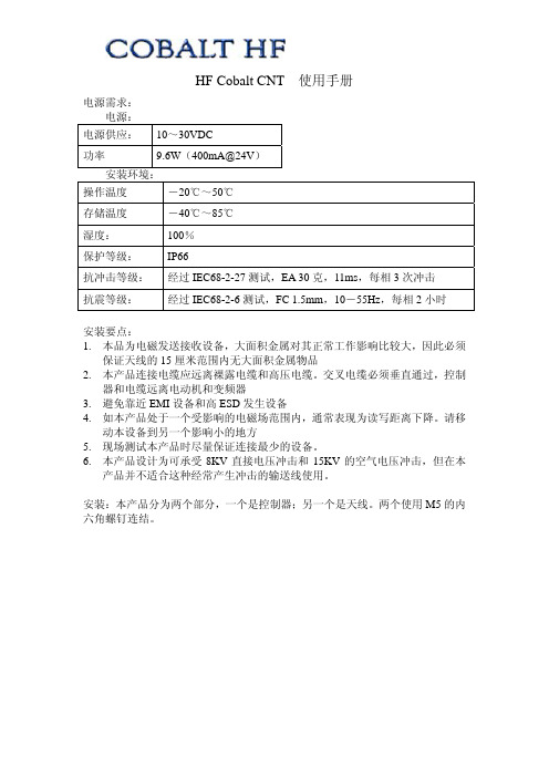
HF Cobalt CNT 使用手册电源需求:电源:电源供应: 10~30VDC功率 9.6W(400mA@24V)安装环境:操作温度-20℃~50℃存储温度-40℃~85℃湿度: 100%保护等级: IP66抗冲击等级:经过IEC68-2-27测试,EA 30克,11ms,每相3次冲击抗震等级:经过IEC68-2-6测试,FC 1.5mm,10-55Hz,每相2小时安装要点:1.本品为电磁发送接收设备,大面积金属对其正常工作影响比较大,因此必须保证天线的15厘米范围内无大面积金属物品2.本产品连接电缆应远离裸露电缆和高压电缆。
交叉电缆必须垂直通过,控制器和电缆远离电动机和变频器3.避免靠近EMI设备和高ESD发生设备4.如本产品处于一个受影响的电磁场范围内,通常表现为读写距离下降。
请移动本设备到另一个影响小的地方5.现场测试本产品时尽量保证连接最少的设备。
6.本产品设计为可承受8KV直接电压冲击和15KV的空气电压冲击,但在本产品并不适合这种经常产生冲击的输送线使用。
安装:本产品分为两个部分,一个是控制器;另一个是天线。
两个使用M5的内六角螺钉连结。
控制器下部有两个接口:左边借口为5针的标准DeviceNet接口右边为标准RS232串口DeviceNet接口针脚定义:定义1 接地GND2 电源正V+3 电源负V-4 CAN_H5 CAN_LRS232串口针脚定义定义1~5 未使用6 RX(连接计算机TX)7 TX(连接计算机RX)8 SGND(信号地)RS232连结图:配置:使用DeveceNet接口供应24V电压,读写器上电至自检完毕使用标准RS232电缆连接DNT的232口,并设置计算机的串口参数如下:设置值波特率(Baud) 9600字长(Data Bits) 8停止字符(Stop bit) 1Parity None握手(Handshaking) None使用EMS公司提供的配置软件Dashboard连接本读写器读写器模块网络状态指示灯:状态指示灯表示意义如下描述熄灭模块未在线或未上电常绿模块正常,DeviceNet网络正常绿色闪烁网络已经连接,但是需要PLC重新配置输入输出缓冲区红色闪烁可恢复性错误或网络连接超时常红不可恢复错误(通常为节点冲突)连接后界面如下本产品的默认DeveceNet配置如下=63=125K可在上图的右下角位置修改这两个选项PLC连接安装EDS文件004E00000BD60204.eds当DeviceNet模块扫描到DNT模块后,需要手动配置输入输出缓冲区。
hyperscan dpdk 命令 应用案例

Hyperscan是一个高性能的正则表达式匹配库,而DPDK(Data Plane Development Kit)是用于构建高性能数据平面应用程序的开源工具包。
将Hyperscan与DPDK结合使用可以用于各种网络和数据包处理应用。
以下是一些Hyperscan与DPDK结合使用的命令和应用案例示例:1. **构建Hyperscan与DPDK集成**:在构建DPDK应用程序时,需要确保Hyperscan库正确集成到DPDK中。
可以使用以下命令构建DPDK应用程序,其中`HS_DIR`是Hyperscan库的路径:```shellmake -C $RTE_SDK T=$RTE_TARGETmake -C $RTE_SDK T=$RTE_TARGET installexport RTE_SDK=$HS_DIR```2. **使用Hyperscan进行正则表达式匹配**:在DPDK应用程序中,你可以使用Hyperscan库进行高性能的正则表达式匹配,以实现各种应用,如网络流量分析、防火墙规则匹配、恶意软件检测等。
以下是一个简单的示例命令,演示如何在DPDK应用程序中使用Hyperscan进行正则表达式匹配:```c#include <rte.h>#include <rte_regexdev.h>#include <hs/hs.h>...// 初始化Hyperscan库hs_platform_info_t platform_info;hs_error_t err = hs_populate_platform(&platform_info);if (err != HS_SUCCESS) {// 处理错误}// 创建Hyperscan数据库和Scratch空间hs_database_t *db;hs_scratch_t *scratch;err = hs_compile("pattern1|pattern2", HS_FLAG_CASELESS,HS_MODE_BLOCK, NULL, &db, &scratch);if (err != HS_SUCCESS) {// 处理错误}...// 使用Hyperscan进行正则表达式匹配err = hs_scan(db, "input_data", input_length, 0, scratch, match_callback, NULL);if (err != HS_SUCCESS) {// 处理错误}// 释放资源hs_free_scratch(scratch);hs_free_database(db);...```3. **防火墙应用**:你可以使用DPDK和Hyperscan构建高性能的防火墙应用程序,通过正则表达式匹配检测网络流量中的恶意或不安全内容,并根据匹配结果采取相应的操作,如阻止或日志记录。
深圳拓普龙科技有限公司 5卡GPU服务器(ATX)机箱规格书说明书

使用手册5卡GPU服务器(ATX)机箱规格书文档版本:A0深圳拓普龙科技有限公司SHENZHEN TOPLOONG TECHNOLOGY CO., LTD目录目录 (1)1.1 产品类型 (2)1.2 产品简介 (2)1.3 产品特点 (2)1.4 产品规格 (3)1.5 GPU底板详解 (3)1.6 选购配件 (3)1.1产品类型4U 5卡机架式GPU服务器机箱1.2产品简介5卡GPU服务器机箱正视图5卡GPU服务器机箱后视图5卡GPU服务器俯视图5 卡 GPU服务器机箱尺寸为437.5mm(W)*780mm(D)*176.5mm(H),支持5张GPU,PCIE通道支持PCIE3.0 X16,机箱标配3个12038和2个8038滚珠风扇,具有良好的散热性能,机箱兼容12"*13"及以下尺寸的E-ATX/ATX主板,支持ATX电源,供电稳定可靠。
产品广泛应用于大数据、云计算、HPC、AI、渲染、深度学习、边缘计算等场景,在GPU运算性能、系统稳定性等方面表现出色,能最大程度的满足人工智能等新兴领域的开发与应用。
1.3产品特点✧良好的散热性能:3个12038滚珠风扇和2 个 8038 滚珠风扇提供了良好的散热条件✧底板兼容性强:PCIE槽间距81mm,支持 2080Ti/3060/3070/3080/3090/4080 等主流GPU✧稳定的供电设计:支持ATX电源,供电稳定可靠1.4产品规格:1.5GPU底板详解GPU 底板尺寸为 400mm*205mm,设计有 5 个 PCIE3.0X16 插槽,槽间距 81mm,PCIE 通道采用SlimSAS 3.0(SFF8654 8x)连接器,具备高带宽低损耗的特点,兼容2080Ti/3060/3070/3080/3090/4080 等型号的 GPU。
GPU底板PCIE转接卡GPU 底板尺寸图1.6选购配件。
TestOS移植K210开发板
TestOS移植K210开发板概述本⽂介绍前六个部分在移植K210开发板遇到的问题,第七章⽐较⿇烦,就放弃了。
这⾥选⽤的原因是提供了K210的使⽤教程,同时也提供了相应的适配,使得我能够在⼏乎不改变内核代码的情况下进⾏移植,所以还是感谢rCore教程的作者、RustSBI的作者洛佳⼤佬以及借我开发板的ccc⼤佬。
内容第⼀部分第⼀部分没什么需要修改的,主要是学习开发板的使⽤。
⾸先将开发板使⽤Type-C的数据线连上电脑。
由于我编译和烧录使⽤的是虚拟机,所以需要映射USB端⼝,VirtualBox启动系统后窗⼝右下⾓有个USB的图标,右键点击,选择那个中⽂拼⾳的端⼝打上勾,就映射成功了。
然后下载,把项⽬⾥的kflash.py下载下来。
为了获得K210的输出信息,需要安装串⼝通信的Python库:pip3 install pyserial修改makefile:rustsbi-k210_size := 131072k210_serialport := /dev/ttyUSB0k210:riscv64-unknown-elf-gcc os.c printf.c entry.S -T linker_k210.ld -ffreestanding -nostdlib -g -o os_k210 -mcmodel=medanyriscv64-unknown-elf-objcopy os_k210 --strip-all -O binary os_k210.bin@cp rustsbi-k210.bin rustsbi-k210.copy@dd if=os_k210.bin of=rustsbi-k210.copy bs=$(rustsbi-k210_size) seek=1@mv rustsbi-k210.copy os_k210.bin@sudo chmod 777 $(k210_serialport)python3 kflash.py -p $(k210_serialport) -b 1500000 os_k210.binpython3 -m serial.tools.miniterm --eol LF --dtr 0 --rts 0 --filter direct $(k210_serialport) 115200除了编译之外,需要建⽴⼀个⼆进制映像⽂件,包含rustsbi-k210.bin和编译出的os_k210.bin。
NORITAKE-ITRON GU256x128C-3900 DATA SHEET
1F 01
Vertical Scroll Mode
1F 02
Horizontal Scroll Mode
1F 03
Cursor Set
1F 24
RAM Macro Processing
1F 3A
Display Brightness
1F 58
Macro Execution
1F 5E
Enable/Disable Reverse Disply 1F 72
¾ Download Char. Definition +26
¾ Delete Download Character +3F
¾ Initialize Display
+40
¾ Define International Font
+52
¾ Define Char. Code Type
+74
Overwrite Mode
Parameter
Symbol Value
Condition
Power Supply Voltage
VCC
5.0VDC +/- 5% GND=0V
Power Supply Current
ICC
850mADC typ.
Vcc=5V
RS232 Serial High Input VIH
3.0VDC min.
Controller
Flash ROM RAM
DC/DC Converter
DISPLAY ADDRESS SELECT SW1 SW2 SW3 SW4 Address OFF OFF OFF OFF 00H ON OFF OFF OFF 01H OFF ON OFF OFF 02H ON ON OFF OFF 03H OFF OFF ON OFF 04H ON OFF ON OFF 05H OFF ON ON OFF 06H ON ON ON OFF 07H OFF OFF OFF ON 08H ON OFF OFF ON 09H OFF ON OFF ON 0AH ON ON OFF ON 0BH OFF OFF ON ON 0CH ON OFF ON ON 0DH OFF ON ON ON 0EH ON ON ON ON 0FH
tcgetattr函数源码
tcgetattr函数源码
tcgetattr是Unix-like 系统中用于获取终端(通常是一个tty 设备)当前设置的函数。
这个函数是termios 库的一部分,该库提供了对POSIX 终端I/O 功能的访问。
tcgetattr函数的原型如下:c
int tcgetattr(int fd, struct termios *termios_p);
fd是一个打开的文件描述符,通常指向一个tty 设备。
termios_p是一个指向termios结构的指针,该结构用于存储终端的属性。
tcgetattr函数的源代码并不是单独的一个文件,而是作为操作系统或libc 库的一部分。
例如,在GNU C Library (glibc) 中,tcgetattr的实现会涉及多个文件和内部函数。
由于tcgetattr是系统调用的一部分,其实现通常涉及内核级别的代码。
在Linux 中,系统调用的实现位于内核源代码中,而不是libc 库中。
但是,glibc 会提供一个包装函数,这样用户空间程序就可以通过这个包装函数来调用系统调用。
如果你想查看tcgetattr的具体实现,你需要查看你使用的libc 库的源代码,或者查看你的操作系统的内核源代码(对于系统调用部分)。
例如,在glibc 的源代码中,你可以在sysdeps/unix/syscall-template.S或类似的文件中找到系统调用的包
装函数,但是具体的实现会在内核中。
对于Linux 内核,你可以在drivers/tty/tty_io.c或附近的文件中查找相关代码。
注意:直接阅读和理解这些源代码可能需要一定的 C 语言知识和对操作系统内部工作原理的了解。
g_initable_new 说明
g_initable_new 说明通过g_initable_new 方法来创建新的对象是一种常见的做法。
这种方法在GLib库中定义,其主要作用是在对象的初始化阶段调用指定的函数。
本文将详细介绍g_initable_new方法的说明,包括其原理、使用方法以及示例代码。
## g_initable_new的原理g_initable_new是GLib库提供的一个函数,其主要作用是创建一个新的对象并在初始化阶段调用指定的初始化函数。
该函数的原型如下:```cgpointer g_initable_new (GType object_type, GCancellable *cancellable, GError **error, const gchar *first_property_name, ...);```上述函数的参数说明如下:- **object_type**:对象的类型,使用GType数据类型表示。
- **cancellable**:可选参数,可以传递一个GCancellable对象,用于取消操作。
- **error**:可选参数,用于传递错误信息。
- **first_property_name**:可选参数,用于以属性名称-属性值对的形式指定对象的属性。
g_initable_new函数的返回值是创建的新对象的指针。
## g_initable_new的使用方法使用g_initable_new函数创建新对象的一般步骤如下:1. 导入GLib头文件。
2. 定义一个指向要创建对象的指针变量。
3. 使用g_initable_new函数创建新对象。
4. 检查错误,并处理异常情况。
5. 使用创建的对象进行后续操作。
6. 释放资源。
下面是一个简单的示例代码:```c#include <glib.h>int main() {GType obj_type = G_TYPE_OBJECT;GObject *new_obj = NULL;GError *error = NULL;// 使用g_initable_new函数创建新对象new_obj = g_initable_new(obj_type, NULL, &error, NULL);if (new_obj == NULL) {g_print("创建对象失败: %s\n", error->message);g_error_free(error);return 1;}// 对象创建成功,可以进行后续操作// ...// 释放资源g_object_unref(new_obj);return 0;}```在上述示例代码中,首先导入了GLib库的头文件。
- 1、下载文档前请自行甄别文档内容的完整性,平台不提供额外的编辑、内容补充、找答案等附加服务。
- 2、"仅部分预览"的文档,不可在线预览部分如存在完整性等问题,可反馈申请退款(可完整预览的文档不适用该条件!)。
- 3、如文档侵犯您的权益,请联系客服反馈,我们会尽快为您处理(人工客服工作时间:9:00-18:30)。
Color
Gray T.B.D.
Red T.B.D. T.B.D. T.B.D. T.B.D. Green Yellow T.B.D. Drak Blue KQ Gray T.B.D. T.B.D. Grass Green Black Blue
AL Tolerance
±5% ±5% ±10% ±5% ±10% ±10% ±5% ±10% ±10% ±10% ±10% ±10% ±10% ±10% ±10% ±10% ±10%
PLAIN CORES
PXX24-PXX40 PX48-PXX76
A
B
±0.25 ±0.55
±0.38 ±0.38
±0.38 ±0.76
±0.76 ±0.76
OD L
+0/-0.13 ±0.38
+0/-0.13 ±0.5
C
±0.13 ±0.18 ±0.25 ±0.18
D
±0.18 ±0.25 ±0.25 ±0.5
-26 Material & -26-200 Material The most popular material.It is a costeffective general purpose material that is usefull in a wide variety of power conversion and lin filter applications.
E
±0.13 ±0.18 ±0.18 ±0.18
G
±0.18 ±0.25 ±0.25 ±0.5
Magnetic tolerance
Typical AL Tolerance
-2
-8
-14
-18
-26
-28
-33
-38
-40
-45
-52
-2-200 -8-200 -14-200 -18-200 -26-200 -28-200 -33-200 -38-200 -40-200 -45-200 -52-200
Karson(Company code) Core type OD(inches) Material 200℃ Series
Magnetic dimensions
Karson Prat No
-125
-200
KST16-2
KST16-2-200
KST16-6
KST16-6-200
KST16-8/90
KST16-8/90-200
KST249-KST400
±0.5 ±0.5 ±0.64
A
B
D
E
L
±0.4 ±0.5 ±0.13 ±0.13 ±0.5
OD
±0.64 ±0.76
ID
±0.64 ±0.76
HT
±0.76 ±0.76
E CORES
KSE49-KSE118 KSE125-KSE162 KSE168-KSE225 KSE305-KSE450
KST16-10
KST16-10-200
KST16-15
Black Green/Blue
Material Mix No -2-200 -6-200 -8-200 -10-200 -14-200 -15-200 -17-200 -18-200 -26-200 -28-200 -33-200 -34-200 -35-200 -38-200 -40-200 -45-200 -52-200
△
△
△
△
△
△
△
△
△
△
△
△
△
△
△
△
△
△
△
△
△
△
△
△
△
△
△
△
△
△
Material description
-2/14 Materials &-2/14-200 Materials The low permeability of these materials will result in lower operating AC flux density than with other materials with no additional gap-loss,The -14 material is similar to -2 material with slightly higher permeability.
-33 Material & -33-200 Material The good linerity,low cost,and relatively low Permeability of this material make it popular in large sizes for high power UPS chokes.
Initial Permeability
10 8.5 35 6 14 25 4 55 75 22 33 33 33 85 60 100 75
Temp coef of Permeability
94 35 370 145 150 190 50 385 825 415 635 565 666 956 950 1040 650
Material applications
Typical
Light Dimmer Chokes EMI Line Chokes
DC Chokes<50KHz DC Chokes≥50KHz Power Factor correction
Chockes<50KHz Power Factor correction
-38 Material & -38-200 Material A higher permeability alternate to the -26 material. A low cost material best used at line frequency.
-40 Material & -40-200 Material The least expensive material. It has characteristics quite similar to the very popular -26 material. Popular in large sizes.
-34/35 Materials & -34/35-200 Material An inexpensive alternate to the -8 material for applications where high frequency core loss is not critical.Good linearity with high bias.
TOROIDAL CORE
Dimensional tolerance(mm)
Color code
-2 Red/Gray -8 Yellow/Red -18 Green/Red -26 Yellow/White -28 Gray/Green -33 Gray/Yellow -38 Gray/Black -40 Green/Yellow -45 Black/Black -52 Green/Blue
Practical Frequency/range 250KHz-10MHz
3MHz-40MHz 20KHz-1MHz 15MHz-100MHz 500KHz-15MHz 150KHz-3MHz 20MHz-200MHz 10KHz-1MHz 1KHz-500KHz 50KHz-100KHz 20KHz-5MHz 20KHz-5MHz 20KHz-5MHz 1KHz-500KHz 1KHz-1MHz 1KHz-500KHz 1KHz-1MHz
MATERIAL
Karson material properties
Material Mix No
-2 -6 -8 -10 -14 -15 -17 -18 -26 -28 -33 -34 -35 -38 -40 -45 -52
Color/Code
Red/Gray Yellow/Gray Yellow/Red Black/Gray Black/Red Red/White Blue/Yellow Green/Red Yellow/White Gray/Green Gray/Yellow Gray/Blue Yellow/Gray Gray/Black Green/Yellow
The toroidal cores are tested with an evenly-spaced full single-layer winding in order to minimize leakage effects.Iron powder cores tested with a small number of turns which are not evenly distributed will produce higher inductance readings than expected. The E cores are tested with 100 turns.
-8 Material & -8-200 Material This material has low core loss and good linearity under high bias conditions,a good high frequency material,while the highest cost material.
TOLERANCES
Dimensional tolerance(mm)
Toroids
KST16-KST20 KST25-KST72 KST80-KST141
BUS BAR
KSHS300-KSHS400