fsr压力传感器技术手册
安控科技 无线压力传感器 说明书

无线压力传感器使用手册(第二版)一、 外型二、 主要功能✓自动测量压力值。
✓自带液晶显示器及键盘。
✓远程修改工作参数﹙主动上传数据﹚。
✓锂电池供电。
三、 特点1.设备简单,只有一个与传统压力变送器相似的终端组成。
2.安装方便,与传统的压力变送器安装方法相同。
3.使用方便,自带液晶显示器及按键,可以随时读值及修改参数。
4.运行稳定,使用电池供电,可消除外界电网干扰。
5.技术先进,采用了先进的ZigBee技术。
四、 主要技术指标1.压力测量精度0.5%2.压力测量范围0~25MPa/0~35MPa3.工作温度范围-40 ~ 70℃4.液晶显示温度-20 ~ 50℃5.工作湿度范围 5 ~ 95%6.工作电压 3.6V7.采用IEEE802.15.4通讯模式 2.4GHz多频/多址8.数据传输距离(空旷距离)30米9.最大功耗1mW10.接收灵敏度-100dBm11.重量<1.5kg12.外型尺寸见下图五、 型号说明SZ903测压范围0-25 MPaSZ905测压范围0-35 MPa1六、 安装● 检查无线压力变送器,应无伤痕等异常情况。
● 设置通讯频段,组号,站号。
● 接通电池电源,检查电源灯应闪烁。
● 按照常规压力变送器的安装方法,将该压力变送器安装在井口管线上。
注意:安装和拆卸时,用扳手拧在压力头的六角螺母上,不能直接转动压力变送器外壳,否则容易损坏压力变送器。
仪表显示与按键示意图1. 上电。
接通电池,LED 指示灯先亮3~5秒然后连续快闪10次,并且LCD 全显则程序初始化正确,如不闪烁则为电台初始化不正确需要检查电路,全显一段时间后液晶显示初始界面,电路进入测试状态,大概经过一分半钟后,才进入正常工作状态。
在测试状态时通过手操器可以修改仪表的参数。
2. 在显示压力界面下,长按确认键大概5秒,可从测试状态快速进入正常工作状态,如果在正常工作状态,按此键5秒,也可从正常工作状态,快速进入测试状态,此时的状态可以和手操器进行连接,也可以通过手操器进行以下的设置。
称重传感器、力传感器技术服务手册

低温:使用在温度低于-30℃的场所,如冷冻试验。 5 按准确度级别分类
根据传感器的综合性能分为 A、B、C、D 四个级别 6 按结构分
1)柱式;2)剪切梁式;3)平行梁式;4)板环式;5)S 型;6)弯曲梁式等 五、称重传感器的基本应用
主要应用在各种电子衡器、工业控制领域、在线控制计量、安全过载报警、材料实验机等领域。 1)、电子汽车衡;2)、电子台秤;3)、电子叉车秤;4)、动态轴重秤;5)、电子吊钩秤;6)、电子计 价秤;7)、电子钢材秤;8)、电子轨道衡;9)、连续累计自动衡器;10)、重力式自动衡器;11)、自动分 检衡器;12)、称重模块(用于料斗秤、配料秤、罐装秤及其工业领域)
与所加的激励电压有关,所以额定输出的单位以 mV/V 来表示。并称之为灵敏度。
*灵敏度允差
传感器的实际稳定输出与对应的标称额定输出之差对该标称额定输出的百分比。例
如,某称重传感器的实际额定输出为 2.002mV/V,与之相适应的标准额定输出则为
2mV/V,则其灵敏度允差为:((2.002 – 2.000)/2.000)*100% = 0.1%
传感器的线性误差、滞后误差以及在规定温度范围内由于温度对灵敏度的影响所引起的误差等的总和不能
超过误差带 δ。这就允许制造厂对构成计量总误差的各个分量进行调整,从而获得期望的准确度。
称重传感器按转换方法分为光电式、液压式、电磁力式、电容式、磁极变形式、振动式、陀螺仪式、
电阴应变式等 8 类,以电阻应变式使用最广。
所示:
L
L
F
F
D d
美瑞 М1500数字压力传感器手册说明书

DigitalPressure TransmitterM1500 + Meriam = Performance you can rely on!Meriam’s compact, M1500 Analog or Digital Pressure Transmitters are ideal for pressure measurement needs from 10” H 20 to 3000 PSI Full Scale. Output options include digital (RS-232, RS-485 and USB) or analog (mA or V DC). Choose from differential (dry/dry or wet/wet), gauge, compound or absolute pressure types – see the table below for complete details. Typical NIST traceable digital accu-racy is ±0.025% of F.S. including all effects of linearity, repeatability, hyster-esis and temperature from -20º to +50º C (-4º to +122º F).Digital output options for the M1500 deliver accurate pressure measure-ment to compatible receiving devices. Choose RS-232 single point or RS-485 for networks up to 255 devices. M1500 connections are made via terminal block or DB-9 serial port. The USB digital communication option also pow-ers the M1500 via high power USB ports or powered USB hubs.Software is included for initial setup and support. Meriam Serial Protocol (MSP) or Meriam DLL can be used to send and receive information. Implementation Guides are available at (see Resources / Application Notes).Analog output models are also avail-able. Output accuracy is typically ±0.035% of F.S. The user may config-ure the M1500 for 0 – 5 VDC or 4 – 20mA output. Two SPST opto switches are included. Analog units are config-ured using a USB Mini A Connector and the included Meriam Setup Utility. The utility supports initial configura-tion, zeroing, recalibration and other functions.For wider pressure range require-ments, model M1502 with digital out-put incorporates two pressure sen-sors. Most combinations of AI or CI type pressure sensors are supported. See the table below for available rang-es. M1502 is available with RS-232, RS-485 or USB digital outputs - not available with analog output. A single software command returns both pres-sure readings. The M1502 reduces purchase price and installation costs when multiple pressure measurements are needed.(Orifice plate, Venturi, Accutube, Wedge)• Clean room pressure monitoringStandard AccessoriesP/N Z9A000003PN06 Support Disk including: - Meriam Setup Utility- Meriam Serial Protocol Implementation Guide - USB Device Drivers & Installation Instructions - LabVIEW® VI’s- Meriam DLLOptional AccessoriesP/N Z9P273Analog Starter Kit, 6 ft. USB cablefor configuration through PCsoftwareP/N ZA900447-00052 DB-9 connector cable, 6ft., female by maleP/N Z7621RS-485 to RS-232 interfaceadapter, DIN rail mountedP/N Z7621-1 RS-485 to RS-232 interfaceadapter, PC port mounted andpoweredLabVIEW® is a registered trademark of National Instruments.Viton® is a registered trademark of DuPont.SPECIFICATIONS: BEST IN CLASS ACCURACY EasyDIN Rail MountingWith 100 years of pressure measurementexperience Meriam is the clear choice. We set the standard for high accuracy over the largest operating temperature range.One or Two Pressure Sensors in Each UnitM1500-“Sensor Code with Range” shown below -or-mattersM1500 CONNECTION OPTIONSRS-232 / RS-485 communication connectorsUSB type B connectorOutput OptionsDigital (use Meriam Serial Protocol or LabView ®)RS-232: 19200 baud (adjustable), 8 data bits, 1 stop bit, no parity RS-485: half duplex, 3-wire TR-1, TR-0, signal ground, 19200 baud (adjustable), 1 start bit, 1 stop bit, no parity. Multi-dropaddressing for up to 255 devices (MSP).USB: USB 2.0Analog4 – 20 mA: 2-wire loop powered, 4-wire systems. 0 –5 VDC Analog: 4-wire, 1 – 5 VDC is user configurable Two SPST opto switches, 80V DC, 100 mA maximum, 4-wiresystems onlyConnectionsPressure: 1/8” NPT (female)Electrical / Communications / Output:Power: 7 position terminal block; 1.3 mm diameter holes for 16 – 25gauge solid or stranded wireRS-232: DB-9 (female) Serial Connector or 7 position terminal block RS-485: 7 position terminal block USB: USB type B female connectorAnalog: Terminal blocks with USB Mini -A Connector for configuration and recalibrationPower RequirementsRS-232, RS-485: 8 – 36 VDC, 20 mA minimumUSB: high power (500 mA) USB port or USB hub (PC USB ports andUSB hubs with power adapters are typically high power)mA, 2-wire: 20 – 36 VDC, 50 mA minimum mA, 4-wire: 8 – 36 VDC, 50 mA minimum V, 4-wire: 8 – 36 VDC, 50 mA minimumPower ConsumptionRS-232: 110 mW (maximum)RS-485: 110 mW (maximum)EPI / THE EMBEDDED PRESSURE INSTRUMENTThe EPI™ is a fully compensated instrument capable of measuring applied pressures and providing an accurate and fully characterized digital output. The Meriam M1500 Pressure Transmitter, as well as other pressure products from Meriam, are powered by the EPI™. This ensures you are getting a highly-accurate device capable of ±0.025% FS including all effects of linearity, hysteresis, repeatability and temperature over specified operating temperature range. NIST traceable certification is standard. The EPI™ provides true 14 samples per second data rate of accurate pressure readings.po w e r e d byEPIUSB type B connectorEasy rear panel accessExamples: M1500-DN0415 = M1500, Differential Non-isolated, 0 - 415” H2O full scale measurement M1500-G I 1000 = M1500, Gauge I solated, 0 - 1000 PSIG full scale measurementM1500-C I 0100 = M1500, Compound I solated, -14.7 to +100 PSIG full scale measurement M1502-A I 0017-CI0100, Dual Pressure ModelConvenient Panel MountingAnalog connectorEnclosure - Analog Out: 4.725” L x 2.125” W x 1.25” H Digital Out: 4.625 ”L x 2.125” W x 1.25” HIP40, aluminum case, 316LSS pressure manifold Weight: 10.5 oz for DN, G I , C I or A I pressure types, 16 oz for D Itype, analog output adds 1 oz.Mounting: Panel and DIN rail mounting hardware are standard Temperature Limits Operating: -4 to 122°F (-20 to 50°C) Storage: -40 to 185°F (-40 to 85°C)Humidity Limits: 5 – 95% RHShock, Operating: 30 g, halve-sine, 11mSec pulse (tested in accordance with EC-60068-2-27)Vibration Sinusoidal, Operating: 2g peak acceleration at 5-500 Hz (tested in accordance with IEC-60068-2-6)Vibration Random, Operating: 6g rms acceleration at 5 to 2000 Hz (tested in accordance with IEC-60068-2-64) Certification:Firmware FeaturesProgramming features supported through Meriam Serial Protocol (MSP): pressure zero, reset factory zero, sensor damping, pressure units select, analog output span set (Upper Sensor Value, Lower Sensor Value), tare on / off, field recalibration, PROD (precision right of decimal), AROD (accuracy right of decimal), Get/Set baud rate.The following information commands are available through Meriam Serial Protocol (MSP ): serial number, pressure module class and type, firmware version, LSL (lower sensor limit), USL (upper sensor limit), instrument temperature, primary and secondary variable value, primary and secondary min/max.The following programming features are available via LabVIEW ® VI’s: pressure zero, sensor damping, pressure units select, PROD (precision right of decimal), AROD (accuracy right of decimal), Get / Set baud rate.The following information commands are supported via LabVIEW ® VI’s: model, s/n, description, tag no., asset no., firmware version, primary(and secondary if applicable) variable value(s), primary (and secondary if applicable) min/max value(s), instrument temperature.Field Recalibration: All M1500 transmitters can be recalibrated in the field using suitable reference standards and the utility sent with the product.Since 1911。
压力传感器SA-1001-002规格书说明书
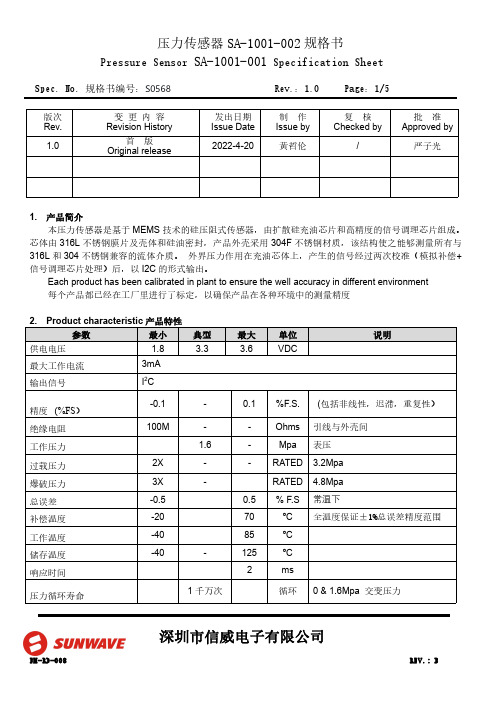
Spec.No.规格书编号:S0568Rev.:1.0Page:1/5深圳市信威电子有限公司版次Rev.变更内容Revision History发出日期Issue Date 制作Issue by 复核Checked by批准Approved by 1.0首版Original release2022-4-20黄哲伦/严子光1.产品简介本压力传感器是基于MEMS 技术的硅压阻式传感器,由扩散硅充油芯片和高精度的信号调理芯片组成。
芯体由316L 不锈钢膜片及壳体和硅油密封,产品外壳采用304F 不锈钢材质,该结构使之能够测量所有与316L 和304不锈钢兼容的流体介质。
外界压力作用在充油芯体上,产生的信号经过两次校准(模拟补偿+信号调理芯片处理)后,以I2C 的形式输出。
Each product has been calibrated in plant to ensure the well accuracy in different environment 每个产品都已经在工厂里进行了标定,以确保产品在各种环境中的测量精度Spec.No.规格书编号:S0568Rev.:1.0Page:2/5深圳市信威电子有限公司3.输出接口及管脚定义注:1.产品的内部电路已经在I2C 总线上放置了4.7K 的上拉电阻2.所有管脚与产品的金属外壳之间是绝缘的4.产品外形结构(单位:mm )5.功能描述5.1.工作模式传感器的默认工作模式为:产品上电后,进入到休眠状态,仅在接收到相应的I2C 命令后才会启动一次压力和温度的测量动作,之后再次自动进入休眠状态,以节省功耗。
5.2.上电启动及休眠唤醒当电源电压小于0.2V 时,传感器处于复位状态,在电源电压以最低10V/ms 的上升速率经过1ms 的延迟后,I2C 接口处于正常状态,可以接受主机命令,在经过2.5ms 的延迟后,传感器可以进行正常的压力和温度测量。
当传感器处于休眠状态时,在接收到主机命令后的0.5ms 时间内从休眠状态进入到工作模式,详细请参Spec.No.规格书编号:S0568Rev.:1.0Page:3/5深圳市信威电子有限公司照上电时序图6.I2C 接口6.1.I2C 接口电气特性在产品内部,I2C 总线的时钟信号线和数据线已经具有4.7k 的上拉电阻6.2.I2C 通讯速率本传感器的I2C 接口可工作于标准模式(100Kbit/s )、快速模式(400Kbit/s)、和高速模式(3.4Mbit/s)。
OMEGA PX540 Series 压力传感器操作手册说明书

PX540 Series Pressure Transducers Operator’s Manual: M1137/0698General DescriptionThe OMEGA®PX540 Pressure Transducer consists of a pressure connection section with welded stainless steel diaphragm and a case for housing the electronic equipment and the electrical connection. The piezoresistive pres-sure sensor is installed behind the diaphragm, with the intervening space filled with silicone oil as pressure trans-mission liquid.The pressure sensor’s signal is converted by an amplifier to a signal of 4 to 20 mA. The pressure connection DIN 3852 is used as a seal behind threads by means of the added NBR O-ring. (No flush-mounted seal). Characteristics of this transducer include:• 4 to 20 mA current output which is ideal for long distance signal transmitting and industrial environments.• High accuracy and repeatability.• Corrosion resistant, and• Rugged NEMA=12 dust-tight/drip-tight enclosure.How To Adjust Zero and SpanNOTE:Unit has been factory calibrated. No adjustment isrequired upon delivery from OMEGA Engineering.Zero adjustment must be performed at no pressureand the output reading must be 4 mA.Span adjustment must be performed at full scale pres-sure and the output reading must be 20 mA.If you do not get either of these readings at therequired no pressure or full scale pressure, go through the following procedure to get to the screws. Remove the connector from the body of the transmit-ter as described in steps 1 and 2 in the Wiring Section. Adjust the zero screw so the output reading is 4 mA at no pressure. At full scale pressure, the output must be 20 mA; if it is not, adjust the span screw.The Zero screw is marked with a white dot. The span screw is marked with a red dot. Refer to Figure 1.Figure 1. Location of AdjustmentScrewsWiringTo access the screw terminals and wire the transducer, refer to Figure 2, and the following procedure.1.Locate the screw at the top of the transducer and unscrew.2.Separate connector from the rest of the transducer body. Remove the screw and rubber gasket from the connec-tor and set aside.ing a small blade screwdriver, insert it in the corner slot and pry off square cover (and terminals).4.Insert cable into hole (not screw hole) and feed through into square part of assembly. Wire terminals in terminalblock using wiring diagram (refer to Figure 3).5.Replace terminal block and snap in place.6.Put rubber gasket on unit.7.Connect larger part of transducer to wired unit observing positions of blades.8.Insert screw in screw hole and tighten two parts to each other.Figure 2. Pressure TransducerFigure 3. Wiring DiagramSpecificationsExcitation:10 to 30 VDCOutput: 4 to 20 mA two wireInsulation Resistance:500 V ACMaximum Loop Impedance:(Supply V oltage -10) x 50 (refer to Figure 4)PerformanceAccuracy:0.3% F.S. Typ (0.5% max)Hysteresis and Repeatability:0.1% F.S.Compensated T emperature Range:32˚ to 122˚ F (0˚ to 50˚ C)Operating T emperature Range:-4˚ to 175˚ F (-20˚ to 80˚ C)Thermal Zero Effect:0.03% F.S./˚ CThermal Sensitivity Effect:0.03% F.S>/˚ CMaximum Pressure:150% Full ScaleConstructionBody Material:Stainless steelWetted Parts:ANSI 316L Stainless steelFill Fluid:Silicone oilProcess Connection:1/2 NPT maleElectrical Connection:DIN connector with screw terminals Response Time: 2 msWeight:0.35 lb.Dimensions:Refer to Figure 5.Benelux:Postbus 8034, 1180 LA Amstelveen, The NetherlandsTel: (31) 20 6418405 FAX: (31) 20 6434643Toll Free in Benelux: 06 0993344e-mail:************Czech Republic:ul. Rude armady 1868, 733 01 Karvina-Hranice,Czech RepublicTel: 420 (69) 6311899FAX: 420 (69) 6311114e-mail:***************France:9, rue Denis Papin, 78190 TrappesTel: (33) 130-621-400 FAX: (33) 130-699-120Toll Free in France: 0800-4-06342e-mail:****************Servicing Europe:USA and Canada:Sales Service: 1-800-826-6342/ 1-800-TC-OMEGA Customer Service: 1-800-622-2378/ 1-800-622-BEST Engineering Service: 1-800-872-9436/1-800-USA-WHEN TELEX: 996404EASYLINK: 62968934 CABLE: OMEGA USA: ISO 9001 Certified One Omega Drive, Box 4047Stamford, CT 06907-0047Tel: (203) 359-1660FAX: (203) 359-7700e-mail:**************Servicing North America:For immediate technical or application assistance:Mexico and Latin America:Tel: (95) 800-TC-OMEGA FAX: (95) 203-359-7807En Espan~ol: (203) 359-7803 e-mail:*****************Germany/Austria:Daimlerstrasse 26, D-75392 Deckenpfronn, GermanyTel: 49 (07056) 3017 FAX: 49 (07056) 8540Toll Free in Germany: 0130 11 21 66e-mail:*****************United Kingdom: ISO 9002 Certified•One Omega Drive, Riverbend Tech Centre, Northbank, Irlam,Manchester, M44 5BD, EnglandTel: 44 (161) 777-6611 FAX: 44 (161) 777-6622Toll Free in England: 0800-488-488e-mail:************Canada:976 BergarLaval (Quebec) H7L 5A1Tel: (514) 856-6928FAX: (514) 856-6886e-mail:****************RETURN REQUESTS / INQUIRIESDirect all warranty and repair requests/inquiries to the OMEGA ENGINEERING Customer Service Department. BEFORE RET URNING ANY PRODUCT (S) T O OMEGA, PURCHASER MUST OBTAIN AN AUT HORIZED RET URN (AR) NUMBER FROM OMEGA’S CUST OMER SERVICE DEPART MENT (IN ORDER TO AVOID PROCESSING DELAYS). The assigned AR number should then be marked on the outside of the return package and on any correspondence.FOR WARRANTY RETURNS, please have thefollowing information available BEFORE con-tacting OMEGA:1.P .O. number under which the product wasPURCHASED,2.Model and serial number of the product under warranty, and 3.Repair instructions and/or specific problems relative to the product.FOR NON-WARRANTY REPAIRS OR CALIBRA-TION,consult OMEGA for current repair/calibra-tion charges. Have the following information avail-able BEFORE contacting OMEGA:1.P .O. number to cover the COST of the repair/calibration,2.Model and serial number of product, and3.Repair instructions and/or specificproblems relative to the product.OMEGA’s policy is to make running changes, not model changes, whenever an improvement is possible. This affords our customers the latest in technology and engineering.OMEGA is a registered trademark of OMEGA ENGINEERING, INC.© Copyright 1995 OMEGA ENGINEERING, INC. All rights reserved. This documentation may not be copied, pho-tocopied, reproduced, translated, or reduced to any electronic medium or machine-readable form, in whole or in part, without prior written consent of OMEGA ENGINEERING, INC.WARRANTYOMEGA warrants this unit to be free of defects in materials and workmanship and to give satisfacto-ry service for a period of 13 months from date of purchase. OMEGA Warranty adds an additional one (1) month grace period to the normal one (1) year product warranty to cover handling and ship-ping time. This ensures that OMEGA’s customers receive maximum coverage on each product. If the unit should malfunction, it must be returned to the factory for evaluation. OMEGA’s Customer Service Department will issue an Authorized Return (AR) number immediately upon phone or written request.Upon examination by OMEGA, if the unit is found to be defective it will be repaired or replaced at no charge. However, this WARRANTY is VOID if the unit shows evidence of having been tampered with or shows evidence of being damaged as a result of excessive corrosion; or current, heat, moisture or vibration; improper specification; misapplication; misuse or other operating conditions outside of OMEGA’s control. Components which wear or which are damaged by misuse are not warranted. These include contact points, fuses, and triacs.OMEGA is glad to offer suggestions on the use of its various products. Nevertheless,OMEGA only warrants that the parts manufactured by it will be as specified and free of defects.OMEGA MAKES NO OTHER WARRANTIES OR REPRESENTATIONS OF ANY KIND WHATSO-EVER, EXPRESSED OR IMPLIED, EXCEPT THAT OF TITLE AND ALL IMPLIED WARRANTIES INCLUDING ANY WARRANTY OF MERCHANTABILITY AND FITNESS FOR A PARTICULAR PURPOSE ARE HEREBY DISCLAIMED.LIMITATION OF LIABILITY: The remedies of purchaser set forth herein are exclusive and the total liability of OMEGA with respect to this order, whether based on contract, warranty,negligence, indemnification, strict liability or otherwise, shall not exceed the purchase price of the component upon which liability is based. In no event shall OMEGA be liable for consequential, incidental or special damages.Every precaution for accuracy has been taken in the preparation of this manual; however, OMEGA ENGINEERING, INC. neither assumes responsibility for any omissions or errors that may appear nor assumes liability for any damages that result from the use of the products in accordance with the infor-mation contained in the manual.SPECIAL CONDITION: Should this equipment be used in or with any nuclear installation or activity,purchaser will indemnify OMEGA and hold OMEGA harmless from any liability or damage whatsoev-er arising out of the use of the equipment in such a manner.Figure 5. Dimensional DiagramOver 100,000 Products AvailableOnline at TEMPERATUREⅪߜThermocouple, RTD & Thermistor Probes, Connectors, Panels & Assemblies ⅪߜCalibrators & Ice Point ReferencesⅪߜRecorders, Controllers & Process MonitorsⅪߜInfrared PyrometersPRESSURE, STRAIN AND FORCEⅪߜTransducers & Strain GagesⅪߜDisplacement TransducersⅪߜInstrumentation & AccessoriesFLOW/LEVELⅪߜRotameters, Gas Mass Flowmeters & Flow ComputersⅪߜAir Velocity IndicatorsⅪߜTurbine/Paddlewheel SystemspH/CONDUCTIVITYⅪߜpH Electrodes, Testers & AccessoriesⅪߜBenchtop/Laboratory MetersⅪߜControllers, Calibrators, Simulators & PumpsⅪߜIndustrial pH & Conductivity EquipmentDATA ACQUISITIONⅪߜData Acquisition & Engineering SoftwareⅪߜCommunications-Based Acquisition SystemsⅪߜPlug-in Cards for Apple, IBM & CompatiblesⅪߜRecorders, Printers & PlottersHEATERSⅪߜHeating Cable, Cartridge & Strip HeatersⅪߜImmersion & Band HeatersⅪߜFlexible HeatersENVIRONMENTALMONITORING AND CONTROLⅪߜMetering & Control InstrumentationⅪߜPumps & TubingⅪߜAir, Soil & Water MonitorsⅪߜIndustrial Water & Wastewater TreatmentONE OMEGA DRIVE, STAMFORD, CT 06907 USATEL:1-888-TC-OMEGA(1-888-826-6342)。
系列压力传感器操作手册

1. 设定参考输出状态:在量测模式下按
键超过四秒,屏幕出现
后放开,进入进阶设定模式。按
色的参考项目(详见进阶设定模式方块图)。按
键选择所要的参考项目。
键四下可看见设定颜
2. 颜色切换:在量测模式下按
键超过二秒,切入简易设定模式。按
键四下可看见设定显示颜色切换功能(详见简易设定模式
方块图)。按
键选择所要的显示颜色
注:「输出一 and 输出二」是当输出一以及输出二皆为 ON 时,才为 ON,否则皆为 OFF;「输出一 or 输出二」是当输出一以及输出二
皆为 OFF 时,才为 OFF,否则皆为 ON。
Code 代码
DPB 提供显示代码,供用户对照设定。在量测模式下按
键超过四秒,屏幕出现
下可看见显示代码(详见进阶设定模式方块图) 代码相关意义如下表:
键找到
,
设定所需的单位。
2. 输出状态:DPB 可设定两种输出状态,N.O.(常开)和 N.C.(常闭)。用户可在简易设定模式下,按 出一、二的输出状态。
键找到
,设定输
3. 反应时间设定:当压力达到输出状态时的反应时间。如设定为 50 代表当压力达到输出状态时必须维持 50ms,输出才会动作。用户可
6. 设定功能键 7. 向下调整键 8. 电源和输出信号端子 9. 压力输入气孔
DPB 1 2 量测压力范围 3 输出型式 4 压力气孔型式
台达 DPB 系列压力传感器 01: -100kPa ~ 100kPa, 10: -100kPa ~ 1,000kPa N: NPN output;P: PNP output P:外孔 PT 1/8、内孔 M5;N:外孔 NPT 1/8、内孔 M5;G:外孔 G 1/8、内孔 M5
《传感器与检测技术》基于多传感器的老年人跌倒检测报警系统设计设计
《传感器与检测技术》跌倒检测器摘要:随着人口老龄化进程的加快,老年人监护和医疗问题正成为一个重大的社会问题。
老年人意外受伤害的首要原因就是跌倒,因此,研究助老产品——跌倒检测器,将大大改善老年人的健康品质,对构建和谐社会的意义重大。
本课题设计了一种基于多传感器的老年人跌倒检测报警系统,依托嵌入式单片机STM32F101R8T6,利用普通的加速度传感器,对人体的空间三个方向的加速度值进行采集,倾角传感器采集人体的前后和左右倾角值,并且脚底压力传感器感知脚部的压力值。
关键词:跌倒检测,多传感器,倾角传感器1 前言1.1 课题背景21世纪的来临,使全世界范围内人口老年化的进程加快,在这种全球趋势的情形下,中国也不例外,随着我国人口老年化进程的加剧,社会对这一群体的健康保障将承担越来越艰巨的责任。
年龄的增长,身体解剖组织结构和生理代谢发生变化,由于自身疾病或者外界的影响,老年人常会发生意外跌倒,有时候甚至是健康的老年人也会发生,据国外研究机构统计,约有的超过65岁的老人平均每年发生一次跌倒,且随着年纪的增加,概率也增加,而本身身体有病痛或者伤害的老人,就更容易发生意外的跌倒。
而跌倒次数巨大的背后,是由跌倒带来的辅助治疗所需消耗的高昂费用,以及照顾跌倒人群消耗的巨额社会资源,有研究表明,社会支付的医疗费用超过50万亿元,而付出的代价则为160-800万亿元人民币。
然而,跌倒造成的伤害不仅体现在身体的即时受伤,还体现在未得到及时的帮助而造成的所有后续恶劣影响。
所以,针对跌倒问题,除了做好事先防范工作之外,如安全教育等,还应该在发生跌倒时,最快的将受伤人员送往医院进行救治,所以发明一个能够实时监测到跌倒并通知医护人员救治的产品很重要。
1.2 国内外研究现状目前对老年人跌倒检测技术相关研究主要的研究成果是利用加速度传感器检测装置,监测在跌倒事件发生时人体各方向加速度值,利用阈值检测或者模式识别的方法,对老年人的身体姿势状态进行实时检测,算法判断到处于跌倒状态后,再利用远程无线报警系统进行报警,通知护理人员进行救治,实现老年人的远程监护。
压力传感器操作指南说明书
压力传感器操作指南说明书操作指南说明书1. 产品概述本操作指南说明书旨在向用户介绍压力传感器的正确操作方法。
压力传感器是一种用于测量物体压力或压力变化的设备,广泛应用于工业领域中的自动化控制系统中。
本说明书将详细介绍压力传感器的各个部件、规格参数以及正确的使用方法。
2. 产品组成压力传感器主要由以下部件组成:- 压力感应器头:用于感知物体的压力,并将其转换为电信号。
- 电路板:将压力感应器头的信号转换为数字信号,通过接口与控制系统进行通信。
- 接口:用于与外部设备连接,传输数字信号。
3. 使用前准备在开始使用压力传感器之前,请确保以下步骤已完成:- 检查传感器的外观是否完好,如有损坏请勿使用。
- 查看产品标识,确认传感器是否适用于您的应用场景。
- 连接传感器到合适的电源,并确保电源电压符合规定。
4. 使用步骤4.1 连接传感器将传感器的接口与控制系统的接口连接,确保连接稳固且无松动。
4.2 设定工作参数根据实际需求,通过控制系统设置传感器的工作参数,如测量范围、刷新频率等。
4.3 校准传感器首次使用传感器或者在长时间使用后,应进行校准操作,以确保精准测量。
具体校准方法请参考附带的校准指南。
4.4 启动传感器通电后,传感器会自动进行初始化,并开始测量工作。
在使用过程中,传感器会持续监测压力变化,并将测量结果通过控制系统进行处理和显示。
4.5 关闭传感器在不使用传感器时,应及时关闭电源,避免长时间不必要的功耗。
5. 注意事项- 请勿在高温、潮湿、腐蚀性环境中使用传感器,以免影响性能和寿命。
- 请勿将压力传感器投掷、撞击或受到过大的力量挤压,以免损坏设备。
- 若传感器长时间不使用,请妥善保管,并放置在干燥、清洁的环境中。
6. 故障排除一旦发现传感器工作异常或显示数值不准确,应立即停止使用,并进行以下检查:- 检查设备连接是否松动或损坏。
- 检查控制系统设置是否正确。
- 尝试重新校准传感器。
若问题仍未解决,请联系售后服务中心或厂家进行进一步的维修和处理。
第3章-相位调制型光纤传感器
MZ干涉仪的应用例-线性调频外差型干涉仪
固定光程差(~10cm-由光 源线L 宽L决定L) n L D
检测:锁相、比较和计数
L n
D
隔离器 耦合器
耦合器
解决:
条纹高细DBF分困难,导致精度不高折射率变化区 测量灵驱敏动度和精度随光程差改变;
易受外界环境影响等
用声光调制器的外差式干涉结构复杂、体积大、调制频率范围 小的矛盾
等无关
问题:低相干度光源的获得、零级干涉条纹的检 测
应用
* 相位信号解调技术
相位调制型
干涉仪的信号解调 光纤锁相环方案 PGC(phase generator carrier)方案
干涉仪的解调方案
主动零差法 被动零差法 普通外差法 合成外差法 伪外差法
零差法 外差法
相位调制型
❖ 补充条件
❖ 利用原子发出的同一波列 ❖ 光程差要小于波列长度
相位调制型
光纤中的相位调制
应力/应变调制 温度调制 可以转化的调制
相位调制型
5.3.1 相位调制机理
相位调制型
应力应变效应
通过长L的光纤,出射光 波的相位延迟:
光波在外界因素影响下 的相位变化:
L 2 L
L L L L L n L a
干涉测量原理
相位调制型
双光束干涉:
多光束干涉
A2 A12 A22 2A1A2cos()
I I0
1
(1
4R R)2
sin2
2
结论
R:反射率;φ:相邻光束的相位差
discriminability(sensitivity) R
5.3.2 光纤干涉仪1-2
相位调制型
DM-SFSR402电阻式压力传感器使用说明书
电阻式压力传感器用户使用说明书V1.0深圳市中科鸥鹏智能科技有限公司2010年11月目录1.简介 (3)2.技术参数 (3)3.注意事项 (4)4.安装方法及软件 (5)1.简介FSR402是著名Interlink Electronics 公司生产的一款重量轻,体积小,感测精度高,超薄型电阻式压力传感器。
这款压力传感器是将施加在FSR传感器薄膜区域的压力转换成电阻值的变化,从而获得压力信息。
压力越大,电阻越低。
其允许用在压力100g-10kg的场合。
可用于机械夹持器末端感测有无夹持物品,仿生机器人足下地面感测,哺乳类动物咬力测试生物实验,应用范围及其广泛。
但是由于压力检测不是非常精确,因此不建议使用需要精确检测压力的场合。
2.技术参数●工作电压:5VDC@165mA●传感器感应面积:直径12.7mm●传感器类型:被动式可变电阻●压力感应范围:100g ~ 10 kg●使用寿命:>100万次挤压图1压力感应电阻是弯曲压力传感器的一种,简称FSR,FSR是一种随着有效表面上压力增大而输出阻值减小的高分子薄膜,FSR并不是测压元件或形变测量仪,尽管他们有着相似的性能。
而且这类压力感测电阻不适用于精密测量,但是FSR却是一款灵敏度较高的传感器。
图2图3这是它的性能曲线3.注意事项FSR的厚度为0.2mm—1.25mm,这款传感器的厚度为0.3mm。
压力敏感范围是从100g 到10kg.。
声压灵敏度是从0.1kg/cm²到10 kg/cm²。
在安装时有几个注意事项:●要尽量选择稳固,光滑且平坦的安装表面;●当你的安装表面是曲面时,你安装FSR时势必会弯曲它,这样一来FSR就会受力,就会一定程度上影响到FSR的精确度,所以要注意尽量不要将FSR的有效表面安装在曲面上(注:是圆形有效表面不可弯曲,而长尾部可以弯曲);●要保持接触表面的清洁;●受力不要超过它的额定值;●尽量不要将它焊接到万用板或没有属于它的特定封装的电路板上,以免尾部会受热变形;●若用导线将其接入电路,注意最好要用热缩管将尾部两部分隔开。
- 1、下载文档前请自行甄别文档内容的完整性,平台不提供额外的编辑、内容补充、找答案等附加服务。
- 2、"仅部分预览"的文档,不可在线预览部分如存在完整性等问题,可反馈申请退款(可完整预览的文档不适用该条件!)。
- 3、如文档侵犯您的权益,请联系客服反馈,我们会尽快为您处理(人工客服工作时间:9:00-18:30)。
fsr压力传感器技术手册
FSR 压力传感器(Force Sensing Resistor,力敏电阻)是一种具有出色性能和广泛应用的压力传感器。
它通过测量电阻值的变化来感应外界的压力变化,从而实现对压力的测量。
以下是一份FSR 压力传感器技术手册的大致内容:
一、FSR 压力传感器简介
1. 工作原理:FSR 压力传感器是一种基于压阻效应的传感器,当受到压力作用时,其电阻值会发生明显变化。
通过测量这种变化,可以获得压力的大小。
2. 特点:FSR 压力传感器具有高灵敏度、高线性度、良好的重复性和稳定性,适用于各种压力测量场景。
二、FSR 压力传感器的分类
1. 按结构分类:FSR 压力传感器可分为薄膜型、硅膜型、陶瓷型等不同类型。
2. 按输出信号分类:FSR 压力传感器可分为模拟输出型和数字输出型。
三、FSR 压力传感器的主要性能指标
1. 灵敏度:FSR 压力传感器的灵敏度指受压力变化引起的电阻变化率。
灵敏度越高,压力传感器的测量范围越大。
2. 线性度:FSR 压力传感器的线性度指传感器输出与输入压力之间的线性关系。
线性度越好,传感器的测量精度越高。
3. 精度:FSR 压力传感器的精度指传感器测量结果与真实值之间的偏差。
精度越高,传感器的可靠性越好。
4. 响应时间:FSR 压力传感器的响应时间指传感器输出信号达到90% 峰值的时间。
响应时间越短,传感器对压力变化的反应速度越快。
5. 工作温度范围:FSR 压力传感器的工作温度范围指传感器在正常工作条件下能稳定运行的温度范围。
工作温度范围越宽,传感器的适应性越强。
四、FSR 压力传感器的应用领域
1. 电子设备:FSR 压力传感器广泛应用于电子设备中,如智能手机、平板电脑、笔记本等,实现对触摸屏、按键等部件的压力检测。
2. 汽车电子:FSR 压力传感器在汽车电子领域中的应用日益广泛,如汽车安全气囊、座椅调节器、车窗升降等系统。
3. 工业自动化:FSR 压力传感器在工业自动化领域中具有广泛应用,如压力控制系统、机器人抓取装置等。
4. 医疗设备:FSR 压力传感器在医疗设备中具有重要应用,如血压计、心电图机等。
五、FSR 压力传感器的选型及使用注意事项
1. 选型:根据应用场景和性能要求,选择合适的FSR 压力传感器类型和规格。
2. 使用注意事项:
(1)避免压力传感器受潮、浸水、暴露在高温或低温环境下;
(2)确保压力传感器的引线牢固可靠,避免损坏;
(3)根据实际需求选择合适的信号处理电路,以实现精确测量;
(4)定期检查压力传感器的性能,确保其正常工作。
本技术手册仅为FSR 压力传感器的简要介绍。
在实际应用中,请根据具体需求选择合适的传感器型号,并确保正确使用和妥善维护。
如有疑问,请随时与供应商或技术专家联系。