gambit连接头网格划分
Gambit网格划分1
1.基本几何结构的创建和网格化本章介绍了GAMBIT中一个简单几何体的创建和网格的生成。
在本章中将学习到:z启动GAMBITz使用Operation工具箱z创建一个方体和一个椭圆柱体z整合两个几何体z模型显示的操作z网格化几何体z检查网格的品质z保存任务和退出GAMBIT1.1 前提在学习本章之前,认为用户还没有GAMBIT的使用经验,不过,已经学习过前一章“本指南的使用”,并且熟悉GAMBIT界面以及本指南中所使用的规约。
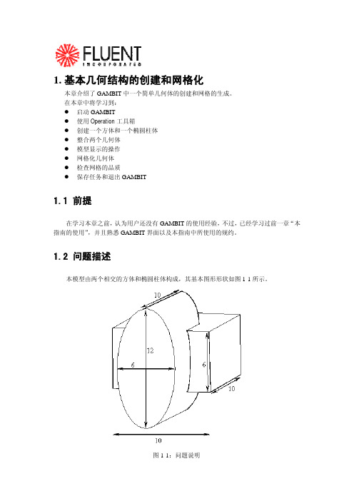
1.2 问题描述本模型由两个相交的方体和椭圆柱体构成,其基本图形形状如图1-1所示。
图1-1:问题说明1.3策略本章介绍使用GAMBIT生成网格的基本操作,特别地,将介绍:z如何使用“top-down”固体建模方法来方便地创建几何体z如何自动生成六面体网格“top-down”方法的意思是用户可以通过生成几何体(如方体、柱体等)来创建几何结构,然后,对它们进行布尔操作(如整合、剪除等),以这种方式,用户不用首先去创建作为基础的点、边和面,就可以快速创建出复杂的几何形体。
一旦创建出一个有效的几何模型,网格就可以直接并且自动地(很多情况下)生成。
在本例子中,将采用Cooper网格化算法来自动生成非结构化的六面体网格。
更复杂的几何结构在生成网格之前可能还需要进行手工分解,这将在后面进行介绍。
本章的学习步骤如下:z创建两个几何体(一个方体和一个椭圆柱体)z整合两个几何体z自动生成网格z检查网格的品质为了使本章的介绍尽量简短,一些必要的步骤被省略了:z调节几何体单边上节点的分布z设置连续介质类型(例如,标识哪些网格区是流体,哪些网格区是固体)和边界类型这些方面的详细内容,也包括其他方面,在随后的章节将涉及到。
1.4步骤输入gambit -id basgeom启动GAMBIT。
这就打开了GAMBIT的图形用户界面(GUI)(图1-2)。
GAMBIT把设定的名称(本例子中为basgeom)作为她将创建的所有文件的词头,如:basgeom.jou。
第三章 GAMBIT网格划分基础-1

3.1.4 生成体网格 对于三维流动问题,必须生成三维实体网格。Gambit 提 供五种体网格的生成方法。 1、映射网格
对于六面体结构,可以使用映射网格方法直接生成六面体网格。
对于较为复杂的几何形体,必须在划分网格前将其分割为若干个 六面体结构。
2、子映射网格
Gambit 软件的子映射网格划分技术同样适用于体网格。也就是
视图和视图控制面板
Gambit 中可显示四个视图,以便于建立三维
模型。同时我们也可以只显示一个视图。视图 的坐标轴由视图控制面板来决定。图3.2.2 显 示的是视图控制面板。 视图控制面板中的命令可分为两个部分,上面 的一排四个图标表示的是四个视图,当激活视 图图标时,视图控制面板中下方十个命令才会 作用于该视图。
3、自由网格
对于拓扑形状较为复杂的面,可以生成自由网格,用户可以选择
合适的网格类型(三角形或四边)。
3.1.3 边界层网格 CFD 计算对计算网格有特殊的要求,一是考虑到近壁粘 性效应采用较密的贴体网格,二是网格的疏密程度与流场 参数的变化梯度大体一致。 对于面网格,可以设置平行于给定边的边界层网格,可以 指定第二层与第一层的间距比,及总的层数。 对于体网格,也可以设置垂直于壁面方向的边界层,从而 可以划分出高质量的贴体网格。而其它通用的CAE 前处 理器主要是根据结构强度分析的需要而设计的,在结构分 析中不存在边界层问题,因而采用这种工具生成的网格难 以满足CFD 计算要求,而Gambit 软件解决了这个特殊要 求。
第三章 GAMBIT网格划分基础
曹双华 主讲 07/04
结构网格和非结构网格的区别
结构网格就是在一定区域内的网格点可以用统一 的编号,比如三维的网格点可以用连续i,j,k唯 一标志并且可以表达相互之间的位置关系,比较 节约存储空间,利于编程计算,但对复杂流场的 适应性较差。 非结构网格一般是每个单独的网格单元都有独立 的编号,并且最后要附加一个全场的总编号来确 定每个单独网格之间的关系,占用的存储空间较 大,编程比较麻烦,但是对复杂流场的适应性较 好。
Gambit网格划分

1.基本几何结构的创建和网格化本章介绍了GAMBIT中一个简单几何体的创建和网格的生成。
在本章中将学习到:z启动GAMBITz使用Operation工具箱z创建一个方体和一个椭圆柱体z整合两个几何体z模型显示的操作z网格化几何体z检查网格的品质z保存任务和退出GAMBIT1.1 前提在学习本章之前,认为用户还没有GAMBIT的使用经验,不过,已经学习过前一章“本指南的使用”,并且熟悉GAMBIT界面以及本指南中所使用的规约。
1.2 问题描述本模型由两个相交的方体和椭圆柱体构成,其基本图形形状如图1-1所示。
图1-1:问题说明1.3策略本章介绍使用GAMBIT生成网格的基本操作,特别地,将介绍:z如何使用“top-down”固体建模方法来方便地创建几何体z如何自动生成六面体网格“top-down”方法的意思是用户可以通过生成几何体(如方体、柱体等)来创建几何结构,然后,对它们进行布尔操作(如整合、剪除等),以这种方式,用户不用首先去创建作为基础的点、边和面,就可以快速创建出复杂的几何形体。
一旦创建出一个有效的几何模型,网格就可以直接并且自动地(很多情况下)生成。
在本例子中,将采用Cooper网格化算法来自动生成非结构化的六面体网格。
更复杂的几何结构在生成网格之前可能还需要进行手工分解,这将在后面进行介绍。
本章的学习步骤如下:z创建两个几何体(一个方体和一个椭圆柱体)z整合两个几何体z自动生成网格z检查网格的品质为了使本章的介绍尽量简短,一些必要的步骤被省略了:z调节几何体单边上节点的分布z设置连续介质类型(例如,标识哪些网格区是流体,哪些网格区是固体)和边界类型这些方面的详细内容,也包括其他方面,在随后的章节将涉及到。
1.4步骤输入gambit -id basgeom启动GAMBIT。
这就打开了GAMBIT的图形用户界面(GUI)(图1-2)。
GAMBIT把设定的名称(本例子中为basgeom)作为她将创建的所有文件的词头,如:basgeom.jou。
第二章 Gambit划分网格
1)应用分级设定的边
2)分级方案
3)网格节点步长(间隔数目) 4)边网格划分选项
线网格划分
2)分级方案 Gambit 提供了以下类型的边网格划分分级方案:
• • • • • •
•
Successive Ratio First Length Last Length First Last Ratio Last First Ratio Exponent Bi-exponent Bell Shaped
非对称格式,产生的分级 形式不需要关于边的中心对称
对称格式,限制关于边 中心对称的分级类型
•
线网格划分
• 狭长型网格长宽比不要超过5; • 燃烧反应的区域网格尽量细化。
3、面网格划分
进行一个面网格划分,用户必须 设定以下参数:
1)要网格划分的面
2)网格划分的形式 3)网格节点的间距 4)面网格划分选项
体网格光顺化
• Smooth Volume Meshes 在一个或多个体积上光顺化网格节点。 1、选择要光顺化的体积; 2、光顺化方案 L-W Lapiacian:使每个节点 周围单元平均边长; Equipotential:使节点周围单元体积相等。
体网格划分技巧
• 首先画线网格和部分面网格; • 尽量采用五面体和六面体网格,以控制网 格数量; • 复杂结构考虑分块画网格,避免把所有几 何组合成一个整体;
平整面网格
Smooth Faces Meshes命令 将调整一个或者多个面网格节点的位置 用户需设定以下参数: 1)要平整的网格面 2)平整方式 L-W Laplalian :在每个节点周围使用单元的平均变长(趋向平 均单元 边长)
Centroid Area :平衡相邻单元的面积
gambit网格
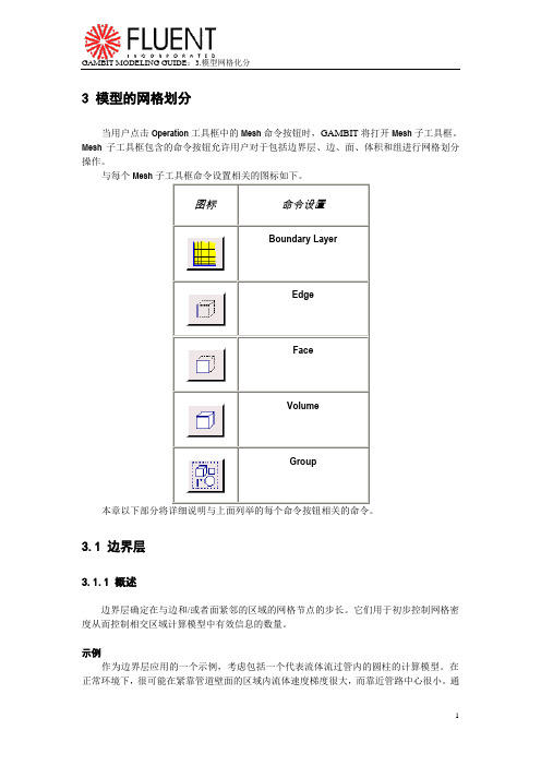
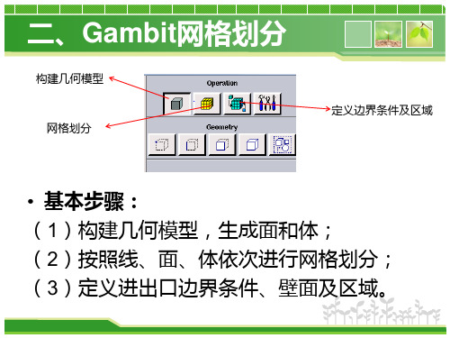
3 模型的网格划分当用户点击Operation工具框中的Mesh命令按钮时,GAMBIT将打开Mesh子工具框。
Mesh子工具框包含的命令按钮允许用户对于包括边界层、边、面、体积和组进行网格划分操作。
与每个Mesh子工具框命令设置相关的图标如下。
本章以下部分将详细说明与上面列举的每个命令按钮相关的命令。
3.1 边界层3.1.1 概述边界层确定在与边和/或者面紧邻的区域的网格节点的步长。
它们用于初步控制网格密度从而控制相交区域计算模型中有效信息的数量。
示例作为边界层应用的一个示例,考虑包括一个代表流体流过管内的圆柱的计算模型。
在正常环境下,很可能在紧靠管道壁面的区域内流体速度梯度很大,而靠近管路中心很小。
通过对壁面加入一个边界层,用户可以增大靠近壁面区域的网格密度并减小靠近圆柱中心的网格密度——从而获得表征两个区域的足够的信息而不过分的增大模型中网格节点的总数。
一般参数要确定一个边界层,用户必须设定以下信息:∙边界层附着的边或者面∙确定边界层方向的面或者体积∙第一列网格单元的高度∙确定接下来每一列单元高度的扩大因子∙确定边界层厚度的总列数用户还可以设定生成过渡边界层——也就是说,边界层的网格节点类型随着每个后续层而变化。
如果用户设定了这样一个边界层,用户必须同时设定以下信息:∙边界层过渡类型∙过度的列数3.1.2 边界层命令生成边界层Create Boundary Layer命令允许用户在一条边或者一个面附近定义网格节点步长。
要生成一个边界层,用户必须设定以下参数:∙定义∙过渡特性∙附着实体和方向设定边界层定义要定一边界层,用户必须设定两类特征:∙尺寸∙内部连续性∙角形状尺寸特征包括诸如边界层列数以及第一列高度等因数。
内部连续性特征确定边界层重叠在相邻边界层印记上的印记行为。
角形状特征确定网格在连接边界层与附着边的Corner 或者Reversal点周围区域的网格形状。
设定尺寸特征要设定边界层的尺寸特征,用户必须设定以下四个参数中的三个:∙第一列高度∙增长因子∙列数∙总高度上面列举的前三个参数定义如下(如图3-1):∙第一列高度(a)设定边界层附着的边或者面与网格节点第一个完整列之间的距离。
第三章:gambit划分网格——(第三节)面网格划分
顶点类型
为了能够用 Quad-Map 方案划分网格,面必须描绘出一个逻辑的矩形(此判据的例外情 况见下面部分的“注一”。)。为了描绘出一个逻辑的矩形,一个面必须包括四个端点类型(END TYPE)的顶点,同时其它所有的面上的顶点必须指定为侧边类型(SIDE TYPE)的顶点。
Quad-Map 网格划分方案(meshing scheme)
当对一个面采用 Quad-Map 网格划分方案,GAMBIT 采用规则的四边形面网格元素对 面进行网格划分,如图 3-22 所示:
图 3-22:Quad-Map 面网格划分方案(scheme)-网格例子
本文由 wyxpuma 提供,不足之处欢迎指正
图 3-23 画出了四个平面,其中两个可以采用(Quad)Map 方案划分网格,另两个则 不行。图(a)和(c)是可以的,因为每个平面中都有四个端点类型的顶点(End type vertex), 而其它顶点为侧边类型的顶点(Side type vertex)。图(b)无法用 Map 方法,因为该平面只 包含了三个端点型顶点;图(d)也无法采用 Map 方法,因为该平面上的某个顶点被指定为 反向型(Reversal)顶点。
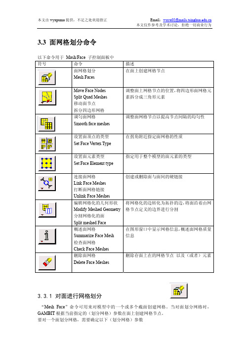
创建或删除面与面间的硬链接
将网格化的边转化为拓扑的边,将面沿着由网 格节点定义的边界进行分割
在图形窗口中显示网格信息,概述面网格质量 信息
删除存面上在的网格节点 以及(或者)元素
3.3.1 对面进行网格划分
“Mesh Face”命令可用来对模型中的一个或多个截面创建网格。当对面划分网格时, GAMBIT 根据当前指定的(划分网格)参数在面上创建网格节点。 要对一个面划分网格,需要确定以下(划分网格)参数
利用Gambit 划分网格
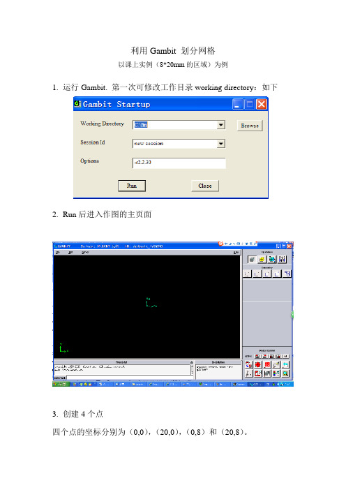
利用Gambit 划分网格以课上实例(8*20mm的区域)为例1.运行Gambit. 第一次可修改工作目录working directory:如下2.Run后进入作图的主页面3.创建4个点四个点的坐标分别为(0,0),(20,0),(0,8)和(20,8)。
只需要在Global栏填入数值4.利用右下角的工具Fit to window按钮可以使所有几何点出现在视图区。
5.创建4条线利用按钮,出现此时按住shift键,用鼠标左键点击一个点,此时该点变为红色(表面已选择),如:,同样方法再选择一个点,然后按Apply 即将这两点连成一条线,如下图最终四个建立4条边线,如下图6.建立一个面(这就是要求解的区域)点击工具栏中的建立面。
按住shift键,用鼠标左键点击一条线,此时该线条变为红色(表面已选择),依次再选择另3条线(此时按住shift键不动)。
然后按Apply即将这4条线组成一个面。
7.进行网格划分选择右上角中的面网格划分选择仅有的一个面face1, 方法是按住shift键,用鼠标左键点击面的任一条线,此时面的四条线改为红色,表示已选择。
将步长值改为0.5。
空间步长越小,网格数越多,计算可能更准确,但是计算时间越长。
然后点击Apply 得到下面的网格8.初步指定边界的类型点击区域命令按钮,再点击下面左侧的指定边界类型按钮。
选定一个边,可打开向上箭头,将列表中选,也可利用前面的方法,按住shift键,用鼠标左键点击一条线,此时该线条变为红色(表面已选择)。
为选定的边输入一个名字,本问题中我选择的四个边的名字分别为left、up、down和right。
4个边的类型均为默认的Wall。
9.指定求解区域为固体材料点击区域命令按钮选择face1,为选定的面输入一个名字,如zone,将区域的类型由Fluid 改为Soild。
10.导出网格由File中的Export,再选择Mesh. 更改默认的文件名,如改为fin.msh点击Export 2-D(X-Y)mesh 按钮,显示为红色。
GAMBIT 网格划分基础

第二篇预处理技术第三章 GAMBIT网格划分基础GAMBIT软件是Fluent 公司提供的前处理器软件,它包含功能较强的几何建模能力和强大的网格划分工具,可以划分出包含边界层等CFD特殊要求的高质量的网格。
GAMBIT 可以生成FLUENT6、FLUENT5.5、FIDAP、POLYFLOW等求解器所需要的网格。
使用Gambit 软件,将可大大缩短用户在CFD应用过程中建立几何模型和流场以及划分网格所需要的时间。
用户可以直接使用Gambit软件建立复杂的实体模型,也可以从主流的CAD/CAE系统中直接读入数据。
Gambit软件高度自动化,可生成包括结构和非结构化的网格,也可以生成多种类型组成的混合网格。
如果你熟练掌握了GAMBIT, 那么在CFD应用中你将如虎添翼。
让我们赶紧进入GAMBIT的学习吧。
3.1 对连续场的离散化处理现阶段对非定常(完全)N-S方程的直接数值求解往往受到计算机运行速度和内存大小的限制尚不现实,而且工程上对瞬时流场也不感兴趣,因此在实际应用中一般是从简化的数学模型出发,并要在简化模型的复杂程度和可处理的几何外形的复杂程度之间作出某种权衡,要求对模型的合适程度和计算的可行性(物理上和几何上)作出判断。
目前计算流体力学完全可以模拟具有复杂几何外形的简单物理问题或者模拟具有简单几何外形的复杂物理问题,而不能完全模拟既具有几何复杂性又具有物理复杂性的问题,对此仍在进一步发展中。
完全N-S方程按时间平均并按从高到低的层次可简化成雷诺平均N-S方程、边界层方程、无粘非线性方程(如Euler方程、位势方程、跨音速小扰动方程)、无粘线性方程(如Lap1ace方程)等。
从数值求解上述控制方程的进程来看,20世纪60年代解决了无粘线性方程的求解,已能用无粘线性方程模拟相当复杂外形的小攻角绕流,并有大量的实用软件;20世纪70年代主要集中于无粘非线性全位势方程和Eu1er方程的求解,已能用于模拟许多复杂外形的亚、跨、超音速绕流;20世纪80年代较集中于求解雷诺平均N-S方程及其它近似的N-S方程,着重解决定常问题,已取得了丰硕的成果,并趋于成熟;20世纪90年代开始了非定常粘性流场模拟的新局面,并且它已逐渐成为计算流体力学的发展主流。
- 1、下载文档前请自行甄别文档内容的完整性,平台不提供额外的编辑、内容补充、找答案等附加服务。
- 2、"仅部分预览"的文档,不可在线预览部分如存在完整性等问题,可反馈申请退款(可完整预览的文档不适用该条件!)。
- 3、如文档侵犯您的权益,请联系客服反馈,我们会尽快为您处理(人工客服工作时间:9:00-18:30)。
INDUSTRIAL DRILL BIT—DIRECT CAD IMPORT© Fluent Inc., Mar-06 12-1 12. INDUSTRIAL DRILL BIT—DIRECT CAD IMPORTThis tutorial employs the industrial drill-bit model described in Tutorial 12 to illustrate the advantages of importing geometry directly from a CAD program rather than importing the geometry by means of an intermediate (STEP) file. The directly imported geometry does not include the very short edges that required elimination in Tutorial 12, however, it does include some small faces that must be merged to facilitate meshing.In this tutorial, you will learn how to:• Import geometry directly from the Pro/ENGINEER CAD program• Use the GAMBIT cleanup tools to identify and eliminate geometry features thatcan adversely affect meshing operationsNOTE (1): The capability of direct geometry import from the Pro/ENGINEER program requires a special GAMBIT license. Without the license, GAMBIT cannot open a data-base that includes directly imported CAD geometry. NOTE (2): You can reproduce the perspectives of the figures in this tutorial by means of window matrix commands available in a journal file named “tg12_figures.jou ,” which is included in the “help/tutfiles ” online help directory. To exactly reproduce the perspective of any figure, you must open the journal file and execute the window matrix command associated with the figure. For example, the following command repro-duces the perspective of the model shown in Figure 12-3.window matrix 1 entries \ 0.8298196196556 0.1376460045576 -0.5407903790474 \ -0.98521900177 -0.3953186273575 0.828989803791 \ -0.3955990076065 -0.0812062472105 0.3938567638397 \ 0.5420601963997 0.742325425148 -3.794617891312 \ -12.156******** 12.11377906799 -4.06431388855 \ 15.50736236572 -22.28459358215 22.2845935821512.1 PrerequisitesPrior to reading and performing the steps outlined in this tutorial, you should familiarize yourself with the steps, principles, and procedures described in Tutorials 1, 2, 3, 4, 8, and 11.Problem Description INDUSTRIAL DRILL BIT—DIRECT CAD IMPORT 12-2 © Fluent Inc., Mar-0612.2 Problem DescriptionFigure 12-1 and Figure 12-2 show the drill-bit configuration to be modeled and meshed in this tutorial. Figure 12-1 shows the full model, including the outer face that circumscribes the internal components. Figure 12-2 shows the internal components, themselves. Themodel shown in these figures is identical to that described in Tutorial 11.Figure 12-1: Industrial drill bit configuration—full modelINDUSTRIAL DRILL BIT—DIRECT CAD IMPORT Problem Description© Fluent Inc., Mar-0612-3Figure 12-2: Industrial drill bit configuration—internal componentsThe goals of this tutorial are:• To directly import the drill-bit geometry from the Pro/ENGINEER CAD program • To use GAMBIT cleanup operations to render the model suitable for meshing• To mesh the model using unstructured, tetrahedral mesh elements the quality ofwhich is controlled by means of size functionsThis tutorial, in conjunction with Tutorial 11, also illustrates the differences between direct CAD geometry import and geometry import by means of STEP data files. Specifically, this tutorial imports the data directly from the Pro/ENGINEER program as a “part” file. Consequently, the imported geometry does not include the very short edges that otherwise complicate meshing (see Tutorial 11).Strategy INDUSTRIAL DRILL BIT—DIRECT CAD IMPORT12.3 StrategyThe general strategy employed in this tutorial is as follows:1)Start the Pro/ENGINEER program.2)Launch GAMBIT from within Pro/ENGINEER.3)Import to GAMBIT a Pro/ENGINEER part file that describes the drill-bitgeometry.4)Use GAMBIT cleanup operations to eliminate a few small faces that wouldotherwise complicate meshing.5)Apply size functions to control mesh quality.6)Mesh the model.The operations involved in items 4–6, above, are nearly identical to those described in Steps 4–6 of Tutorial 11.12-4 © Fluent Inc., Mar-06INDUSTRIAL DRILL BIT—DIRECT CAD IMPORT Procedure12.4 ProcedureStep 1: Start Pro/ENGINEER1.In a terminal window, entergambit -id Drill_Bit_ProE –proe proe_startup_command where proe_startup_command is the system-specific command to start Pro/-ENGINEER.This command starts Pro/ENGINEER and displays the Pro/ENGINEER user interface.!GAMBIT is available only in a 32-bit version; therefore, the Pro/ENGINEER version used for direct CAD import must also be 32-bit.© Fluent Inc., Mar-06 12-5Procedure INDUSTRIAL DRILL BIT—DIRECT CAD IMPORT 12-6 © Fluent Inc., Mar-06Step 2: Start GAMBIT from within Pro/ENGINEER1. Start GAMBIT and make it available as an option on the Pro/ENGINEER main menu.a) Open the Pro/ENGINEER Auxiliary Applications form.Tools → Auxiliary Applications…This command sequence opens the Pro/ENGINEER Auxiliary Applicationsform.i. In the list of available auxiliary applications, select gambit , and click Start .Pro/ENGINEER starts GAMBIT and displays a new option—titled,Gambit —on the Pro/ENGINEER main menu. Pro/ENGINEER alsodisplays the message, “Application ‘gambit’ started successfully,” toindicate the successful launch of the GAMBIT program.ii. Click Close to close the Auxiliary Applications form.INDUSTRIAL DRILL BIT—DIRECT CAD IMPORT Procedure © Fluent Inc., Mar-06 12-7 Step 3: Open the Part File1. Open the Pro/ENGINEER part file.a) Open the Pro/ENGINEER part file that describes the drill bit geometry.File → Open…This command sequence opens the Pro/ENGINEER File Openform.i. In the file list, select drill_bit.prt , and click Open .Pro/ENGINEER opens the part file and displays it in the Pro/ENGINEERGUI graphics window.! You cannot operate on parts or assemblies from within Pro/ENGI-NEER while GAMBIT is running.Procedure INDUSTRIAL DRILL BIT—DIRECT CAD IMPORT Step 4: Display the GAMBIT User Interface1.Display the GAMBIT graphical user interface.a)On the Pro/ENGINEER main menu, start the GAMBIT interface.Gambit → StartPro/ENGINEER replaces its foreground user interface with that of GAMBITand remains operational in the background.It is possible to switch between Pro/ENGINEER and GAMBIT operationwhile GAMBIT is running.•To switch from GAMBIT to Pro/ENGINEER, you must exit GAMBIT by means of the File/Close option on the GAMBIT main menu bar.When you exit GAMBIT in this manner, the GAMBIT window isiconized, and GAMBIT continues to run until you end its executionfrom within Pro/ENGINEER.•To switch from Pro/ENGINEER to GAMBIT, select the Gambit→Start option on the Pro/ENGINEER main menu bar.To ensure that any GAMBIT operations are preserved when switching backand forth between GAMBIT and Pro/ENGINEER, it is advisable to save theGAMBIT database before switching from GAMBIT to Pro/ENGINEERoperation.12-8 © Fluent Inc., Mar-06INDUSTRIAL DRILL BIT—DIRECT CAD IMPORT Procedure Step 5: Select the Solver1.Choose the solver from the main menu bar:Solver → FLUENT 5/6The choice of solver affects the types of options available in the SpecifyBoundary Types form. For some systems, FLUENT 5/6 is the default solver. Thecurrently selected solver is shown at the top of the GAMBIT GUI.© Fluent Inc., Mar-06 12-9Procedure INDUSTRIAL DRILL BIT—DIRECT CAD IMPORT 12-10 © Fluent Inc., Mar-06 Step 6: Import the CAD GeometryIn this step, you will directly import the drill-bit geometry from Pro/ENGINEER . GAMBIT designates the imported geometry as “CAD” geometry, and assigns its components a “c_” prefix—for example, c_face.123.! To import geometry directly from Pro/ENGINEER to GAMBIT , you must have aspecial GAMBIT license. Without the license, GAMBIT cannot open a database that includes directly-imported CAD geometry.1. Select the Import CAD Geometry option from the GAMBIT main menu bar.File → Import → CAD...This command sequence opens the Import CAD Geometryform.a) On the CAD Option option button, select the Pro/ENGINEER (DIRECT) option. b) On the Component option button, select the DRILL_BIT.PRT option.The Component option button includes all part files that are currently open in Pro/ENGINEER .2. On the Import CAD Geometry form, click Accept .GAMBIT imports the part file and displays the geometry shown in Figure 12-3.© Fluent Inc., Mar-0612-11Figure 12-3: Industrial drill bit—directly imported Pro/ENGINEER part fileStep 7: Merge Faces and Edges to Suppress Model Features As a first step in improving the meshing characteristics of the model, you will perform global face and edge merge operations to eliminate many faces that could otherwise adversely affect meshing.1.Perform a global face-merge operation.GEOMETRY →FACE → SPLIT/MERGE/COLLAPSE/SIMPLIFY FACES RThis command sequence opens the Merge Faces form.a)On the Type option subset, select the Virtual (Tolerance) option.b)On the Faces pick-list option button, select All.c)In the Min. Angle text box, input 160.d)Retain the Merge edges option.e)Click Apply to merge the faces.GAMBIT merges the faces as shown in Figure 12-4.12-12 © Fluent Inc., Mar-06© Fluent Inc., Mar-0612-13Figure 12-4: Model after face-merge operationStep 8: Use Cleanup Tools to Check and Clean Up Geometry GAMBIT cleanup tools allow you to identify and eliminate individual model features that can inhibit meshing. In this step, you will use the cleanup tools to check for the existence of very short edges, “holes,” “cracks,” and small faces in the model and to eliminate some of the small faces.1.Identify any short edges in the model that might cause meshing problems.TOOLS →CLEANUP →CLEAN UP SHORT EDGESThis command sequence opens the Clean Up Short Edgesform.When you open any of the cleanup forms, such as the Clean Up Short Edges form, GAMBIT automatically sets the graphics window color mode to display colors based on connectivity rather than topology. In addition, GAMBIT automatically sets the graphics window pivot function to the user-specified pivot mode.12-14 © Fluent Inc., Mar-06a)Click the Default pushbutton located on the right side of the Maximum length textbox.GAMBIT displays the Maximum length of edges to be included in the Items listand populates the Items list with all edges in the Cleanup domain that meet theMaximum length criterion. (In this case, the entire model constitutes theCleanup domain.) By default, the Maximum length value is 10 times greaterthan the arc length of the shortest edge in the Cleanup domain.b)Select the first edge in the Items list.GAMBIT displays the arc length of the selected edge in the Current lengthfield located below the Items list and highlights and zooms in on the selectededge in the graphics window (see Figure 12-5).Figure 12-5: Automatic graphics-window display of the first listed edgeIn this case, the shortest edge in the model is not short enough to adverselyaffect meshing.2.Check for the existence of holes in the model.“Holes” in the model are internal edge loops that do not constitute face boundaries.© Fluent Inc., Mar-06 12-15TOOLS →CLEANUP →CLEAN UP HOLESThis command sequence opens the Clean Up Holesform.a)Click the Update pushbutton located on the right side of the Items list heading.In this case, GAMBIT does not populate the Items list, because no holes existin the model.3.Check for the existence of cracks in the model.For the purposes of the geometry cleanup operations, a “crack” is defined as a geometry consisting of an edge pair that meets the following criteria:•Each edge in the pair serves as a boundary edge for a separate face.•The edges share common endpoint vertices at one or both ends.•The edges are separated along their lengths by a small gap.TOOLS →CLEANUP →CLEAN UP CRACKSThis command sequence opens the Clean Up Cracks form.12-16 © Fluent Inc., Mar-06© Fluent Inc., Mar-0612-17a) Click the Default pushbutton located on the right side of the Maximum angle textbox.GAMBIT displays the default Maximum angle criterion and automatically populates the Items list with all cracks existing in the model. In this case, GAMBIT does not populate the Items list, because no cracks exist in the model.4. Clean up one sharp angle in the model.In this substep, you will use the Clean Up Sharp Angles form to identify and eliminate an edge pair that constitutes a “sharp angle.” For the purposes of the geometry cleanup operations, a sharp angle is defined as an edge pair that meets the following criteria:• The edge pair shares a common endpoint vertex and serves as part of theboundary for an existing face.• One of the edges in the sharp-angle edge pair serves as a commonboundary edge between its bounded face and an adjacent face.• The angle between the edges in the pair (computed at their commonendpoint vertex) is less than a specified angle.TOOLS →CLEANUP →CLEAN UP SHARP ANGLESThis command sequence opens the Clean Up Sharp Anglesform.a)Click the Default pushbutton located on the right side of the Maximum angle textbox.GAMBIT displays the Maximum angle of angles to be included in the Items listand populates the Items list with all face-vertex pairs in the Cleanup domainthat meet the Maximum angle criterion. By default, the Maximum angle value is20.b)Select the first face-vertex pair in the Items list.GAMBIT highlights and zooms in on the geometry that constitutes the sharpangle (see Figure 12-6).12-18 © Fluent Inc., Mar-06Sharp angleFigure 12-6: Geometry constituting a sharp angleThe Clean Up Sharp Angles operation uses a Merge faces procedure toeliminate any sharp angle. In this case, GAMBIT automatically populates theFaces to merge pick list with suggested faces to merge and selects the Chopoption. (For a complete description of the Clean Up Sharp Angles form, see“Clean Up Sharp Angles” in Section 5.4.2 of the GAMBIT Modeling Guide.)c)Click the Apply pushbutton in the vertical array of pushbuttons located to the rightof the Items list.GAMBIT merges the highly angular region of one face with the adjacent faceto eliminate the sharp angle (see Figure 12-7).© Fluent Inc., Mar-06 12-19Merged regionFigure 12-7: Geometry after sharp-angle cleanup operation5.Clean up small faces in the model.In this substep, you will use the Clean Up Small Faces form to identify and eliminate individual small faces that can adversely affect meshing operations.TOOLS →CLEANUP →CLEAN UP SMALL FACESThis command sequence opens the Clean Up Small Faces form.12-20 © Fluent Inc., Mar-06© Fluent Inc., Mar-0612-21a) Click the Default pushbutton located on the right side of the Maximum area textbox.GAMBIT displays the Maximum area of faces to be included in the Items list and populates the Items list with all faces in the Cleanup domain that meet the Maximum area criterion. By default, the Maximum area value is 100 times greater than the area of the smallest face in the Cleanup Domain .Figure 12-6 shows the three smallest faces in the model, all of which lie at the base of the main drill-bit shaft. These three faces correspond to the first three labels listed in the Items list.ACBFigure 12-8: Three smallest faces in the modelb)Select the first face in the Items list.GAMBIT displays the area of the selected face in the Current area fieldlocated below the Items list and highlights the selected face (face A in Figure12-8) in the graphics window.The Clean Up Small Faces form provides two Method options for eliminatingfaces—Collapse face and Merge face. In this case, GAMBIT automaticallyselects the Merge face option and populates the Faces to merge pick list withsuggested faces to merge.c)Click the A/N pushbutton in the vertical array of pushbuttons located to the right ofthe Items list.The A/N (“Apply/Next”) pushbutton removes the currently selected face fromthe model, then updates the Items list and automatically selects the nextsmallest face in the Cleanup domain. In this case, GAMBIT eliminates theselected face and automatically selects the next smallest face (face B in Figure12-8).d)Click A/N again to eliminate the next smallest face in the Cleanup domain.12-22 © Fluent Inc., Mar-06GAMBIT eliminates the selected face and automatically highlights the nextsmallest face (face C in Figure 12-8).e)Click Apply to eliminate the third smallest face in the Cleanup domain.Figure 12-9 shows the geometry in the region of the three smallest faces aftertheir removal from the model.Figure 12-9: Geometry with three smallest faces cleaned upHaving eliminated the three small, ovoid faces at the base of the main shaft,you will now remove four small, rectangular faces that serve as lips to other,larger faces (see Figure 12-10).© Fluent Inc., Mar-06 12-23DE FGFigure 12-10: Small, rectangular lip facesf)Select the first face in the Items list.GAMBIT highlights and zooms in on the smallest of the rectangular lip faces(face D in Figure 12-10) and automatically selects the Merge faces option andpopulates the Faces to merge pick list with suggested faces to merge.g)Click the A/N pushbutton to eliminate the selected face and automatically select thenext smallest face (face E in Figure 12-10).h)Click the A/N pushbutton to eliminate the selected face and automatically select thenext smallest face (face F in Figure 12-10).i)Click the A/N pushbutton to eliminate the selected face and automatically select thenext smallest face (face G in Figure 12-10).j)Click Apply to eliminate the last of the lip faces.After cleanup of the last lip face, the Items list still contains a list of smallfaces; however, the remaining faces are not small enough to adversely affectmeshing operations.Figure 12-11 shows the final, cleaned-up geometry.12-24 © Fluent Inc., Mar-06© Fluent Inc., Mar-0612-25Figure 12-11: Final, cleaned-up model geometryStep 9: Apply Size Functions to Control Mesh Quality Highly skewed elements adversely affect numerical computations for which the mesh is created. GAMBIT includes several features that allow you to control the mesh, one of which is the application of size functions. For example, size functions can be used to specify the rate at which volume mesh elements change in size in proximity to a specified boundary. In this step, you will apply size functions to four faces of the drill-bit geometry and, thereby, control the size of the nearby mesh elements to eliminate the skewed elements.1.Specify a size function and apply it to four faces of the model.TOOLS →SIZE FUNCTIONS →CREATE SIZE FUNCTIONThis command sequence opens the Create Size Function form.a)Retain the Type:Fixed option.(NOTE: In addition to the “fixed” size function illustrated in this tutorial,GAMBIT provides “curvature,” “proximity,” and “meshed” size functions.Curvature and proximity size functions are useful for controlling the mesh inregions of high curvature and small gaps, respectively. Meshed size functionsuse existing meshes to determine the size-function start size. See Section 5.2.2of the GAMBIT Modeling Guide.)12-26 © Fluent Inc., Mar-06b)On the Entities:Source option button, select the Faces option.c)In the Faceslist box, select the four faces shown (shaded) in Figure 12-12.d)On the Entities:Attachment option button, select the Volumes option.e)In the Volumes list box, select the volume.f)In the Start size text box, enter the value 0.035.g)In the Growth rate text box, enter the value, 1.2.h)In the Max. size text box, enter the value, 0.4.i)Click Apply to create the size function.© Fluent Inc., Mar-06 12-27Step 10: Mesh the VolumeAfter the imported geometry is cleaned up and the size-function is created and attached, you can mesh the geometry using an unstructured, tetrahedral mesh.1.Mesh the drill-bit volume.MESH →VOLUME →MESH VOLUMESThis command sequence opens the Mesh Volumesform.a)Activate the Volumes list box.b)Select the volume.GAMBIT automatically selects the Scheme:Elements:Tet/Hybrid and Scheme:Type:TGrid options.c)Retain the automatically selected Scheme options.d)On the Spacing option button, retain the Interval size option.12-28 © Fluent Inc., Mar-06e)In the Spacing text box, retain the default value of 1.(NOTE: The size function you attached to the volume in the previous step willoverride the Spacing specifications.)f)Click Apply.Figure 12-13 shows the final meshed volume.Figure 12-13: Meshed drill-bit volume© Fluent Inc., Mar-06 12-29Step 11: Examine the Volume Mesh1.Select the EXAMINE MESHcommand button at the bottom right of the GlobalControl toolpad.This action opens the Examine Meshform.a)Click Update at the bottom of the Examine Mesh form.12-30 © Fluent Inc., Mar-06GAMBIT does not automatically update the graphics display when you open the Examine Mesh form or modify its specifications, such as Display Type or Quality Type. To update the graphics display, you must click the Update push-button located at the bottom of the form. GAMBIT displays the Update pushbutton label in red lettering whenever the display needs to be updated to reflect the current Examine Mesh specifications.Some Examine Mesh operations automatically update the graphics display.For example, if you select the Display Type:Range option and click one of the histogram bars (see below), GAMBIT automatically updates the display.b)Select Range under Display Type at the top of the form.The 3D Element type selected by default at the top of the form is a brick .You will not see any mesh elements in the graphics window when you first open the Examine Mesh form, because there are no hexahedral elements in the mesh.c)Left-click the tetrahedron icon next to 3D Element near the top of the form.The tetrahedral mesh elements will now be visible in the graphics window.d)Select or retain EquiSize Skew from the Quality Type option menu.e)Left-click the histogram bars that appear at the bottom of the Examine Mesh formto highlight elements in any given quality range.Figure 12-14 shows the graphics window that results for elements withEquiSize Skew values between 0.5 and 0.6.© Fluent Inc., Mar-06 12-3112-32© Fluent Inc., Mar-06Figure 12-14: Elements with EquiSize Skew values between 0.5 and 0.6f) On the Examine Mesh form, click Close to close the form.Step 12: Export the Mesh and Close GAMBIT1.Export a mesh file.a)Open the Export Mesh File formFile → Export → Mesh…This command sequence opens the Export Mesh Fileform.iii.Click Accept.GAMBIT writes the mesh file to your working directory.2.Save the GAMBIT session and close GAMBITa)Select Close from the File menu.File → CloseThis command sequence opens the Closeform.© Fluent Inc., Mar-06 12-33The Close option is available only when GAMBIT is launched from within thePro/ENGINEER program.b)Click Yes to save the current session and return to Pro/ENGINEER.The Pro/ENGINEER user interface redisplays in the foreground, andGAMBIT continues to run in the background.12-34 © Fluent Inc., Mar-06Step 13: Exit Pro/ENGINEER and GAMBIT1.Exit the Pro/ENGINEER program.File → Exit…form.This command sequence opens the Pro/ENGINEER CONFIRMATIONa)Click Yes to exit Pro/ENGINEER.When you exit Pro/ENGINEER, GAMBIT is still running, and the Close formis still open.b)On the GAMBIT Close form, click No to exit GAMBIT.© Fluent Inc., Mar-06 12-3512.5 SummaryThis tutorial demonstrates the direct import of CAD geometry into GAMBIT and the operations that are sometimes required to render such geometry amenable to GAMBIT meshing operations. A comparison of the procedures described here with those of Tutorial 11 illustrates the advantages of direct CAD import versus import of CAD geometry by means of intermediate files—for example, STEP files. Specifically, the directly imported geometry does not include the very short edges that result from geometry import by means of the STEP file.12-36 © Fluent Inc., Mar-06。