GP2Y1010AU0F_粉尘传感器.
基于单片机的智能空气净化系统

2019年9月第19卷第3期廊坊师范学院学报(自然科学版)Journal of Langfang Normal University (Natural Science Edition)Sep.2019Vol.19 No.3基于单片机的智能空气净化系统郑安豫,杨胜春,李红祥,房雁平(安徽电气工程职业技术学院,安徽合肥230051)【摘要】设计了一种基于单片机的智能空气净化系统。
通过传感器实时采集空气中PM2.5、甲醛等有害健康物质的浓度,将各项数据显示到液晶显示屏,当浓度超过设置的警戒值时,控制蜂鸣器发出警报。
根据浓度大小控制空气净化 器电机转速,实现空气净化器的智能控制,空气质量差时,实现快速空气净化;空气质量好时,能省电降低噪音。
实验表 明,该系统对清除室内空气污染物质、提高室内空气质量有良好的效果。
【关键词】单片机;空气净化;传感器A Design of Intelligent Air Purifier System Based on MCUZHENG An-yu, YANG Sheng-chun, LI Hong-xiang, FANG Yan-ping(Anhui Electrical Engineering Professional Technique College, Hefei 230051, China)[Abstract] An smart air purification system based on 51 single chip computer is designed. The concentration of PM2.5,fbimaldehyde and other harmful health substances in the air is collected by sensors in real time, and the data are displayedon the LCD screen. When the concentration exceeds the standard, the buzzer is controlled to give an alarm. According to theconcentration, the motor speed of air purifier is controlled. When the air quality is poor, the rapid air purification is achieved.When the air quality is good, the power saving and noise reduction are achieved.[Key words] MCU; air purification; sensor冲图分类号〕TP212.9〔文献标识码〕A 〔文章编号〕1674 - 3229(20⑼03- 0039 - 030 引言随着生活水平的提高,人们对生活环境舒适度的要求也随之提高,室内装修也越来越精致。
粉尘传感器参数
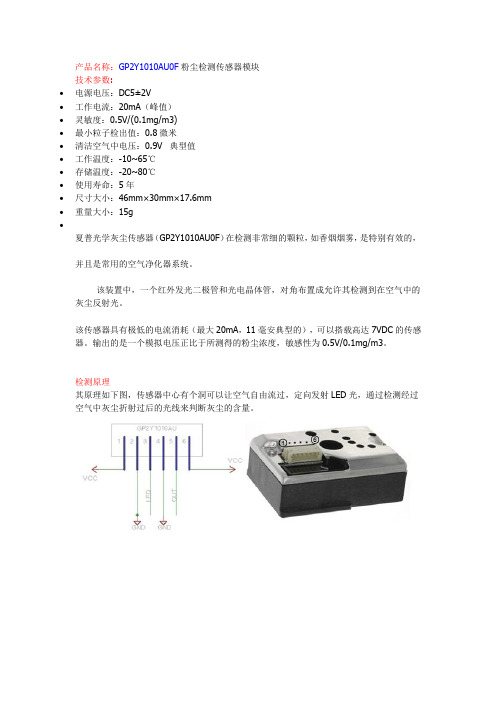
产品名称:GP2Y1010AU0F粉尘检测传感器模块
技术参数:
∙电源电压:DC5±2V
∙工作电流:20mA(峰值)
∙灵敏度:0.5V/(0.1mg/m3)
∙最小粒子检出值:0.8微米
∙清洁空气中电压:0.9V 典型值
∙工作温度:-10~65℃
∙存储温度:-20~80℃
∙使用寿命:5年
∙尺寸大小:46mm×30mm×17.6mm
∙重量大小:15g
∙
夏普光学灰尘传感器(GP2Y1010AU0F)在检测非常细的颗粒,如香烟烟雾,是特别有效的,
并且是常用的空气净化器系统。
该装置中,一个红外发光二极管和光电晶体管,对角布置成允许其检测到在空气中的灰尘反射光。
该传感器具有极低的电流消耗(最大20mA,11毫安典型的),可以搭载高达7VDC的传感器。
输出的是一个模拟电压正比于所测得的粉尘浓度,敏感性为0.5V/0.1mg/m3。
检测原理
其原理如下图,传感器中心有个洞可以让空气自由流过,定向发射LED光,通过检测经过空气中灰尘折射过后的光线来判断灰尘的含量。
基于 STM32的空气净化器控制系统
基于 STM32的空气净化器控制系统赵玉敏;宋开新;秦会斌【摘要】设计了一种电压可调式静电除尘装置结合紫外灯杀菌消毒的家用空气净化器控制系统。
系统采用低功耗的32位微处理器STM32F103RCT6作为主控芯片,利用DHT11温湿度传感器、GP2Y1010AU0F灰尘传感器和TGS2600气体传感器检测室内空气质量,将采集到的数据传输给单片机,并显示到TFTLCD液晶屏上。
单片机根据接收到的数据采用按键或蓝牙来调整电机风速、电压以及紫外灯的开关等,使空气净化器处于最佳工作状态。
该系统经过调试,运行稳定,效果明显。
%An home air purifier control system is designed in this paper , which use adjustable voltage electrostatic dust removal device ,com-bined with UV to disinfect .Low-power 32-bit microprocessor as the core , the application of temperature and humidity sensor DHT 11 ,dust sen-sorGP2Y and air sensor TGS2600 in the detection of indoor environment , the collected data will transfer to the SCM ,and display on TFTLCD. SCM using button or bluetooth to adjust the wind speed and voltage of the air purifier in the best working condition according to the received da -ta.After commissioning ,we get a stable and significant effect system .【期刊名称】《微型机与应用》【年(卷),期】2016(035)023【总页数】4页(P24-27)【关键词】STM32单片机;传感器;紫外线;蓝牙;静电集尘装置【作者】赵玉敏;宋开新;秦会斌【作者单位】杭州电子科技大学新型电子器件与应用研究所,浙江杭州310018;杭州电子科技大学新型电子器件与应用研究所,浙江杭州310018;杭州电子科技大学新型电子器件与应用研究所,浙江杭州310018【正文语种】中文【中图分类】TP23空气净化器技术是现代工业发展逐步形成的技术。
使用夏普GP2Y1010AU0F灰尘传感器检测空气质量..

使用夏普GP2Y1010AU0F灰尘传感器检测空气质量夏普灰尘传感器价格较便宜,能检测出室内空气中的灰尘和烟尘含量.检测原理其原理如下图,传感器中心有个洞可以让空气自由流过,定向发射LED光,通过检测经过空气中灰尘折射过后的光线来判断灰尘的含量。
电路图因为数据是通过pin 5的电压模拟信号输出的,而树莓派的引脚不支持模拟信号直接读取(需要增加数模转换芯片),所以先用Arduino来实验。
Arduino 代码根据电路图,把Arduino和传感器连接起来:1.Sharp pin 1 (V-LED) => 5V 串联1个150欧姆的电阻(最好在电阻一侧和GND之间再串联一个220uf的电容)2.Sharp pin 2 (LED-GND) => GND3.Sharp pin 3 (LED) => Arduino PIN 2 (开关LED)4.Sharp pin 4 (S-GND) => GND5.Sharp pin 5 (Vo) => Arduino A0 pin (空气质量数据通过电压模拟信号输出)6.Sharp pin 6 (Vcc) => 5V1./*2.Interface to Sharp GP2Y1010AU0F Particle Sensor3.Program by Christopher Nafis4.Written April 20125.6.7.8.9.Sharp pin 1 (V-LED) => 5V (connected to 150ohm resister)10.Sharp pin 2 (LED-GND) => Arduino GND pin11.Sharp pin 3 (LED) => Arduino pin 212.Sharp pin 4 (S-GND) => Arduino GND pin13.Sharp pin 5 (Vo) => Arduino A0 pin14.Sharp pin 6 (Vcc) => 5V15.*/16.#include<SPI.h>17.#include<stdlib.h>18.19.int dustPin=0;20.int ledPower=2;21.int delayTime=280;22.int delayTime2=40;23.float offTime=9680;24.25.int dustVal=0;26.int i=0;27.float ppm=0;28.char s[32];29.float voltage=0;30.float dustdensity=0;31.float ppmpercf=0;32.33.void setup(){34.Serial.begin(9600);35. pinMode(ledPower,OUTPUT);36.37.// give the ethernet module time to boot up:38. delay(1000);39.40. i=0;41. ppm=0;42.}43.44.void loop(){45. i=i+1;46. digitalWrite(ledPower,LOW);// power on the LED47. delayMicroseconds(delayTime);48. dustVal=analogRead(dustPin);// read the dust value49. ppm=ppm+dustVal;50. delayMicroseconds(delayTime2);51. digitalWrite(ledPower,HIGH);// turn the LED off52. delayMicroseconds(offTime);53.54. voltage=ppm/i*0.0049;55. dustdensity=0.17*voltage-0.1;56. ppmpercf=(voltage-0.0256)*120000;57.if(ppmpercf<0)58. ppmpercf=0;59.if(dustdensity<0)60. dustdensity=0;61.if(dustdensity>0.5)62. dustdensity=0.5;63.String dataString="";64. dataString+=dtostrf(voltage,9,4,s);65. dataString+=",";66. dataString+=dtostrf(dustdensity,5,2,s);67. dataString+=",";68. dataString+=dtostrf(ppmpercf,8,0,s);69. i=0;70. ppm=0;71.Serial.println(dataString);72. delay(1000);73.}把传感器和Ardiuno连接好后,可以连续打印出传感器的输出电压值。
一种基于某51单片机地粉尘监测系统地设计—定稿子

届.别.2016届学号毕业设计基于51单片机的PM2.5检测系统的设计与实现姓名系别、专业电子信息与电气工程学院电子信息科学与技术专业导师姓名、职称完成时间 2016年5月10日目录摘要 (I)Abstract (I)1 绪论 (1)1.1 课题背景 (1)1.2 国内外研究现状 (1)2 系统仿真软件与总体设计方案 (1)2.1 Keil4软件开发坏境 (1)2.2 软件烧录工具 (2)2.3程序结构分析 (4)2.4 整体的设计方案 (4)2.5电源模块 (4)3 主要元器件简介43.1 GP2Y1010AU0F传感器简介 (5)3.2 ADC0832模数转换器简介 (7)3.3 LCD1602液晶显示屏 (10)3.4 STC89C52单片机的简介 (12)4 系统单元电路模块设计 (15)4.1主控制模块 (15)4.2显示模块电路 (16)4.3关于报警模块的设计 (16)4.4按键模块的设计 (17)4.5粉尘模块电路设计 (17)4.6电源局部的设计 (17)5 系统测试与实现 (18)5.1系统程序流图 (18)5.2 仿真电路 (20)5.3 软件跟硬件结合 (21)5.4 测试结果分析 (23)5.5 系统实现 (23)6、总结 (24)致谢 (24)参考文献 (25)附录1:系统整体电路原理图 (26)附录2:系统设计局部源程序 (27)摘要现在社会开展的越来越快,随着工业的开展,虽然给人们的生活带来很多便利。
但是,在生产过程产生很多对人体有害的因素工业生产过程中会,例如煤炭灰开采、水泥生产等行业中的粉尘污染。
我的设计采用由LCD1602液晶模块、STC89C52单片机最小系统、ADC0832模数转换器模块、GP2Y1010AU粉尘传感器、电源模块、蜂鸣器报警模块和按键模块模块组成。
单片机是通过ADC0832转换芯片采集GP2Y1010AU粉尘传感器的粉尘的浓度,通过单片机的数据转换处理后在液晶屏上显示空气中的质量,测量空间中的粉尘浓度如果大于当时设置粉尘浓度时,蜂鸣器就会产生报警的声音和发光二极管发出声光报警。
pm2.5传感器四种工作原理及进口品牌介绍

pm2.5传感器四种工作原理及进口品牌介绍工采网小编从原理出发介绍当下pm2.5传感器应用普遍,进口品牌较多的综合评测、方便集成采用选型原理介绍:1,光散射法光散射原理有LED光(普通光学),激光等原理,传感器可以有效的探测出粒径约0.5um 以上颗粒,至此光散射法听着可靠性相对较低,然而又由于光散射原理探头相对便宜,探头易安装,使用,做为监测应用相对合适,相对其它原理有较多的优势,且应用商选择质量较好,并相对稳定,灵敏的探头,数据可靠性大大增加!目前市面上光散射法应用成熟普遍,是pm2.5监测的较好选择!2、重量法我国目前对大气颗粒物的测定主要采用重量法。
其原理是分别通过一定切割特征的采样器,以恒速抽取定量体积空气,使环境空气中的PM2.5和PM10被截留在已知质量的滤膜上,根据采样前后滤膜的质量差和采样体积,计算出PM2.5和PM10的浓度。
必须注意的是,计量颗粒物的单位ug/m3 中分母的体积应该是标准状况下(0℃、101.3kPa)的体积,对实测温度、压力下的体积均应换算成标准状况下的体积。
环境空气监测中采样环境及采样频率要按照HJ.T194的要求执行。
PM10连续自动监测仪的采样切割装置一般设计成旋风式,它在规定的流量下,对空气中10um粒径的颗粒物具有50%的采集效率、以下为其技术性能指标表。
3、微量振荡天平法TEOM微量振荡天平法是在质量传感器内使用一个振荡空心锥形管,在其振荡端安装可更换的滤膜,振荡频率取决于锥形管特征和其质量。
当采样气流通过滤膜,其中的颗粒物沉积在滤膜上,滤膜的质量变化导致振荡频率的变化,通过振荡频率变化计算出沉积在滤膜上颗粒物的质量,再根据流量、现场环境温度和气压计算出该时段颗粒物标志的质量浓度。
微量振荡天平法颗粒物监测仪由PM10采样头、PM2.5切割器、滤膜动态测量系统、采样泵和仪器主机组成。
流量为1m3/h环境空气样品经过PM10采样头和PM2.5切割器后,成为符合技术要求的颗粒物样品气体。
GP2Y1010AU0FC0L模块使用说明书

开发控制板组成,
GP2Y1010AU0FC01模块使用说明书
一, 简介
1,该模块由夏普粉尘传感器GP2Y1010AU0F 和模块型号是:GP2Y1010AU0FC01,模块经过精确标定后,检测空气中的粉尘浓度,精度高,一致性强。
2,传感器智能校准:当灰尘附着于传感器或传感器老化时,系统会自动进行浓度参数校准,确保测量的准确性。
3,提供多种浓度值输出接口:模拟电压输出:灰尘浓度越高,输出模拟电压越高。
数字串口输出;供其它平台MCU 直接读取。
二,接线图
第一脚:5V 工作电压输入端
第二脚:串口数据输出
第三脚:串口数据输入
第四脚:灰尘浓度模拟电压输出
第五脚:不用连接
第六脚:工作电压地
三,技术参数
四,通信协议命令格式
1,模块读取除尘机工作状态:
传感器发送命令格式:05FEF603
除尘机收到上述命令后返回工作状态
①除尘机处于开机状态:返回数据格式06FEF103
②除尘机处于关机状态:返回数据格式06FEF003
2,除尘机读取灰尘浓度值:
除尘机发送命令格式:05FEF503
模块收到上述指令后返回浓度值。
返回数据格式:06ABCD03
浓度计数方法:浓度值(十六进制)=0XABCD(ug/m3)。
例如AB=01,CD=0X23:则
浓度(十六进制)=0X0123(ug/m3)
浓度(十进制)=291(ug/m3)。
自制pm2.5检测仪资料

由项目实例从零开始学arduino系列(一)项目:利用arduino自制pm2.5检测仪目的:通过自制pm2.5检测仪过程掌握arduino 控制板接口电路,1602液晶显示屏连接arduino 控制板显示技术,相关arduino编程语言,灰尘传感器连接arduino控制板方法。
知识点:1602液晶显示,灰尘传感器接法,基础的arduino编程语言。
白话文式讲解一、硬件连接(图在详细讲解处)(一)粉尘传感器连接nano板SHARP GP2Y1010AU0F型灰尘/粉尘传感器的红色线为6号线,向左依次为5,4,3,2,1号线。
粉尘传感器6号线接Arduinonano板的5V端。
粉尘传感器5号线接Arduinonano板的A0端。
粉尘传感器4号线接Arduinonano板的GND端。
粉尘传感器3号线接Arduinonano板的D2端。
粉尘传感器2号线接Arduinonano板的GND端。
粉尘传感器1号线接150欧姆电阻和220uF的电解电容正极,150欧姆电阻的另一端接Arduinonano板的5V端。
220uF的电解电容负极接Arduinonano板的GND端。
(二)1602液晶屏连接nano板1602液晶屏上标有数字针脚,一般是16针。
我们用到了12个针脚。
液晶屏第16针连接Arduinonano板的GND端。
液晶屏第15针连接Arduinonano板的5V端。
液晶屏第14针连接Arduinonano板的D6端。
液晶屏第13针连接Arduinonano板的D7端。
液晶屏第12针连接Arduinonano板的D8端。
液晶屏第11针连接Arduinonano板的D9端。
液晶屏第1针连接Arduinonano板的GND端。
液晶屏第2针连接Arduinonano板的5V端。
液晶屏第3针先接1k电阻,电阻另一端连接Arduinonano板的D6端。
液晶屏第4针连接Arduinonano板的D12端。
液晶屏第5针连接Arduinonano板的D11端。
- 1、下载文档前请自行甄别文档内容的完整性,平台不提供额外的编辑、内容补充、找答案等附加服务。
- 2、"仅部分预览"的文档,不可在线预览部分如存在完整性等问题,可反馈申请退款(可完整预览的文档不适用该条件!)。
- 3、如文档侵犯您的权益,请联系客服反馈,我们会尽快为您处理(人工客服工作时间:9:00-18:30)。
GP2Y1010AU0F1Sheet No.: E4-A01501ENDate Dec. 1. 2006© SHARP CorporationGP2Y1010AU0FCompact Optical Dust Sensor■ Description■Features■ Compliance■Applications1. Detecting of dust in the air.2. Example: Air purifier, Air conditioner, Air monitor1. Compliant with RoHS directive (2002/95/EC1. Compact, thin package (46.0 × 30.0 × 17.6 mm2. Low consumption current (Icc: MAX. 20 mA3. The presence of dust can be detected by the photometry of only one pulse4. Enable to distinguish smoke from house dust5. Lead-free and RoHS directive compliantNotice The content of data sheet is subject to change without prior notice.In the absence of confirmation by device specification sheets, SHARP takes no responsibility for any defects that may occur in equipment using any SHARP devices shown in catalogs, data books, etc. Contact SHARP in order to obtain the latest device specification sheets before using any SHARP device.GP2Y1010AU0F is a dust sensor by optical sensing system.An infrared emitting diode (IRED and an phototran-sistor are diagonally arranged into this device.It detects the reflected light of dust in air.Especially, it is effective to detect very fine particle like the cigarette smoke.In addition it can distinguish smoke from house dustby pulse pattern of output voltage.2Sheet No.: E4-A01501ENGP2Y1010AU0F■ Internal schematic ■ Outline Dimensions (Unit : mmV-LEDLED-GND LED S-GND V O V CC 1234561326543Sheet No.: E4-A01501ENGP2Y1010AU0Frepeats in a 10 year cycle Marking informationCountry of originPhilippinesDate code (2 digit1st digit2nd digitYear of productionMonth of productionA.D. Mark Month Mark 2000011200112220022332003344200445520055662006677200778820088992009910X 2010011Y ::12Z4Sheet No.: E4-A01501ENGP2Y1010AU0F■ ■ Absolute Maximum Ratings*1 Open drain drive inputParameter Symbol Rating Unit Supply voltageCC V Operating temperatureT T opr −10 to +65°C −0.3 to VCC V −0.3 to +7Input terminal voltageV V LED *1Soldering temperaturesol−20 to +80°CElectro-optical Characteristics■ Recommended input condition for LED input terminalParameter ConditionsSymbol K V OC I LED *1 *2 *3*2 *3*2 *3RL =4.7k Ω*2LED terminal voltage = 0*2RL =∞MIN. 0.3503.4−−TYP. 0.50.9−1110MAX. 1.50.65−2020Unit V/(0.1mg/m3V V mA mASensitivityOutput voltage at no dustV OH Output voltage rangeLED terminal currentI CCConsumption current*1 Sensitivity is specified by the amount of output voltage change when dust density changes by 0.1 mg/m3.And the dust density for detection is a value of the density of cigarette (MILD SEVEN® smoke measured by the digital dust monitor (P-5L2: manufactured by SHIBATA SCIENTIFIC TECHNOLOGY LTD..*2 Input condition is shown in Fig. 1*3 Output sampling timing is shown in Fig. 2 (Ta =25°C(Ta =25°C, VCC =5VParameterPulse CyclePulse WidthOperating Supply voltageSymbol T P W V CCValue 10 ± 10.32 ± 0.025 ± 0.5Unit ms ms VFig. 1 Input Condition for LED Input TerminalFig. 2 Sampling Timing of Output PulseI LED5Sheet No.: E4-A01501ENGP2Y1010AU0FRemarks : Please be aware that all data in the graph are just for reference and are not for guarantee.432100.20.40.60.8O u t p u t v o l t a g e (VDust density (mg/m3Fig. 3 Output Voltage vs. Dust DensityGP2Y1010AU0F ● No tes 1 Connection of case and GND Case material use conductive resin as cover case {printed model No.} and metal {test terminal side} as bottom cover. The metal case connects with GND in sensor. 2 Cleaning Please don’t do cleaning, because there is a case that this device is not satisfied with its characteristics by cleaning. 3 Pulse input range Please subject to recommendation as regard input condition for LED in order to keep reliability. 4 Dust adhesion There is a case that this product does not detect the dust density correctly, since the dust adhered to the inside of the dust through hole may project into the detecting space which consist of emitter and detector light axis. Please take the structure and mechanism of the equipment into consideration to avoid the influence of adhered dust. And when the dust is adhered, please consider themaintenance such as vacuuming or blowing off the dust by air. In addition, please pay attention to structure and placing location of the application to avoid any adhesive particle like oil, etc. to gets into the device. If it sticks to optical part, malfunction may occur. 5 Light output In circuit designing, make allowance for the degradation of the light emitting diode output that results from long continuous operation. (50% degradation/5 years 6 Sensitivity adjustment VR VR for sensitivity adjustment is set up at shipping from sharp. Please do not touch the VR or Electro-optical characteristics specified on the specification will be invalid. 7 Resolution Please do not disassemble the device such as removing tapping screw and so on. Even if the device is reassembled, it may not satisfy the specification. 8 Application to fire alarm Please do not use this device for a fire alarm application. When using this device to application other than air purifying and equipment with air purifying function, please inform us before usage. 9 Noise influence If the sensor is located close to noise generator (ex. Electric dust collector, etc. , the sensor output may be affected by leaded noise. On top of that noise from power supply line also may affect the sensor output. When desinging the system, please consider the effect from noise. 10 Vibration influence The sensor may change its value under mechanical oscillation. Before usage, please make sure that the device works normally in the application. 11 Incident light influence There is a case that the sensor output may be affected when outer-light comes through dust through hole on printed side. In order to avoid any influence from outer-light, please locate the printed side of sensor facing to inside of the application. 12 When inside of the sensor is moisturized, this product does not keep its proper function. Please design the application so that moisturization of the sensor does not happen. Sheet No.: E4-A01501EN 6GP2Y1010AU0F ● Presence of ODC etc. This product shall not contain the following materials. And they are not used in the production process for this product. Regulation substances : CFCs, Halon, Carbon tetrachloride, 1.1.1-Trichloroethane (Methylchloroform Specific brominated flame retardants such as the PBB and PBDE are not used in this product at all. This product shall not contain the following materialsbanned in the RoHS Directive (2002/95/EC. • Lead, Mercury, Cadmium, Hexava lent chromium, Polybrominated biphenyls (PBB, Polybrominated diphenyl ethers (PBDE. Sheet No.: E4-A01501EN 7GP2Y1010AU0F Packing Specification Pad Product trays (5 trays/case Connector Product (B Packing case Packing tape Tray (A (C Model number Quantity Inspection date PACKING METHOD 1. Each tray holds 50 pieces. Packing methods are shown in (A. 2. Each box holds 5 trays. Pads are added to top (B. 3. The box is sealed with packing tape. (C shows the location of the Model number, Quantity, and Inspection date. 4. Weight is approximately 5.6 kg Sheet No.: E4-A01501EN 8GP2Y1010AU0F ■ Important Notices · The circuit application examples in this publication are provided to explain representative applications of SHARP devices and are not intended to guarantee any circuit design or license any intellectual property rights. SHARP takes no responsibility for any problems related to any intellectual property right of a third party resulting from the use of SHARP's devices. · Contact SHARP in order to obtain the latest device specification sheets before using any SHARP device. SHARP reserves the right to make changes in the specifications, characteristics, data, materials, structure, and other contents described herein at any time without notice in order to improve design or reliability. Manufacturing locations are also subject to change without notice. · Observe the following points when using any devices in this publication. SHARP takes no responsibility for damage caused by improper use of the devices which does not meet the conditions and absolute maximum ratings to be used specified in the relevant specification sheet nor meet the following conditions: (i The devices in this publication are designed for use in general electronic equipment designs such as: --- Personal computers --- Office automation equipment --- Telecommunication equipment [terminal] --- Test and measurement equipment --- Industrial control --- Audio visual equipment --- Consumer electronics (ii Measures such as fail-safe function and redundant design should be taken to ensure reliability and safety when SHARP devices are used foror in connection with equipment that requires higher reliability such as: --- Transportation control and safety equipment (i.e., aircraft, trains, automobiles, etc. --- Traffic signals --- Gas leakage sensor breakers --- Alarm equipment --- Various safety devices, etc. (iii SHARP devices shall not be used for or in connection with equipment that requires an extremely high level of reliability and safety such as: --- Space applications --- Telecommunication equipment [trunk lines] --- Nuclear power control equipment --- Medical and other life support equipment (e.g., scuba. · If the SHARP devices listed in this publication fall within the scope of strategic products described in the Foreign Exchange and Foreign Trade Law of Japan, it is necessary to obtain approval to export such SHARP devices. · This publication is the proprietary product of SHARP and is copyrighted, with all rights reserved. Under the copyright laws, no part of this publication may be reproduced or transmitted in any form or by any means, electronic or mechanical, for any purpose, in whole or in part, without the express written permission of SHARP. Express written permission is also required before any use of this publication may be made by a third party. · Contact and consult with a SHARP representative if there are any questions about the contents of this publication. Sheet No.: E4-A01501EN 9。