开始体验STM-STUDIO
MICROSOFTVISUALSTUDIO入门经典教程

MICROSOFTVISUALSTUDIO入门经典教程Microsoft Visual Studio是一款常用的集成开发环境(IDE),广
泛用于开发各种类型的应用程序,包括桌面应用、Web应用、移动应用等。
本文将为读者介绍Visual Studio的基本概念和使用方法。
Visual Studio提供了丰富的功能和工具,使开发过程更高效和便捷。
在开始使用Visual Studio之前,需要先了解一些基本概念和术语。
在编写程序时,可以使用Debug功能进行调试。
可以设置断点,在程
序执行到断点处停下来,检查变量的值、跟踪程序的执行流程等。
可以逐
步执行程序,查看每一步的结果。
在Visual Studio中,还可以进行版本控制,使用工具如Git或
Team Foundation Server进行代码管理。
版本控制可以帮助团队成员协
同开发,追踪每一次代码更改。
在提交或发布程序之前,可以进行性能分析和代码检查。
Visual Studio提供了Performance Profiler和Code Analysis工具,帮助开发
者优化程序性能和提高代码质量。
总之,Visual Studio是一款功能强大的开发工具,可以大大提高软
件开发的效率和质量。
通过学习和掌握Visual Studio的基本使用方法,
可以更好地进行项目开发。
希望读者通过本文的介绍,对Visual Studio
有一个初步了解,能够使用Visual Studio进行开发工作。
使用studio创建出的流程

使用Studio创建出的流程简介在软件开发和数据分析中,使用流程图可以清晰地表示出一个系统或者一个过程的运行流程。
而在使用Studio进行流程设计时,可以更加高效地创建出管理和自动化各种业务流程的工作流。
熟悉Studio界面在开始创建流程之前,需要先熟悉Studio的界面。
Studio是一个集成开发环境,提供了可视化的流程设计器和各种工具、控件来支持流程的设计和管理。
在打开Studio后,会看到一个主界面,主界面由多个区域组成,包括工具栏、属性窗口、流程设计器窗口等。
创建流程创建流程的第一步是点击Studio界面上的“新建流程”按钮。
在弹出的对话框中,可以选择不同的流程模板。
Studio提供了多种不同类型的流程模板,包括顺序流程、并行流程、条件流程等。
选择适合自己需求的流程模板后,点击“确定”按钮。
设计流程设计流程主要是在流程设计器中进行的。
流程设计器是一个可视化的界面,可以通过拖拽控件、连线等方式来设计流程。
在Studio中,每个流程由多个步骤组成,每个步骤可以包含一个或多个操作。
常见的操作包括数据读取、数据处理、数据分析、数据输出等。
接下来,我们以创建一个简单的数据处理流程为例,来详细介绍如何使用Studio进行流程设计。
步骤一:添加步骤首先,在流程设计器中,点击“添加步骤”按钮。
在弹出的对话框中,可以选择不同的步骤类型。
在这个例子中,我们选择“数据读取”步骤来读取待处理的数据。
点击“确定”后,一个新的步骤就会被添加到流程中。
步骤二:配置步骤接下来,双击新添加的步骤,在属性窗口中进行配置。
在这个例子中,我们需要配置数据读取的参数,如文件路径、文件格式等。
根据具体需求进行配置后,点击“确定”。
步骤三:添加操作在步骤一的基础上,我们可以继续添加其他步骤和操作来实现更复杂的流程。
例如,我们可以添加一个“数据处理”步骤来对读取的数据进行处理,再添加一个“数据输出”步骤将处理结果输出到指定的文件中。
步骤四:链接步骤在设计流程时,各个步骤之间的顺序和逻辑非常重要。
Teams App Studio的应用开发技巧
Teams App Studio的应用开发技巧Teams App Studio的应用开发技巧随着微软微信团队合作推出的Teams应用逐渐成为企业办公生活的必备工具,Teams App Studio作为一款专门为Teams应用开发者设计的工具也日益受到关注与使用。
Teams App Studio可以帮助开发者快速创建适用于Teams的应用程序,并且能够做到从编码到测试一条龙服务,大大降低了应用的开发难度和复杂度。
本文旨在介绍Teams App Studio的应用开发技巧,为开发者提供有关应用程序开发的参考。
一、应用程序架构在创建任何应用程序之前,首先需要定义应用程序架构。
应用程序架构是应用程序的基础,它会直接影响后期功能扩展和更新时的易用性和可维护性。
在Teams App Studio中,应用程序由三个主要组件组成,分别是Bot、消息扩展和选项卡,它们分别对应着应用程序的不同功能。
1. BotBot是Teams应用程序的主要功能之一。
Bot可以通过聊天窗口与用户交互,响应用户的请求,执行自动化任务等。
在创建Bot时,可以为其定义关键字,这些关键字在用户通讯时可以触发Bot的特定功能。
同时还可以通过与Azure Bot Service集成来为Bot实现更多的功能,比如调用第三方API、应用程序的身份验证和存储数据等。
2.消息扩展消息扩展可以让用户在消息中嵌入多媒体内容,比如图片、视频、链接等。
通过使用消息扩展,可以让用户更快地获取消息中的相关信息,同时也可以丰富用户的使用体验。
消息扩展的主要优点是可以将外部应用程序中的内容嵌入到Teams中,包括其他微软Apps和第三方服务。
3.选项卡选项卡可以让用户更轻松地进行导航并查看注释性数据。
选项卡是通过定义与应用程序相关的自定义HTML内容来创建的。
选项卡可以包括各种不同的元素,包括表格、文本框、图表等。
二、应用程序开发流程1.创建应用程序在创建应用程序之前,需要确定应用程序的主要功能和目标用户。
安卓studio使用教程
安卓studio使用教程安卓Studio是谷歌推出的集成开发环境,用于开发安卓应用程序。
它提供了一系列强大的工具和功能,可以帮助开发人员创建、调试和部署高质量的安卓应用。
以下是安卓Studio的使用教程,简单介绍了如何使用该工具进行安卓应用程序开发。
第一步:安装安卓Studio要开始使用安卓Studio,需要首先在计算机上安装该软件。
可以从谷歌的开发者网站下载最新版本的安卓Studio。
下载完成后,双击安装程序,并按照提示完成安装。
第二步:创建新项目安装完成后,打开安卓Studio。
在欢迎界面上,选择“创建新项目”,然后按照向导的指示进行操作。
在创建新项目时,可以选择使用空项目模板,或者根据自己的需求选择其他模板。
第三步:设计界面在安卓Studio中,可以使用XML布局文件来设计应用程序的用户界面。
可以在工具栏中选择所需的视图元素,然后将其拖放到编辑器中。
可以通过调整元素的属性来自定义界面的外观和行为。
第四步:添加功能安卓Studio提供了一系列开发工具和API,可以轻松地添加各种功能到应用程序中。
可以使用Java或Kotlin编写代码,实现应用程序的逻辑和功能。
可以使用内置的代码编辑器来编写代码,并进行调试和测试。
第五步:编译和调试在完成代码编写后,可以通过安卓Studio进行应用程序的编译和调试。
可以选择在模拟器或真实设备上运行应用程序,并检查其行为和性能。
安卓Studio提供了一系列调试工具,可以帮助开发人员查找和修复潜在的问题。
第六步:构建和部署在应用程序开发完成之后,可以使用安卓Studio进行构建和部署。
可以选择生成APK文件,以便在真实设备上安装和运行应用程序。
可以选择发布应用程序到谷歌Play商店,以便其他用户下载和使用。
总结:安卓Studio是一个功能强大的开发工具,可以帮助开发人员轻松地创建、调试和部署安卓应用程序。
本教程简单介绍了使用安卓Studio的基本步骤,包括安装、创建项目、设计界面、添加功能、编译和调试、构建和部署等。
AtmelStudio-60简易入门教程(精炼实用)

、建议工程文件AtmeIStUdi6.0这个全新的环境使用起来极其不顺手,因为首先我对AtmeIStUdiO以前的版本也根本没有使用经验,就根据很陌生,其次,这个新版本软件还根本没有人用,根本没有任何的相关教程资料,唯一可以参考的只是官网的比较简单的视频教程,还是英文讲解,反正没怎么搞透。
不过还是硬着头皮用下去,因为软件是免费的,而且当后來我知道代码编辑环境其实就是微软VS环境的时候,我就更不犹豫了,大家应该都了解VS的代码编写环境是很智能的,尤其自动补全功能。
现在,我己经能很熟练的使用AtmelSUdio6.0软件了,随若使用我也更加喜欢玩AVR单片机做一些小作品了,而不再用普通51和SrC了。
当使用熟练以后也就感觉到其实这个免费智能的编译环境其实是很简单的,那现在我就帮助更多喜欢使用AVR而没用使用AtmeIStUCliO软件的同学们轻松越过这一个门槛,进入一个美好的编程世界。
该软件的不足之处:一是软件相对较大,打开比较慢,但是运行还是比较顺利的;二是不支持山寨仿真器,这可苦了没钱的劳苦电工们了。
(不过我都是用ISP烧求调试,一般不用仿真)最下而附件有一个简单的LED_test工程文件,编译通过的。
大家可以试用。
下面开始介绍的软件工程的建立。
1. 软件总界面总体界面还是比较简洁的,和其他编译软件都是差不多的,而Jl•和KEIL软件的界面是很相似的,使用很方便。
•SiΛPage・.:m∙Ytvdkl‰dπvΛ⅞r∙Mo<ι曰T W rWV,Mι⅛t×ΛΛfPrqeCtOaQTOd‰WirHRPJj∙4)JfiJr¾ɔ⅛∙'∙';TJ Clo$«NKafterProxet⅛>ad J S*>OWp»®ecoy∣owCUtPHt⅛oαr2. 新建工程新建工程很简单:FlLE->NEW->Project然后就看到下而的新建工程界而了,选择第一个GCCCEXeCUtabIeTS就可以,第二个GcCCStatiCLibrary是用來新建.h文件的。
VisualStudio使用入门教程
VisualStudio使用入门教程第一章:介绍和安装VisualStudio是由Microsoft开发的一款集成开发环境(IDE),适用于多种编程语言。
它提供了丰富的工具和功能,使开发人员能够更轻松地创建、调试和部署应用程序。
1.1 为什么选择VisualStudio- VisualStudio支持多种编程语言,包括C#、C++、等,适用于不同的开发需求。
- 具有强大的代码编辑、调试和测试工具,能够提高开发效率。
- 集成了一系列的扩展和插件,可以按需定制开发环境。
- 兼容性好,能够与其他Microsoft产品和平台无缝集成。
1.2 下载和安装- 访问Microsoft官方网站,选择合适的版本下载(社区版、专业版或企业版)。
- 执行安装程序,按照提示进行安装。
- 安装完成后,启动VisualStudio,进行初步配置。
第二章:项目和解决方案在VisualStudio中,项目是代码和相关文件的集合,解决方案则是包含一个或多个项目的集合。
在开始开发应用程序之前,需要先创建项目和解决方案。
2.1 创建项目- 打开VisualStudio,选择“文件” -> “新建” -> “项目”。
- 在“模板”中选择合适的项目类型,比如Windows Forms应用程序、网站等。
- 设置项目名称、位置和其他相关选项,点击“确定”完成项目创建。
2.2 添加文件- 打开已有项目,选择“项目” -> “添加新项”。
- 在弹出的对话框中选择合适的文件类型,并设置文件名称。
- 文件添加完成后,在解决方案资源管理器中可以看到新增文件。
第三章:编辑和调试VisualStudio提供了强大的代码编辑和调试功能,帮助开发人员快速编写和调试代码。
3.1 代码编辑- 在VisualStudio编辑器中打开文件,可以看到代码的语法高亮、自动补全和智能感知等功能。
- 使用快捷键或右键菜单,可以进行复制、粘贴、查找替换等常用操作。
visual studio 开发工具使用方法
visual studio 开发工具使用方法如何使用Visual Studio开发工具。
第一步:安装Visual Studio在使用Visual Studio之前,我们首先需要安装它。
首先,从Visual Studio的官方网站上下载适合你的操作系统的安装程序。
一旦下载完成,运行安装程序,按照提示进行安装。
在安装过程中,你可以选择安装的组件,例如使用C++进行开发或使用Web开发工具。
你还可以选择你想要的开发环境,如使用C,C++或Visual Basic进行开发。
完成安装后,Visual Studio将准备就绪。
第二步:创建一个新项目打开Visual Studio后,你会看到一个欢迎界面。
这个界面上有一些常用的选项,如最近打开的项目和创建新项目。
点击“创建新项目”选项,然后选择适合你的项目模板。
Visual Studio提供了许多常用的项目模板,如控制台应用程序、Windows应用程序、Web 应用程序等。
选择一个模板后,你可以为项目选择一个名称和位置。
点击“确定”按钮后,Visual Studio将为你创建一个新项目。
第三步:编写代码一旦你的项目创建完成,你就可以开始编写代码了。
Visual Studio提供了一个集成的开发环境,包括代码编辑器、调试器和一些辅助工具。
在代码编辑器中,你可以编写代码并添加注释。
在编辑器的左侧,你可以看到代码的结构,如类、方法和变量。
在编辑器的右侧,你可以看到一些辅助工具,如错误列表、属性窗口和解决方案资源管理器。
你可以使用这些工具来辅助你的开发工作。
第四步:编译和运行项目在编写完代码后,你需要编译和运行你的项目以验证你的代码是否按预期工作。
你可以点击工具栏上的“生成”按钮来编译你的项目。
编译完成后,如果没有错误,你可以点击“调试”按钮来运行你的项目。
Visual Studio将启动调试器,并在调试窗口中显示你的项目的运行状态。
你可以逐步执行代码,查看变量的值和执行过程中的错误。
STM的开发环境及工具介绍
STM的开发环境及工具介绍随着科技的进步,嵌入式系统在各行各业中的应用越来越广泛。
STM32是一款由意法半导体(STMicroelectronics)推出的32位嵌入式开发平台,它以其高性能、低功耗和丰富的外设特性而备受开发者的青睐。
为了更好地开发STM32系列芯片,合适的开发环境和工具是必不可少的。
本文将为您介绍STM的开发环境及相关工具。
一、开发环境介绍1. STM32CubeIDESTM32CubeIDE是由STMicroelectronics开发的一款集成开发环境(IDE),旨在为STM32系列提供全面的开发工具。
它基于Eclipse开发框架,提供了强大的代码编辑、编译、调试和仿真功能。
同时,STM32CubeIDE还集成了STM32Cube软件包,可以帮助开发者快速构建应用程序。
2. Keil MDKKeil MDK是一款流行的嵌入式开发环境,适用于多种ARM架构的微控制器系列。
它支持对STM32芯片的开发,并且提供了易于使用的图形化界面和强大的调试功能。
Keil MDK还包含了一套全面的开发工具,如编译器、链接器和调试器,方便开发者进行全面的开发任务。
二、常用工具介绍1. STM32CubeMXSTM32CubeMX是一款图形化配置工具,它可以帮助开发者快速生成STM32系列的初始代码框架。
通过选择硬件外设和配置参数,开发者可以轻松生成C代码,并且可以方便地导入到开发环境中进行二次开发。
STM32CubeMX还可以自动生成初始化代码和驱动程序,大大简化了开发流程。
2. ST-Link调试器ST-Link是一款常用的调试器和编程器,适用于STM32开发。
它可以通过USB接口与开发板进行连接,并提供了调试和编程的功能。
ST-Link调试器支持多种调试接口,如JTAG和SWD,可支持各种调试需求。
开发者可以借助ST-Link调试器进行程序的烧录、调试和性能分析,提高开发效率。
3. STM32Cube软件包STM32Cube软件包是由STMicroelectronics提供的一套软件资源集合,旨在简化STM32芯片的开发。
- 1、下载文档前请自行甄别文档内容的完整性,平台不提供额外的编辑、内容补充、找答案等附加服务。
- 2、"仅部分预览"的文档,不可在线预览部分如存在完整性等问题,可反馈申请退款(可完整预览的文档不适用该条件!)。
- 3、如文档侵犯您的权益,请联系客服反馈,我们会尽快为您处理(人工客服工作时间:9:00-18:30)。
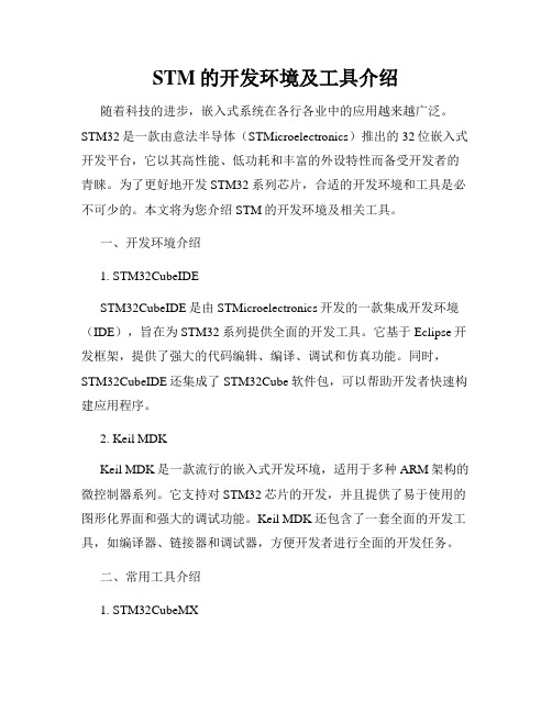
UM1025User manualGetting started with STM-STUDIOIntroductionSTM-STUDIO is a graphical user interface that allows sampling and visualizing in real timeof user's variables while the application is running. It is designed to run on PCs withMicrosoft® Windows operating systems.This tool works with STM8 microcontrollers through SWIM (single wire interface module)and with STM32 microcontrollers through JTAG or SWD (serial wire debug) interface.October 2013DocID18216 Rev 61/42Contents UM1025Contents1Installing STM-STUDIO . . . . . . . . . . . . . . . . . . . . . . . . . . . . . . . . . . . . . . . 51.1JRE installation . . . . . . . . . . . . . . . . . . . . . . . . . . . . . . . . . . . . . . . . . . . . . . 51.2STM-STUDIO installation . . . . . . . . . . . . . . . . . . . . . . . . . . . . . . . . . . . . . . 51.3Hardware support . . . . . . . . . . . . . . . . . . . . . . . . . . . . . . . . . . . . . . . . . . . . 52Running STM-STUDIO . . . . . . . . . . . . . . . . . . . . . . . . . . . . . . . . . . . . . . . 62.1Overview . . . . . . . . . . . . . . . . . . . . . . . . . . . . . . . . . . . . . . . . . . . . . . . . . . 62.2Creating variables . . . . . . . . . . . . . . . . . . . . . . . . . . . . . . . . . . . . . . . . . . . 62.2.1Adding absolute variables . . . . . . . . . . . . . . . . . . . . . . . . . . . . . . . . . . . . 72.2.2Adding expression variables . . . . . . . . . . . . . . . . . . . . . . . . . . . . . . . . . 112.2.3Adding statistical variables . . . . . . . . . . . . . . . . . . . . . . . . . . . . . . . . . . 122.2.4Adding plugin variables . . . . . . . . . . . . . . . . . . . . . . . . . . . . . . . . . . . . . 122.3Inspecting variables . . . . . . . . . . . . . . . . . . . . . . . . . . . . . . . . . . . . . . . . . 132.3.1Adding a variable viewer . . . . . . . . . . . . . . . . . . . . . . . . . . . . . . . . . . . . 132.3.2Customizing variable viewers . . . . . . . . . . . . . . . . . . . . . . . . . . . . . . . . 142.3.3Adding variables to a variable viewer . . . . . . . . . . . . . . . . . . . . . . . . . . 182.3.4Synchronizing viewers . . . . . . . . . . . . . . . . . . . . . . . . . . . . . . . . . . . . . . 192.3.5Hiding viewers . . . . . . . . . . . . . . . . . . . . . . . . . . . . . . . . . . . . . . . . . . . . 192.4Using the Point Viewer . . . . . . . . . . . . . . . . . . . . . . . . . . . . . . . . . . . . . . . 202.4.1Customizing Point Viewer . . . . . . . . . . . . . . . . . . . . . . . . . . . . . . . . . . . 202.4.2Adding a new point . . . . . . . . . . . . . . . . . . . . . . . . . . . . . . . . . . . . . . . . 212.4.3Customizing a point . . . . . . . . . . . . . . . . . . . . . . . . . . . . . . . . . . . . . . . . 222.5Configuring the acquisition settings . . . . . . . . . . . . . . . . . . . . . . . . . . . . . 232.5.1Replay from file mode . . . . . . . . . . . . . . . . . . . . . . . . . . . . . . . . . . . . . . 232.5.2Get data from target mode . . . . . . . . . . . . . . . . . . . . . . . . . . . . . . . . . . . 242.5.3Trigger configuration . . . . . . . . . . . . . . . . . . . . . . . . . . . . . . . . . . . . . . . 262.6Project and configurations . . . . . . . . . . . . . . . . . . . . . . . . . . . . . . . . . . . . 282.7Running a visualization session . . . . . . . . . . . . . . . . . . . . . . . . . . . . . . . . 312.7.1Starting a session . . . . . . . . . . . . . . . . . . . . . . . . . . . . . . . . . . . . . . . . . 312.7.2Variable visualization . . . . . . . . . . . . . . . . . . . . . . . . . . . . . . . . . . . . . . . 322.7.3Writing variables on the fly . . . . . . . . . . . . . . . . . . . . . . . . . . . . . . . . . . . 342.7.4Post-visualization analysis . . . . . . . . . . . . . . . . . . . . . . . . . . . . . . . . . . . 36 2/42DocID18216 Rev 6UM1025Contents Appendix A Syntax for expression variables. . . . . . . . . . . . . . . . . . . . . . . . . . . . 38 Revision history . . . . . . . . . . . . . . . . . . . . . . . . . . . . . . . . . . . . . . . . . . . . . . . . . . . . 40DocID18216 Rev 63/42List of figures UM1025 List of figuresFigure 1.Java Platform . . . . . . . . . . . . . . . . . . . . . . . . . . . . . . . . . . . . . . . . . . . . . . . . . . . . . . . . . . . . 5 Figure 2.STM-STUDIO initial screen . . . . . . . . . . . . . . . . . . . . . . . . . . . . . . . . . . . . . . . . . . . . . . . . . 6 Figure 3.Adding absolute variable directly from table. . . . . . . . . . . . . . . . . . . . . . . . . . . . . . . . . . . . . 7 Figure 4.Importing absolute variables. . . . . . . . . . . . . . . . . . . . . . . . . . . . . . . . . . . . . . . . . . . . . . . . . 9 Figure 5.Direct acquisition mode . . . . . . . . . . . . . . . . . . . . . . . . . . . . . . . . . . . . . . . . . . . . . . . . . . . 10 Figure 6.Snapshot acquisition mode. . . . . . . . . . . . . . . . . . . . . . . . . . . . . . . . . . . . . . . . . . . . . . . . . 10 Figure 7.Contextual menu to add expression variable . . . . . . . . . . . . . . . . . . . . . . . . . . . . . . . . . . . 11 Figure 8.Adding statistical variables. . . . . . . . . . . . . . . . . . . . . . . . . . . . . . . . . . . . . . . . . . . . . . . . . 12 Figure 9.SNR plugin configuration . . . . . . . . . . . . . . . . . . . . . . . . . . . . . . . . . . . . . . . . . . . . . . . . . . 13 Figure 10.Creating a variable viewer . . . . . . . . . . . . . . . . . . . . . . . . . . . . . . . . . . . . . . . . . . . . . . . . . 14 Figure 11.Customizing variable viewers. . . . . . . . . . . . . . . . . . . . . . . . . . . . . . . . . . . . . . . . . . . . . . . 15 Figure 12.Viewers settings . . . . . . . . . . . . . . . . . . . . . . . . . . . . . . . . . . . . . . . . . . . . . . . . . . . . . . . . . 16 Figure 13.Multiple viewers . . . . . . . . . . . . . . . . . . . . . . . . . . . . . . . . . . . . . . . . . . . . . . . . . . . . . . . . . 17 Figure 14.Adding variables to a variable viewer. . . . . . . . . . . . . . . . . . . . . . . . . . . . . . . . . . . . . . . . . 18 Figure 15.Synchronizing viewers . . . . . . . . . . . . . . . . . . . . . . . . . . . . . . . . . . . . . . . . . . . . . . . . . . . . 19 Figure 16.Hiding viewers . . . . . . . . . . . . . . . . . . . . . . . . . . . . . . . . . . . . . . . . . . . . . . . . . . . . . . . . . . 19 Figure 17.Point Viewer . . . . . . . . . . . . . . . . . . . . . . . . . . . . . . . . . . . . . . . . . . . . . . . . . . . . . . . . . . . . 20 Figure 18.Point settings . . . . . . . . . . . . . . . . . . . . . . . . . . . . . . . . . . . . . . . . . . . . . . . . . . . . . . . . . . . 20 Figure 19.Adding a point. . . . . . . . . . . . . . . . . . . . . . . . . . . . . . . . . . . . . . . . . . . . . . . . . . . . . . . . . . . 21 Figure 20.Customizing point settings . . . . . . . . . . . . . . . . . . . . . . . . . . . . . . . . . . . . . . . . . . . . . . . . . 22 Figure 21.Acquisition settings dialog box . . . . . . . . . . . . . . . . . . . . . . . . . . . . . . . . . . . . . . . . . . . . . . 23 Figure 22.Trigger parameters. . . . . . . . . . . . . . . . . . . . . . . . . . . . . . . . . . . . . . . . . . . . . . . . . . . . . . . 26 Figure 23.Workspace panel . . . . . . . . . . . . . . . . . . . . . . . . . . . . . . . . . . . . . . . . . . . . . . . . . . . . . . . . 28 Figure 24.Configuration operations in File menu . . . . . . . . . . . . . . . . . . . . . . . . . . . . . . . . . . . . . . . . 29 Figure 25.Selecting hardware and protocol . . . . . . . . . . . . . . . . . . . . . . . . . . . . . . . . . . . . . . . . . . . . 31 Figure 26.Start menu . . . . . . . . . . . . . . . . . . . . . . . . . . . . . . . . . . . . . . . . . . . . . . . . . . . . . . . . . . . . . 31 Figure 27.Variable visualization . . . . . . . . . . . . . . . . . . . . . . . . . . . . . . . . . . . . . . . . . . . . . . . . . . . . . 32 Figure 28.Visualizing different viewers. . . . . . . . . . . . . . . . . . . . . . . . . . . . . . . . . . . . . . . . . . . . . . . . 32 Figure 29.Showing all viewers . . . . . . . . . . . . . . . . . . . . . . . . . . . . . . . . . . . . . . . . . . . . . . . . . . . . . . 33 Figure 30.Adding a write variable. . . . . . . . . . . . . . . . . . . . . . . . . . . . . . . . . . . . . . . . . . . . . . . . . . . . 34 Figure 31.Writing on the fly. . . . . . . . . . . . . . . . . . . . . . . . . . . . . . . . . . . . . . . . . . . . . . . . . . . . . . . . . 35 Figure 32.Editing a value from the Read Value column . . . . . . . . . . . . . . . . . . . . . . . . . . . . . . . . . . . 35 Figure 33.Stop menu . . . . . . . . . . . . . . . . . . . . . . . . . . . . . . . . . . . . . . . . . . . . . . . . . . . . . . . . . . . . . 36 Figure 34.Replaying variable viewer visualization . . . . . . . . . . . . . . . . . . . . . . . . . . . . . . . . . . . . . . . 36 Figure 35.Showing indexes checkbox . . . . . . . . . . . . . . . . . . . . . . . . . . . . . . . . . . . . . . . . . . . . . . . . 36 Figure 36.Showing annotations . . . . . . . . . . . . . . . . . . . . . . . . . . . . . . . . . . . . . . . . . . . . . . . . . . . . . 37 4/42DocID18216 Rev 6DocID18216 Rev 65/42UM1025Installing STM-STUDIO 1 Installing STM-STUDIO1.1 JRE installationEnsure that the Java Run Time Environment (JRE) is installed on your machine. JREversion 1.7 or more recent is recommended (JRE 7).To check the installed JRE version, check that Java bin path is already added to PATHenvironment variable, then open a Windows command dialog and enter java -version.If you have a JRE version older than 1.7, please download the latest JRE version from/technetwork/java/javase/downloads/index.html.STM-STUDIO requires the 32-bit version of the JRE to be installed, even on 64-bit versions of Windows.Figure 1. Java Platform1.2 STM-STUDIO installationOnce the JRE is installed or updated, run STMStudio_setup.exe.1.3 Hardware supportSTM-STUDIO supports ST-LINK hardware with JTAG, SWD and SWIM protocols. STM-STUDIO also supports RLink (in-circuit debugger and programmer from Raisonance whichsupports JTAG, ICC and SWIM interfaces), STice advanced emulation system, and ST-TSLink as additional hardware targets.Running STM-STUDIO UM10256/42DocID18216 Rev 62 Running STM-STUDIO2.1 OverviewRun STMStudio.exe through the Desktop icon or the Program Folder shortcut that arecreated during the installation setup. The screen shown in Figure 2 appears.•The configuration panes display current settings which change according to the type of display selected.•The display area provides a visualization of the various settings currently selected.Figure 2. STM-STUDIO initial screen2.2 Creating variablesIt is necessary to create a list of variables to be inspected during the recording session.STM-STUDIO manages four kinds of variables:•Absolute variables that are identified by their physical storage address.•Statistical variables that can compute values like min, max, average and standard deviation of absolute variables.•Expression variables that are the result of a mathematical expression evaluation. An expression is the combination of absolute or statistical variables and mathematicaloperators (+,-,*, /…), for example: (Variable1+Variable2)*Variable3. Note thatexpression variables are evaluated after statistical variables, thus it is not possible tocompute statistics on expressions.•Plugin variables that contain user-configurable information.DocID18216 Rev 67/42UM1025Running STM-STUDIO2.2.1 Adding absolute variablesAbsolute variables are displayed in the upper pane of the Variables Settings pane. Theycan either be added directly, or be imported from an executable (.elf file).DirectlyVariables can be added directly from the table using the New contextual menu (right click onthe mouse). The new variable is added with default parameters. It is the user’s responsibilityto define the name, the address, the size or optionally the color of the variable by editingeach of the table fields.Figure 3. Adding absolute variable directly from tableRunning STM-STUDIO UM1025ImportedVariables can be imported from an application executable using File>Import variables:1.Select the file that contains the variables.a) Select whether to Store executable path relatively to the user settings file.Choose this to adapt the STMStudio user settings file to the directory tree policy,which is preferable when copying the project from one PC to another one, storingthe path relatively allows the copied project to open without having to browse forthe new application location.If the application remains at a fixed location, an absolute path is preferable. Notethat if the STMStudio settings file and application file are not stored on the samedisk, the path is necessarily stored in absolute.b) Select whether to Import scaled variables in expression:It is possible to import variables directly as scaled expressions, instead ofimporting variables then creating expressions. In this case, the 'A' and 'B'coefficients of the linear expression must be specified before importing. Severalvariables can be imported with the same coefficients.If one or both coefficients may change during the project lifetime, it isrecommended to first create constant expressions, before importing scaledvariables, and use these constant expressions as 'A' and 'B' coefficients. Thisallows future changes to the 'A' and 'B' values without modifying the scaledexpressions.c) Select the Show symbols containing ... and Match case to filter the symbolsdisplayed in the edit box.d) Click on the column header to sort the list by column if desired.e) Use multiple selection mode if desired:–shift+click for range selection,–ctrl+click for single item addition,–shift+ctrl+click for range addition.2. Select the variables.3. Click the Import button.The address, size and name parameters are provided by the executable debug information. 8/42DocID18216 Rev 6DocID18216 Rev 69/42UM1025Running STM-STUDIOFigure 4. Importing absolute variablesRunning STM-STUDIO UM102510/42DocID18216 Rev 6Acquisition modeAbsolute variables may be acquired in 2 modes:•Direct acquisition mode, which is not application intrusive, but does not give an instantaneous view of the application state.•Snapshot acquisition mode, which gives an accurate view of the application state, but which requires application instrumentation. Refer to the Section2.5: Configuring the acquisition settings for configuring this mode.Click on the icon on the left column in order to toggle the acquisition mode of a variable.Figure 5. Direct acquisition modeFigure 6. Snapshot acquisition modeDocID18216 Rev 611/422.2.2 Adding expression variablesExpression variables are displayed in the second leftmost pane in the Variables settingspane. Use the New contextual menu to add a new variable. For details on the allowedexpression syntax, please refer to Appendix A: Syntax for expression variables on page 38.Clicking on theExpression column will open the expression editor window, which will assistyou writing the expression (providing the list of known symbols and functions).Expressions can use application variables or statistic variables. They can also be constant (depending on no application or statistic variable). In the general case the result of anexpression cannot be re-used in another expression; only constant expressions can bereused in other expressions.Figure 7. Contextual menu to add expression variable2.2.3 Adding statistical variablesStatistical variables are displayed in the second lowest pane of the Variables settingspane. Use the New contextual menu to add a new variable. Then select the absolutevariable and the function to be computed. The scope defines the temporal window of thecomputing: on all records acquired since the acquisition start, or only on the last ones(number to be specified).Figure 8. Adding statistical variables2.2.4 Adding plugin variablesPlugin variables are defined in an external java plugin. An example is provided with sourceand java documentation for Signal/Noise Ratio computation. Refer to the"plugins/SnrPlugin/javadoc" subdirectory of STMStudio application for details of how toimplement your own plugin.12/42DocID18216 Rev 6Use the New contextual menu to add a new variable. Then select in the list of availableplugins ("Snr" is the first one available). A configuration window for the correspondingvariable will open (see example in Figure9 for the SNR plugin).In the case of the SNR plugin, select the variable on which the computation should bemade, and select the "touch" and "untouch" thresholds. Please refer to the plugin javadoc orjava source files for details on the SNR computation.Figure 9. SNR plugin configurationvariables2.3 InspectingOnce variables are created, they can be inserted in appropriate windows called “variableviewers” so that they can be visualized during a session. When creating a newconfiguration, one default variable viewer is created but the user can add as many variableviewers as necessary.2.3.1 Adding a variable viewerIn the Viewers settings pane, select the General tab and click on the Add Viewer button;or use the contextual menu within the Viewers settings pane and select the New VarViewer item.A new tab (VarViewer2) is added to the Viewers settings pane and a VarViewer2 windowis displayed in the display area.DocID18216 Rev 613/42Figure 10. Creating a variable viewerSettings paneEach time a new viewer is created, a new tab is added to the Viewers settings controlpane.2.3.2 Customizing variable viewersThe General tab in the Viewers settings pane contains settings that apply to all variableviewers.14/42DocID18216 Rev 6Figure 11. Customizing variable viewers•The format of all viewers: (Curve, Bar Graph or Table) can be changed here in a single action. This will override the local setting of each viewer, that may be changed afterwards.•Show Indexes: show a slider for all variable viewers to display the time in ms.•Add Viewer: create a new variable viewer.Each viewer supports custom settings that can be modified: select the corresponding tab and change the settings.DocID18216 Rev 615/42Figure 12. Viewers settingsFrom the Viewers settings pane, you can:•add a New Var Viewer, Rename the viewer, make the viewer Visible or Delete the selected viewer: use the contextual menu;•select the viewer display format: Curve, Bar Graph or Table;•select the variable display format: decimal or hexadecimal;•remove a variable from the viewer: select the variable in the list and click Delete;•clear the list of variables: press the Delete All button;•change the vertical axis range of values: set lower Value and upper Value. Each viewer is associated to a specific range of values. If a variable is outside that range ofvalues, the variable is not displayed. In this situation, it is useful to modify the verticalrange to make the variable appear.Note:At least one variable viewer must be defined. Therefore, the Delete Viewer menu is displayed only if there are at least two variable viewers.16/42DocID18216 Rev 6The viewers can placed either on the right side of the STMStudio main window, or in a second display. If several viewers are displayed in one area:•their size can be adjusted by a drag-and-drop action on the horizontal boundary,•their position can be changed by a drag-and-drop action, initiated out of the display area of the viewer (where such action is associated with the zoom).It's only possible to drag from an area with several viewers. It is possible to drop to any area (main window or second screen), irrespective of the drag area.Figure 13. Multiple viewersDocID18216 Rev 617/4218/42DocID18216 Rev 62.3.3 Adding variables to a variable viewerThere are two solutions:•Drag item from a table of variables and drop it directly either on the variable viewer display or in the list of variables located in the Viewers settings pane.•Use the Send Tocontextual menu in the Display Variables settings table.You can use multiple selections in each of the three variable tables to add several variablesat a time in a variable viewer.Figure 14. Adding variables to a variable viewerDocID18216 Rev 619/422.3.4 Synchronizing viewersViewers can be synchronized together by selecting All viewers Synchronized : scrollinghorizontally in a viewer also affects the other viewers.Figure 15. Synchronizing viewers2.3.5 Hidingviewers By default, all viewers are visible after creation. It is possible to temporarily hide a viewer (inorder to optimize the displayed area) without loosing its configuration: use the contextualmenu from the corresponding viewer tab.Figure 16. Hiding viewers2.4 Using the Point ViewerThe Point Viewer is created by default in addition to the default variable viewer. The PointViewer is unique and displays points, not variables. A point is an association of twovariables resulting in a screen coordinate: a variable on the X axis and a variable on the YaxisBy default, the Point Viewer is not displayed. To display it, proceed as for the variableviewers: check the Point Viewer item in the Views menu or the Visible contextual menu inthe Viewers settings pane.Figure 17. Point Viewer2.4.1 Customizing Point ViewerFigure 18. Point settingsUse the General tab in the Viewers settings pane to modify Point Viewer parameters.For both axes, the user can specify the attempted range of values.Caution:If the value of the Variable is outside the range of values currently defined for the axis, the point does not appear in the Point Viewer area.The user can also control the Draw Line: when checked, this option draws a curve using allpoint positions. By default (Draw Line not checked), the points are displayed as screenpoints.20/42DocID18216 Rev 6DocID18216 Rev 621/422.4.2 Adding a new pointTo create a new point, select the Point Viewer tab in the Viewers settings pane, displaythe contextual menu in the List of Points table and clickNew . A new point is added to thelist and to the Point Viewer legend.Figure 19. Adding a pointThe new point has a default name and color, no variable on X and Y (as shown by the redcrossed icon visible on Figure 19). It can then be customized.22/42DocID18216 Rev 62.4.3 Customizing a pointThe point name and color can be modified directly in the list by clicking on the Name fieldand on the Color chooser button.Annotations and variables on X and Y axes can be modified in the Update Point(s) panecombo boxes. Click on a point in the list to display the settings for that point; anymodification is then registered for the point.Note:The Point Viewer can display only variables that are acquired in the same mode.Select Show Annotations to display the annotations for the specific point.Point customizing is mandatory for points newly created, but can be done at any time forexisting points either directly in the list for the name and the color or by selecting the point inthe list and modifying the combo boxes or the check box.Note:When a point has no variable defined on X (or on Y), a red-crossed icon is added to the list(see Figure 20). This is the case after creating a new point, but also after deleting a variable that was referenced by the point. When you select an invalid point, the icon also appears inthe Update Point(s) pane near the combo box that should be filled. You must then updatethe point, otherwise it is not displayed during the next visualization session.Figure 20. Customizing point settingsDocID18216 Rev 623/422.5 Configuring the acquisition settingsSTM-STUDIO can run in two different modes:•Replay from file •Get data from target (Direct or Snapshot acquisition, as defined at the variable's level)Depending on the selected mode, some other parameters may need to be configured. Theacquisition settings are configured through the Option > Acquisition Settings menu.Figure 21. Acquisition settings dialog box2.5.1 Replay from file modeIn this mode, data is read from the specified file and no communication with the target isrequired. The display is not real time: the Graphical refresh rate defines the time lapsebetween records read from the file, independently from their timestamp saved during theacquisition. Specify the minimum value for the fastest possible replay, or a greater value fora slower replay. For a correct behavior, it is recommended to replay a file in the sameconfiguration as the one used during the acquisition of the data into that file.The mandatory conditions are:•Log raw data parameter must not be changed between the acquisition and the replay.•All absolute variables required by the graphical interface during the replay must be present in the log file.•Append mode option must be disabled when saving acquired data into the file.2.5.2 Get data from target modeVariable monitoring may be achieved in two different ways, according to the variableconfiguration:•Direct acquisition mode - The PC continuously reads data from the connected target.The maximum record size is six frames of 255bytes. The acquisition is not intrusive forthe application, except that the SWIM, JTAG or SWD pins must be reserved for the tool(moreover, on STM8, STM-STUDIO activates the SWIM, which impacts the STM8behavior after a reset: it remains stalled by the debug module). However, time elapsesbetween the reading of the first variable of a record and the reading of the last one.This can sometimes give a wrong image of the application state. For word variables, itcan even lead to unexpected values because MSB and LSB are not read exactly at thesame time.•Snapshot acquisition mode - The application must be instrumented so that variables are sampled on particular application events (user-defined). C source code and projecttemplates are provided in the “softTrace” subdirectory. Simply add DataAcq.h andDataAcq.c files into your project, and call the DumpTrace function where you expect tosample your application state. You may then customize as needed:–The maximum number of variables in one record (SNP_TRC_NB_MAX_WORD_ VAR in dataAcq.h): include a safety margin to avoid having to rebuild yourapplication each time you want to trace one more variable. STM-STUDIOcomputes the actual record size when the acquisition session starts. That numberonly affects the size of the trace header. STM-STUDIO displays an error messageif you try to trace more variables than the application allows.–The size of the trace buffer (SNP_TRC_BUFFER_SIZE): this size does not have to be a multiple of SNP_TRC_NB_MAX_WORD_VAR, but it must be able tocontain at least two records. A wide buffer is preferred in order to avoid bufferoverflow, all the more if your application calls “DumpTrace” frequently.For correct synchronization with records acquired in direct mode, a timebase must bedefined, reflecting the exact time period between 2 consecutive calls to DumpTrace: this isthe aim of SNP_TRC_TIMESTAMP_BASE_UNIT and SNP_TRC_TIMESTAMP_VALUEdefinition in dataAcq.c.Some parameters can be adjusted for data acquisition from target:•Graphical refresh rate: number of milliseconds between two graphical refreshes. The actual refresh rate depends on computer configuration, system and executionenvironment (the specified value is used for a system timer). Note that the graphicalrefresh process runs both concurrently and independently from the acquisition process(the acquisition is in general much faster than the graphical refresh rate).•Acquisition rate: defines the rate at which the host PC reads the target data. When set to the maximum, the acquisition process is a sequential loop limited by the CPUresources given to him by the Operating System. For long acquisition sessions spyingslowly changing variables, it might be better to reduce the acquisition rate, thus freeinghost CPU resources for other tasks, and also decreasing the log file size (if activated).•Under-sample data for graphical display: in this mode, the acquisition process continues even if the records put at graphical's disposal are still not consumed(displayed). As a result, when the graphical display is slower than the acquisition, someacquired records won't be displayed (but will however be logged to the file if thefunction is enabled, thus may be displayed later in “replay from file” mode). Conversely,24/42DocID18216 Rev 6。