圣劳伦斯散热器升级标配自动放气阀
佛罗伦萨散热器排气的方法

天气开始慢慢的降温了,许多朋友在安装结束或第二年运行打开暖气片之后,房屋里很久也没有暖和起来,这种情况大多数是因为暖气片内部积聚了大量的空气,产生“气堵”现象,阻碍系统管道中水流动,导热暖气片出现不热或发热不均的现象,这时我们就需要排气了,但是你知道正确的排气方法吗?现在我们以壁挂炉为例来描述。
1.打开锅炉,进行补水,压力表压力应达到1.5bar以上,并开启锅炉正常运行,因为在排气的过程中,锅炉的水泵可以排掉一部分气体。
2.用六角扳手关闭其中的一组散热器的回水阀门。
3.按图示方法用排气钥匙或一字螺丝刀逆时针拧开手动放气阀,为避免暖气片内部积气带出水流,可用抹布或干毛巾遮住气孔,在排气时应轻轻敲打散热器,保证内部所有气体排出。
4.当该组散热器排气结束后,将进水阀门关掉。
5.按照上述方法依此对每组散热器排气,在排气的过程中,如果锅炉停止运行,这时需要对锅炉进行补水以保证锅炉处于开启运行状态。
6.在最后一组散热器排气时,不要关闭回水阀门,直接排气即可。
7.最后再将所有的散热器进回水阀门都打开,排气过程结束。
EXTROL LBC系列水热膨胀吸收器(ASME)安装与运行说明书,模型35-LBC至600-LBC

Models 35-LBC through 600-LBCPartial Acceptance Bladder ModelsTHE MANUAL MAY RESULT IN SERIOUS OR FATAL INJURY AND/OR PROPERTY DAMAGE, AND WILL VOID THE PRODUCT WARRANTY. THIS PRODUCT MUST BE INSTALLED BY A LICENCED PROFESSIONAL. FOLLOW ALL APPLICABLE LOCAL AND STATE CODES AND REGULATIONS, IN THE ABSENCE OF SUCH CODES, FOLLOW THE CURRENT EDITIONS OF THE NATIONAL PLUMBING CODE AND NATIONAL ELECTRIC CODE,WORKING PRESSURE.A relief designated in the Product Manual, whichever is less. Do not expose Product to freezing temperatures or temperatures in excess of 240° F.Do not adjust the pre-charge or re-pressure this Product except for anyadjustments required at the time of initial installation, especially if Product corroded, damaged or with diminished integrity. Adjustments to pre-charge must be done at ambient temperature only. Failure to properly size the Product or follow these instructions may result in excessive strain on the system lead to Product failure, serious or fatalpersonal injury, leakage and/or property damage.oxygenated water which will cause internal corrosion and premature Product failure. Use a Therm-X-Trol ® for potable water systems and a Radiant Extrol ® for radiant heating systems. Mount vertically only. Donot install on dead-end pipe.For more information go to .NOTE: Inspect for shipping damage and notify freight carrier or store where purchased immediately if damage is present. To avoid risk of personal injury and property damage, if the product appears to be malfunctioning or shows signs of corrosion, call a licensed professional immediately. Current copies of the Product manual can be viewed at . Use proper safety equipment when installing.THIS IS THE SAFETY ALERT SYMBOL. IT IS USED TO ALERT YOU TO POTENTIAL PERSONAL INJURY AND OTHER HAZARDS. OBEY ALL SAFETY MESSAGES THAT FOLLOW THIS SYMBOL TO REDUCE THE RISK OF PERSONAL INJURY AS WELL AS PROPERTY DAMAGE.Failure to followleaking or flooding and/or property damage.® Expansion Tanksproperty damage. To minimize risk, a licensed professional must install and periodically inspect and service the Product. A drip pan connected to an adequate drain must be installed if leaking or flooding could cause property damage. Do not locate in an area where leaking could cause property damage to the area adjacent to the appliance or to lower floors of the structure.The AMTROL expansion tank may be placed in any convenient position within the mechanical room (or building). If multiple tanks are installed, they should all be on the same level.Point of ConnectionUnlike a conventional tank, the EXTROL sealed air cushion does not require replenishment so DO NOT connect to an air separator or other air collection device.As with any expansion tank, it is recommended that the EXTROL be connected to the suction side of the pump. This will prevent the pump head from becoming subtractive which may result in entry of air and vapor formation at high points in the system.By connecting the EXTROL on the boiler return, displacement of coolest system water into tank is ensured reducing energy waste.Low pressure drop components such as air separators and boilers may be placed between point of connection and pump suction if desired. System design will dictate the feasibility of this.Natural convection losses and the entry of air into tanks are eliminatedby connection to the side or underside of main pipe. The piping should be pitched up and away from the EXTROL to eliminate any potential air traps.connection on tank.2. Remove the plug or pipe cap from the system connection.3. Remove the 1 1/2” NPT plug covering the air charge valve.4. Before making any connection to the tank, check the tank and air charge (use an accurate pressure gauge). The air pressure must be equal to the minimum system pressure at the tank location.5. After making sure the air charge is correct, replace the valve cap and the 1 1/2” plug over the air valve.6. The EXTROL may now be piped to the system (use the suggested EXTROL piping diagrams on the next page).7. Using the table below, select appropriate pipe size. Connection to each EXTROL must have a lock shield gate valve and union to allow isolation and removal if required. Make up and fill valves, whether manual or automatic, should be tied into the connecting line. This will ensure that pump operation will not affect valve operation.Operational LimitsMaximum Operating Pressure: As stamped on nameplate Maximum Operating Temperature: 240 °FMinimum Operating Temperature: 35°F (non-glycol application)If unit is being installed in a glycol system where minimum temperatures fall below 35°F, contact the AMTROL technical service department at (401) 535-1216.Operating Instructions1. Check the expansion tank pre-charge before the system is filled with water. The charge is 12 psig unless noted otherwise on the tank label. Check to make sure this is the correct pre-charge pressure specified for the system.2. If the tank pre-charge pressure needs to be changed on a dry system follow the following procedure:a. Check the expansion tank air pressures at the pre-chargeconnection with an accurate tire type pressure gauge. The pre-charge connection is the same kind of connection found on automobile tires.b. If the pressure is low, charge the tank with nitrogen gas or withoil free compressed air. Check the pressure frequently during this process as you would when filling a tire with air.3. If, after the system has been filled with water and operating, it is found that the expansion tank pre-charge must be changed, use the following procedure:a. Turn off the heat source and allow the system water to cool toambient temperature.b. Close the lock-shield valve in the tank-to-system piping.c. Open the drain valve to empty the water from the tank.d. Check the tank air pressure at the pre-charge connection with anaccurate tire type air gauge. e. Refer to 2b above.f. Close the drain valve, open the lock-shield valve and turn on theheat source.g. Relock the lock-shield valve.PLEASE READ THE FOLLOWING INSTRUCTIONS CAREFULLYIMPORTANT GENERAL SAFETY INFORMATION -ADDITIONAL SPECIFIC SAFETY ALERTS APPEAR IN THE FOLLOWING INSTRUCTIONS.Firing Rate Length of Pipe Connectingof Boiler Tank to System:MBTU/H Below 11' 11' – 30' 31' – 100'2,000 1/2" 3/4" 1" 4,000 3/4" 1" 11/4" 8,000 1" 11/4" 11/2" 12,000 11/4" 1 1/2" 2" 16,000 11/4" 2" 21/2" 20,00011/2" 2" 21/2"WarrantyLBC Series Models: One (1) Year Limited Warranty Visit for complete warranty details.Suggested Piping Diagram© 2019 Worthington Industries Inc.Part #: 9017-095 (06/19)One or more features of this product are covered by U.S. patents, visit /patents for more information.1400 Division Road, West Warwick, RI USA 02893T: 800.426.8765。
暖气自动排气阀的型号结构原理及作用
暖气自动排气阀的型号:意大利OR公司暖气自动排气阀主要有2种型号:0500.015和0502..015,0502.016,0502.020。
0500.015暖气自动排气阀其排气口位于阀体上部侧面,4分口径,排气量最大40标准升每分钟。
0502.系列暖气自动排气阀其排气口位于阀体顶部,排气量最大70标准升每分钟。
其中0502.015口径为4分。
0502.016口径为4分,其与.0502.015的唯一区别是其外面镀了一层镍。
0502.020口径为6分。
暖气排气阀暖气自动排气阀作用:暖气自动排气阀,中国销量第一,浮筒式,口径DN15-DN20,耐温110℃,黄铜阀体,广泛用于分水器、暖气片、地板采暖,释放供热系统和供水管道中产生的气穴,暖气自动排气阀更适合应用在气候环境恶劣的北方地区,质量可靠,性能稳定,一年免费更换,杜绝国产品牌排气又排水的情况产生。
选择暖气自动排气阀就是选择品质!0502暖气排气阀暖气自动排气阀的技术参数:最大工作压力:10bar 最高工作温度:110℃连接方式:外螺纹口径:1/2″-3/4″0500暖气排气阀暖气自动排气阀的技术参数:最大工作压力:10bar最高工作温度:110℃连接方式:外螺纹口径:1/2″暖气排气阀暖气自动排气阀结构:阀体:黄铜阀杆:黄铜浮筒:PP暖气排气阀暖气自动排气阀价格:0500.015 53一个0502.015 58一个0502.016 65一个0502.020 65一个OR暖气排气阀暖气自动排气阀安装:1.排气阀必须垂直安装,必须保证阀体内浮筒处于竖直状态,不能水平或倒立安装;2.由于气体密度比水小,会沿着管道一直爬到系统最高点并聚集在此,为了提高排气效率,排气阀一般都安装在系统的最高点;3.为了便于检修,排气阀一般跟隔断阀一起使用,这样拆卸排气阀是不需要关停系统;4.排气阀安装好后必须拧松黑色的防尘帽才能排气,但不能完全取掉,万一发生排气阀漏水,可拧紧防尘帽。
斯派莎克:换热机组

QH3S
400kW ~ 1000kW
FT - 浮球疏水阀
FT - 浮球疏水阀
QuickHeat – 标准产品范围
冷凝水侧控制
型号 功率范围 管路布置 控制阀型式 PN - 电动 EL - 气动 PN - 电动 EL - 气动 PN - 电动 EL - 气动 PN - 电动 EL - 气动
QH2C
50kW ~ 300kW
蒸汽-热水系统
控制柜
变频器
蒸汽
二次侧供水
二次侧回水 冷凝水 定压膨胀装置
Easiheat 基本单元
循环回水泵 补水
采暖/空调热水机组
补水泵
蒸汽-热水系统
控制柜 变频器
生活热水供水 蒸汽
缓冲罐 (可选)
自来水供水 供水泵
Easiheat 基本单元
生活热水回水
生活热水机组
axsarocomaxsarocomquiheat换热机组基于最新一代的vahterus板壳式换热器50kw至10000kw最高可承受32barg压力的饱和蒸汽蒸汽疏水阀或自动疏水阀泵aptaxsarocomaxsarocomquiheat电动或气动控制阀精确匹配的蒸汽控制系统换热效率高的紧凑型板壳式换热器模块化设计结构紧凑坚固可选冷凝水排除方式axsarocomaxsarocomqui标准产品范围蒸汽侧控制型号功率范围管路布置控制阀型式冷凝水排除方式qh2s100kw标准fr快速反应pn电动el气动ft浮球疏水阀apt自动疏水阀泵qh3s400kw标准fr快速反应pn电动el气动ft浮球疏水阀apthc自动疏水阀泵qh4s1000kw标准pn电动el气动ft浮球疏水阀fr快速反应pn电动qh5s4000kw标准pn电动el气动ft浮球疏水阀fr快速反应pnaxsarocomaxsarocomqui标准产品范围冷凝水侧控制型号功率范围管路布置控制阀型式qh2c50kw标准pn电动el气动qh3c300kw标准pn电动el气动qh4c1300kw标准pn电动el气动qh5c3300kw标准pn电动elaxsarocomaxsarocomquiheatvseasiheateasiheatquickheat设计换热量范围最佳工况185kw1200kw100kw10000kw蒸汽侧控制50kw5000kw冷凝水侧控制换热器板式换热器ts6mvahteruspshe板壳式换热器最大连续工作压力epdm垫片26bargheatseal垫片52barg16barg最大连续工作温度epdm垫片140cheatseal垫片160c400caxsarocomaxsarocom定制非标换热机组axsarocomaxsarocomeasiheat基本单元冷凝水蒸汽控制柜循环回水泵二次侧回水补水泵补水定压膨胀装置二次侧供水变频器蒸汽热水系统采暖空调热水机组axsarocomaxsarocom缓冲罐可选蒸汽生活热水供水自来水供水生活热水回水easiheat基本单元控制柜变频器供水泵循环回水泵生活热水机组蒸汽热水系统
快速排气阀使用方法
快速排气阀使用方法
嘿,朋友们!今天咱来聊聊快速排气阀这个小家伙的使用方法。
你看啊,这快速排气阀就像是一个小魔术道具,能在关键时刻给你来个惊喜!它虽然个头不大,作用可不小呢。
使用快速排气阀,第一步,你得先找到它的安装位置,这就好比你要去一个陌生的地方,得先搞清楚路线不是?把它安在合适的地方,才能让它发挥出最大的功效呀。
然后呢,要检查一下它的各个部件是不是都完好无损,这就跟咱出门前得检查下钥匙、手机有没有带一样重要。
要是有个小零件松了或者坏了,那可就麻烦啦!
当一切准备就绪,就可以开始使用啦!想象一下,气体在管道里呼呼地跑,这时候快速排气阀就像个聪明的守门员,迅速地把多余的气体给放出去。
它工作起来可麻利啦!你要是操作得当,那气体排得又快又顺畅,就像夏天喝了一口冰凉的汽水,那叫一个爽!可要是你不小心弄错了步骤,哎呀,那可能就会有点小状况哦。
比如说,你安装得不够牢固,说不定在排气的过程中就会松动,这多闹心呀!或者你没注意到管道里还有其他的杂质,结果把排气阀给堵住了,那不就糟糕啦!
所以呀,使用快速排气阀可得细心细心再细心。
别小看它,它虽然不声不响的,但在关键时刻能帮上大忙呢!
你想想,要是没有它,那些气体憋在管道里出不来,那会是什么后果?就像人憋了一口气出不来一样难受呀!
总之呢,快速排气阀就是我们的好帮手,只要我们正确地使用它,它就能为我们的工作和生活带来便利。
大家可一定要记住这些使用方法哦,让这个小家伙发挥出它最大的作用!别不当回事儿,不然等出了问题可就后悔莫及啦!。
Vacmaster 14 加仑多用途干燥 湿洁风扬器操作手册说明书
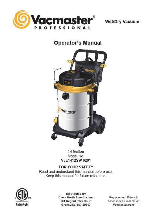
Distributed ByCleva North America, Inc.601 Regent Park Court Replacement Filters &Accessories available at:FOR YOUR SAFETY Read and understand this manual before use.Keep this manual for future reference.14 Gallon Model No. VJE1412SW 0201Operator’s Manual Wet/Dry VacuumWe take pride in producing a high quality, durable product. This Vacmaster ® product carries a limited five (5) year warranty against defects in workmanship and materials from date of purchase under normal household use. If product is to be used for commercial, industrial, or rental use, a 90 day limited warranty will apply. Please keep your receipt as proof of purchase. This warranty gives you specific legal rights, and you may have other rights, which vary from state to state. For product service call Customer Service at 1-866-384-8432.Not Covered by Warranty: • Any part that has become inoperative due to misuse, negligence, direct/indirect abuse, accidents, improper maintenance, repairs, or alterations;• Consumables such as filters and accessories;• Normal wear and tear of parts and attachments, such as hose, nozzles, or casters;• Normal deterioration of the exterior finish due to use or exposure;• Any product where serial number/data label is tampered with or removed;• Any product purchased from an unauthorized retailer.Warranty (2)Safety Instructions & Warnings (3)Double Insulation Instructions (4)Extension Cords (4)Unpacking & Checking Carton Contents (5)General Assembly Instructions (6)Dry Vacuum Operation (7)Liquid Vacuum Operation (8)Blower Operation (9)Maintenance (10)Installing & Cleaning Cartridge Filter (11)Installing & Cleaning Foam Wet Filter (12)Troubleshooting (12)Exploded View (13)Parts List ........................................................................................................................................14SECTION PAGEThank you for purchasing this Vacmaster ® wet/dry vacuum cleaner. Feel confident that with Vacmaster ® you are obtaining a high quality product engineered for optimal performance. This vacuum is capable of picking up liquids and dry materials.FOR YOUR SAFETY: CAREFULLY READ AND UNDERSTAND ALL INSTRUCTIONS.IMPORTANT SAFETY INSTRUCTIONS SAVE THIS MANUAL WARNING: FOR FUTURE REFERENCE.TO REDUCE THE RISK OF FIRE, ELECTRIC SHOCK, OR INJURY:READ AND UNDERSTAND ALL INSTRUCTIONS BEFORE USING THIS VACUUM. Read and understand this operator's manual and all labels on the Wet/Dry Vacuum cleaner before operating. Safety is a combination of common sense, staying alert, and knowing how your vacuum works. Use this Wet/Dry Vac only as described in this manual. To reduce the risk of personal injury or damage to your Wet/Dry Vac, use only Vacmaster ® recommended accessories.When using an electrical appliance, basic precautions should always be followed including the following:• Do not run vac unattended.• Do not vacuum, or use this Wet/Dry Vac near flammable liquids, gases, or explosive vapors like gasoline or other fuels, lighter fluids, cleaners, oil-based paints, natural gas, hydrogen, or explosive dusts like coal dust, magnesium dust, grain dust, or gun powder. Sparks inside the motor can ignite flammable vapors or dust.• Do not vacuum anything that is burning or smoking, such as cigarettes, matches, or hot ashes.• Keep cord away from heated surfaces.• Do not expose to rain. Store indoors.• Do not unplug by pulling on cord. To unplug, grasp the plug, not the cord.• Do not use with damaged cord, plug, or other parts.• If appliance is not working as it should, has been dropped, damaged, left outdoors, or dropped into water, return it to a service center.• Do not pull or carry by cord, use cord as handle, close a door on cord, or pull cord around sharp edges or corners.• Do not run Wet/Dry Vac over cord.• Do not handle plug or the Wet/Dry Vac with wet hands.• To reduce the risk of health hazards from vapors or dusts, do not vacuum toxic materials.• Do not use or store near hazardous materials.• Do not use this Wet/Dry Vac with a torn filter or without the filter installed except when vacuuming liquids as described in the operation section of this manual.• Do not allow to be used as a toy. Close attention is necessary when used by or near children.• To reduce the risk of injury from accidental starting, unplug power cord before changing or cleaning filter.• Do not leave Wet/Dry Vac unattended when plugged in. Unplug from outlet when not in use and before servicing. • Turn off Wet/Dry Vac before unplugging.• Do not put any object into ventilation openings. Do not vacuum with any ventilation openings blocked; keep free of dust, lint, hair, or anything that may reduce air flow.• Keep hair, loose clothing, fingers, and all parts of body away from openings and moving parts.• To reduce the risk of falls, use extra care when cleaning on stairs.• Unplug before connecting hose.• Use only as described in this manual. Use only manufacturer’s recommended attachments.• This appliance is provided with double insulation. Use only identical replacement parts. See “DOUBLE INSULATION INSTRUCTIONS”.When using as blower:• Direct air discharge only at work area. • Do not use Wet/Dry Vac as a sprayer.• Do not direct air at bystanders.• Keep children away when blowing.• Use safety goggles.Household TypeEXTENSION CORDSThis Wet/Dry Vac is double-insulated, eliminating the need for a separate grounding system. Use only identical replacement parts. Read the instructions for Servicing Double-Insulated Wet/Dry Vacs before servicing. Use this Wet/Dry Vac as described in this manual. Observe the following warnings that appear on the motor housing of your Wet/Dry Vac.When using an extension cord with your Wet/Dry Vac refer to the following table to determine the required A.W.G. wire size. Before using the cleaner make sure the power cord and extension cord are in good working condition. Make repairs or replacements before using the vacuum cleaner. Only use extension cords that are rated for outdoor use.• To reduce the risk of electric shock, unplug before cleaning or servicing.• DO NOT use without filters in place.CAUTION: Do not vacuum drywall dust, fireplace soot, or ash with a standard Wet/Dry filter. This is a very fine dust which will not be captured by the filter and may cause damage to the motor.When vacuuming fine dust, use a fine dust filter (included). To purchase the additional fine dust filters, call 1-866-384-8432 or get them at your local or online Vacmaster ® retailer.CAUTION: TO REDUCE THE RISK OF INJURY FROM MOVING PARTS, UNPLUG BEFORE SERVICING.DOUBLE INSULATED - GROUNDING NOT REQUIRED - WHEN SERVICING USE ONLY IDENTICAL REPLACEMENT PARTS.WARNING: TO REDUCE THE RISK OF ELECTRIC SHOCK, DO NOT EXPOSE TO RAIN. STORE INDOORS.Length of Extension Cord A.W.G. Wire Size Not recommended25 Feet 7.5 Meters50 Feet 15.25 Meters 100 Feet 30.5 Meters 150 Feet 45.7 Meters 110V-120V Amps 0-67-1011-1213-161818161416161612161414141212Remove all contents from the box. Remove the power head and take out any contents inside the collection tank. Check each item against the carton contents list.Carton Contents List:NOTE: The hose and accessories for thisKey A B C D E F G H I J K L M N O P Q R S T Description.........................................Qty. Vac Assembly ........................................1 Hose .....................................................1 Extension Wands ...................................2 Floor/Brush Squeegee Nozzle ...............1 Crevice Tool ...........................................1 Utility N ozzle ..........................................1 Professional Floor Brush .......................1 Foam Wet Filter .....................................1 Cartridge Filter .......................................1 Hose Storage Rack ...............................2 Noise Diffuser ........................................1 Front Caster...........................................2 Washer ..................................................4 Rear Wheel............................................2 Hub Cap ................................................2 Wheel Axle.............................................1 ‘R’ (Lock Pin) .........................................2 Tool Storage Bag ...................................1 Static Discharge Chain ..........................1 Manual ...................................................1Push/Pull Handle Tool Storage BagHandleOn/Off Switch Cord Wrap HookVacuum Port AssemblyLocking CasterDrain PortHose StorageRackLatch AssemblyCollection TankVacuum BaseRear WheelAssemblyCasterWARNING: DO NOT PLUG POWER CORD INTO POWER OUTLET. MAKE SURE PLUG IS DISCONNECTED BEFORE ASSEMBLING THE WET/DRY VACUUM.1. Verify that the power cord is disconnected from the outlet. (Fig. 1)2. Undo the latches. (Fig. 2)3. Lift the power head off the collection tank. (Fig. 3)4. Remove the contents from inside the tank; make sure you have all contents as listed in thecarton contents list on page 5. (Fig. 4)5. Turn the collection tank upside down and insert the two casters into the sockets on the bottomof the base. Apply pressure until casters snap into place. (Fig. 5)6. Insert the wheel axle into the rear wheel housing on the vacuum base. Insert a washer ontothe axle followed by a rear wheel and insert another washer. Insert the locking pin into the hole on the end of the axle to lock the wheel. Snap the hub cap onto the wheel. Repeat the same steps at the other end of the axle. (Fig. 6)7. Position the hose storage rack as illustrated. Insert one side of the rack into the channel,making sure it is secured in place. Squeeze in the other end and insert it into thecorresponding channel, making sure it is secured. (Fig. 7)8. Insert the push/pull handle into the handle socket mounted on the tank body. Push down untilthe lock pin clicks in place. (Fig. 8)9. Your vacuum comes ready for dry vacuum cleaning. For filter installation instructions, seepage 11. Optional: For improved dust filtration, fit a dust collection bag onto the inlet port,NOISE DIFFUSERFor quiet operation, install the noise diffuser into the blower port by inserting the locking end of the diffuser into the blower port and turning clockwise to lock into place.POLARIZED PLUGTo reduce the risk of electrical shock, this appliance has a polarized plug (one blade wider than the other). This plug will fit in a polarized outlet only one way. If the plug does not fit fully in the outlet, reverse the plug. If it still does not fit, contact a qualified electrician to install the proper outlet. Do not change the plug in any way. Double insulation eliminates the need for the three wire grounded power cord and grounded power supply system.10. For wet vacuum cleaning, install the supplied foam wet filter. For filter installation instructionssee page 12. (Fig. 10)11. Place the power head back on the collection tank aligning the top section with the latches, andsnap into place. (Fig. 11 & 12)12. Insert the locking end of the hose into the vacuum port and turn to lock into place. (Fig. 13)13. Fit the required accessory onto the suction tube. (Fig. 14)Note that a static discharge chain is attached to the bottom of the tank. It is normal for this chain to drag on the ground. Operating the vacuum in dry conditions can build up static, and the chain helps dissipate any build-up by allowing it a path of least resistance to the ground.WARNING: BE SURE TO READ, UNDERSTAND, AND APPLY, INFORMATION ENTITLED ‘SAFETY INSTRUCTIONS & WARNINGS’. DO NOT VACUUM IN AREAS WITH FLAMMABLE GASES, VAPORS, OR EXPLOSIVE DUSTS IN THE AIR. FLAMMABLE GASES OR VAPORS INCLUDE BUT ARE NOT LIMITED TO: LIGHTER FLUID, SOLVENT TYPE CLEANERS, OIL-BASED PAINTS, GASOLINE, ALCOHOL, OR AEROSOL SPRAYS. EXPLOSIVE DUSTS INCLUDE BUT ARE NOT LIMITED TO: COAL, MAGNESIUM, GRAIN, OR GUN POWDER. TO REDUCE THE RISK OF HEALTH HAZARDS FROM VAPORS OR DUST, DO NOT VACUUM TOXIC MATERIALS.WARNING: DO NOT PLUG POWER CORD INTO POWER OUTLET. MAKE SURE PLUG IS DISCONNECTED BEFORE CHANGING THE FILTERS.DRY VACUUMINGCAUTION: Do not vacuum drywall dust, fireplace soot, or ash with a standard Wet/Dry filter. This is a very fine dust which will not be captured by the filter and may cause damage to the motor. When vacuuming fine dust, use a fine dust filter (included). To purchase the additional fine dust filters, call 1-866-384-8432 or get them at your local or online Vacmaster ® retailer.WARNING: BE SURE TO READ, UNDERSTAND, AND APPLY, INFORMATION ENTITLED ‘SAFETY INSTRUCTIONS & WARNINGS’. DO NOT VACUUM IN AREAS WITH FLAMMABLE GASES, VAPORS, OR EXPLOSIVE DUSTS IN THE AIR. FLAMMABLE GASES OR VAPORS INCLUDE BUT ARE NOT LIMITED TO: LIGHTER FLUID, SOLVENT TYPE CLEANERS, OIL-BASED PAINTS, GASOLINE, ALCOHOL, OR AEROSOL SPRAYS. EXPLOSIVE DUSTS INCLUDE BUT ARE NOT LIMITED TO: COAL, MAGNESIUM, GRAIN, OR GUN POWDER. TO REDUCE THE RISK OF HEALTH HAZARDS FROM VAPORS OR DUST, DO NOT VACUUM TOXIC MATERIALS.WARNING: DO NOT PLUG POWER CORD INTO POWER OUTLET. MAKE SURE PLUG IS DISCONNECTED BEFORE CHANGING THE FILTERS.LIQUID VACUUMING1. Verify that the power cord is disconnected from the outlet. (Fig. 1)2. In order to prepare your vacuum for dry vacuuming, verify that the cartridge filter is securely mounted. With the power head removed and in an upside down position, make sure the filter is pushed in until it stops against the power head and the retainer is installed. Your wet/dry vac comes with the cartridge filter pre-installed. For installation instructions see page 11. (Fig. 2)3. Place the power head back on the collection tank and secure it in place using the latches. (Fig. 3)4. Insert the locking end of the hose into the vacuum port and lock into place. Push the required attachment onto the free end of the hose or extension. (Fig. 4)5. Plug the power cord into the power outlet. (Fig. 5)6. Turn the motor on by flipping the switch to the 'I' ON position. (Fig. 6)7. Once you have finished vacuuming, flip the switch to the 'O' OFF position and unplug the power cord from the outlet. (Fig. 7)O = OFF I = ONDO NOT USE THE CARTRIDGE FILTER FOR LIQUID VACUUMING.DO NOT USE DUST BAG FOR LIQUID VACUUMING.1. Verify that the power cord is disconnected from the power outlet. Ensure that the tank is cleanand free of dust and dirt. (Fig. 1)2. Remove the cartridge filter and install the foam wet filter over the filter cage and place thepower head back on the collection tank. For filter installation instructions see page 13. (Fig. 2) DO NOT USE THE CARTRIDGE FILTER FOR LIQUID VACUUMING.OPERATING INSTRUCTIONS: WET VACUUMING3. Fit the desired nozzle to the vacuum hose. (Fig. 3)4. Ensure that the switch is in the 'O' OFF position before plugging the power cord into the poweroutlet. (Fig. 4)5. Turn the motor on by flipping the switch to the 'I' ON position. (Fig. 5)6. After use, flip the switch to the 'O' OFF position and unplug the power cord. Empty and dry thecollection tank. (Fig. 6)IMPORTANT! When vacuuming large quantities of liquids, do not immerse the nozzle completely in the liquid; leave a gap at the tip of the nozzle opening to allow air inflow. The machine is fitted with a float valve that stops the suction action when the collection tank reaches its maximum capacity. You will notice an increase in motor speed. When this happens, turn off the machine, disconnect from power supply, and drain the liquid into a suitable receptacle or drain. To continue vacuuming, refit the collection tank with the drain cap. After wet vacuuming, turn the machineoff and remove plug from power supply. Empty the collection tank, clean and dry the inside and outside before storage. REMEMBER! The foam filter must be removed after wet vacuuming and a cartridge filter must be installed before dry vacuuming again.This Wet/Dry Vac has blowing capabilities. To use the blower feature follow the instructions listed. WARNING: ALWAYS WEAR SAFETY GOGGLES COMPLYING WITH ANSI Z87.1 (OR IN CANADA, CSAZ94.3) BEFORE USING BLOWER.WARNING: KEEP BYSTANDERS CLEAR FROM BLOWING DEBRIS.WARNING: WEAR A DUST MASK IF BLOWING CREATES DUST THAT MIGHT BE INHALED.1. Verify that the power cord is disconnected from the outlet. (Fig. 1)2. Make sure the collection tank is empty before using as a blower.3. Remove hose from the vacuum port. Remove noise diffuser from blower port.4. Insert the larger end of the hose into the blower port on the back side of the power head. (Fig. 2)5. Fit the desired attachment to the hose. (Fig. 3)WARNING: ALWAYS DISCONNECT THE PLUG FROM THE POWER OUTLET BEFORE REMOVING THE POWER HEAD FROM COLLECTION TANK.2. Disconnect the hose from the vacuum. (Fig. 2)3. Undo the latches and remove the power head from the collection tank. (Fig. 3)4. Clear all dirt or debris from the collection tank and hose. (Fig. 4)5. Clean or replace the filters.6. Check the hose, attachments and the power cord to ensure that they have not been damaged.7. Place power head back on collection tank and secure latches.IMPORTANT! Clean or change the cartridge filter regularly for best performance. ALWAYS USE CARTRIDGE FILTER FOR DRY VACUUMING. If the machine is used without the cartridge filter, the motor will burn out and the warranty will be voided. Always keep spare filters on hand. NOTICE! The filters included are made of high quality materials designed to stop small dust particles. The cartridge filter should be used for dry pick-up only. A dry cartridge filter is necessary to pick up dust. If the cartridge filter is wet, it will clog quickly and be very difficult to clean. Handle the filter carefully when removing it for cleaning and replacing it. Check the filters for tears or small holes. A small hole can let dust pass through and out of the filter. Do not use a filter with holes ortears; replace it immediately.Emptying the Collection Tank6. Verify that the power switch is in the ‘O’ OFF position before plugging the power cord into the outlet. (Fig. 4 & 5)7. Before turning ON the vac, firmly hold the loose end of the hose. Turn the motor on by pressing the switch to the ‘I’ ON position. (Fig. 6)8. Once you have completed blowing, flip the power switch to the 'O' (OFF) position and unplug the power cord from the outlet. (Fig. 7)Installing Cartridge Filter1. Verify that the power cord is disconnected from the outlet. (Fig. 1)2. Remove power head and place in upside down position.3. Install the cartridge filter over the filter cage with the flat end of the filter towards the power head. Carefully push filter in until it stops against the power head. (Fig. 2 & 3)4. Place filter retainer on top of cartridge filter over the raised lip and tighten down by turning retainer clockwise; do not over-tighten. (Fig. 4 & 5) Removing and Cleaning Cartridge Filter1. Unlock and remove the filter retainer by turning retainer handle counter clockwise.2. Carefully hold and pull the cartridge filter up for removal. (Fig. 6)3. Clean the cartridge filter by gently tapping or brushing dirt off. Cleaning should not be done indoors in living areas. For optimal performance a new filter is recommended.4. Install cleaned or new filter as above in steps 2 and 3 of Installing Cartridge Filter.5. Wet filters should be removed and allowed to air dry for 24 hours before installing onto the filter cage.IMPORTANT! Clean or change the cartridge filter regularly for best performance.ALWAYS USE CARTRIDGE FILTER FOR DRY VACUUMING. If the machine is used without the cartridge filter, the motor will burn out and the warranty will be voided. Always keep spare filters on hand.WARNING: ALWAYS DISCONNECT THE PLUG FROM THE POWER OUTLET BEFORE REMOVING THE POWER HEAD FROM THE COLLECTION TANK.WARNING: TO REDUCE THE RISK OF ELECTRIC SHOCK, UNPLUG BEFORE TROUBLESHOOTING.SymptomPossible Causes Corrective ActionWet/Dry Vacuum will not operate.1) No power supply.1) Check power supply: cord,breakers, fuses.2) Faulty power cord.2) Check the power cord and repair or replace as necessary.3) Collection tank full.3) Empty collection tank.Dust comes out from motor cover.1) The cartridge filter is missing or damaged.1) Attach or replace cartridge filter.Reduced efficiency and motor/speed vibration.1) There is a blockage in thenozzle, hose, or the collectiontank inlet. The cartridge filter is clogged by fine dust.1) Check nozzle, hose andcollection tank in lets f orblockage. Take off the filterand clean it or install a newcartridge filter.Installing Foam Wet Filter1. Verify that the power cord is disconnected from the outlet. (Fig. 1)2. Remove power head and place in upside down position. Follow instructions to remove cartridge filter.3. Carefully slide foam wet filter down over the filter cage making sure the cage is completely covered. (Fig. 2 & 3)4. Place the power head onto the collection tank.Cleaning Foam Wet Filter1. With the removed power head in an upside down position, carefully remove foam wet filter. (Fig. 4)2. Use a mild soap and water solution to wash foam wet filter and rinse with clean water. (Fig. 5)3. Allow filter to air dry before installing and using again.Part Part Number Description Quantity 1Power Head Assembly1 2551006102Hose Storage Rack2 3551120118Filter Cage1 4551259109Push/Pull Handle Receiver2 5551178105Latch Assembly26Collection Tank1 7551016105Vacuum Port Assembly1 8551303103Drain Assembly1 9551152114Static Discharge Chain1 10551113107Vacuum Base1 11551061108Rear Wheel Assembly2 12551034112Wheel Axle1 135********Locking Caster Assembly1 14551044118Caster Assembly1 155********Push/Pull Handle Assembly1 15.1551303105Cord Wrap Hook Assembly2 16VCFF Cartridge Filter1 175********Cartridge Filter Retainer1 18V2FBS Floor/Brush Squeegee Nozzle1 19V2FB Professional Floor Brush1 20V2CT Crevice Tool1 21V2UN Utility Nozzle1 22551060104Hose1 23V2EW Extension Wands2 24551303106Tool Storage Bag1 25VFF51Foam Wet Filter1 26551002117Air/Noise Diffuser1。
Rinnai Avenger Capella Plus 不通风煤气对流加热器使用手册说明书
This appliance shall be installed in accordance with:• Manufacturer’s Installation Instructions • Current AS/NZS 3000 & AS/NZS 5601• Local Regulations and Municipal Building CodesThis appliance must be installed, serviced and repaired by an Authorised Person.Portable Unflued Gas Convection Heaters With Electric Boost Operation ManualTo Suit ModelsAvenger 25 Plus Capella 18 PlusN10378This page intentionally blank.TABLE OF CONTENTSABOUT YOUR NEW AVENGER/CAPELLA PLUS (2)CONTROL PANEL LAYOUT (3)REMOTE CONTROL (4)FEATURES (5)IMPORTANT POINTS (6)CUSTOMER OPERATING INSTRUCTIONS (11)HOW TO OPERATE THE HEATER (12)ADJUSTING TEMPERATURES (13)HEATER MODES & FUNCTIONS (14)SETTING HEATER MODES (15)SETTING CLOCK (16)PROGRAMMING THE ON/OFF TIMERS (17)OPERATING THE ON/OFF TIMERS (18)PRE-HEAT (18)OVERRIDE FUNCTION (19)USING THE REMOTE CONTROL (19)CHILD LOCK (20)SAFETY DEVICES (20)CARE OF HEATER (21)TROUBLE SHOOTING (22)ERROR CODES (23)SPECIFICATIONS (24)CONTACT INFORMATION (26)ABOUT YOUR NEW AVENGER/CAPELLA PLUSCONTROL PANEL LAYOUTREMOTE CONTROLPUSH BUTTON IGNITION Only one touch of the STANDBY/ON switch is requiredto operate the heater.CHILD LOCK When the Child Lock is activated all controls other thanthe STANDBY switch will be locked. Deactivating thelock releases the controls. If the lock is activated whenthe appliance is in STANDBY, all functions will belocked.MEMORY The micro-computer records selected presettemperatures, the times programmed into Timers as wellas operating the Economy/Auto-Off and Pre-heatmodes, to maintain comfort levels.PRE-HEAT This function will automatically operate the appliancebefore the programmed start time of the Timer, in orderto heat a room to the pre-set temperature by theprogrammed time.FILTER INDICATOR When the fan filters become covered with dust, the filterindicator will flash. The filters should be vacuumed atregular intervals to avoid unnecessary strain on theappliance.REMOTE CONTROL For the convenience of operating the heater betweenSTANDBY or ON, as well as adjusting the temperatureup or down while at a short distance from the heater.DUAL WEEKDAY / WEEKEND TIMER The Dual WEEKDAY/WEEKEND Timer allows you to program the appliance to come on for two separate periods each day, one period in the morning and one period in the evening, on separate WEEKDAY and WEEKEND timers. The built in Pre-heat Mode brings the room temperature to the temperature you have selected, by the time programmed into the Timer.The Dual Timer feature means that you can "Set and Forget" your heater. It will turn itself ON or to STANDBY at the times you have programmed until you cancel the Timer program.ECONOMY / AUTO-OFF FUNCTIONThe Economy / Auto-Off functions are energy saving feature designed to control the room temperature and are automatically selected in all modes. FEATURESCUSTOMER OPERATING INSTRUCTIONSHOW TO OPERATE THE HEATERADJUSTING TEMPERATURESHEATER MODES & FUNCTIONSYour appliance has several "MODE" settings to choose from. The factory default setting is "GAS". For your convenience in normal operation the appliance’s memory will select the “MODE” that was last used.COMFORT AND ECONOMYAs a room is warmed, the walls and ceilings are also warmed, making one feel a little warmer than when the ceilings and walls were cold, even though the room temperature is the same. The Economy (ECON) function prevents discomfort from overheating and saves energy.“GAS” MODEWhen operating in this mode, the appliance will heat the room using gas convection. Gas combustion in this mode is continuous and will adjust automatically to maintain the “SET” temperature."GAS ECON" MODEWhen operating in this mode, the appliance will heat the room using gas convection. Once the “SET” Temperature has been maintained for a period of 30 minutes, the comfort control system will progressively lower the “SET”temperature by 2°C over a period of 60 minutes. When ‘ECON’ only is selected, gas combustion is continuous and will adjust automatically to maintain the “SET” temperature minus 2°C.Note:that during operation in this mode the “CURR” room temperature displayed may be lower than the “SET”temperature, however this is normal."GAS ECON AUTO OFF" MODEWhen operating in this mode, the appliance will heat the room using gas convection. Once the “SET” temperature has been maintained for a period of 30 minutes, the comfort control system will progressively lower the “SET”temperature by 2°C over a period of 60 minutes. When ‘ECON’ & ‘AUTO OFF’ are selected, gas combustion will start and stop automatically to maintain the “SET” temperature minus 2°C.Note:that during operation in this mode the “CURR” room temperature displayed may be lower than the “SET”temperature, however this is normal.“GAS ELECTRIC” MODEWhen operating in this mode, the appliance will heat the room using Gas convection or Gas and Electric convection. Electric convection is used only when the room is cold and/or when the heat load is high. Gas combustion in this mode is continuous and will adjust automatically whilst the electric convection is turned on and off to maintain the “SET” temperature.“GAS ECON ELECTRIC” MODEWhen operating in this mode, the appliance will heat the room using Gas convection or Gas and Electric convection. Electric convection is used only when the room is cold and/or when the heat load is high. Once the “SET”temperature has been maintained for a period of 30 minutes, the comfort control system will progressively lower the “SET” temperature by 2°C over a period of 60 minutes. When ‘ECON’ only is selected, gas combustion is continuous and will adjust automatically to maintain the “SET” temperature minus 2°C.Note:that during operation in this mode the “CURR” room temperature displayed may be lower than the “SET”temperature, however this is normal.“GAS ECON ELECTRIC AUTO OFF” MODEWhen operating in this mode, the appliance will heat the room using Gas convection or Gas and Electric convection. Electric convection is used only when the room is cold and/or when the heat load is high. Once the “SET”temperature has been maintained for a period of 30 minutes, the comfort control system will progressively lower the “SET” temperature by 2°C over a period of 60 minutes. When ‘ECON’ & ‘AUTO OFF’ are selected, gas combustion will start and stop automatically to maintain the “SET” temperature minus 2°C.Note:that during operation in this mode the “CURR” room temperature displayed may be lower than the “SET”temperature, however this is normal.“ELECTRIC” MODEWhen operating in this mode, the appliance will heat the room using Electric convection. The Electric element will switch on and off automatically to maintain the “SET” temperature.Note:Electric convection will only operate when the “SET” temperate is at least 2°C higher than the “CURR”temperature. Timer operation is disabled when the appliance is in the “ELECTRIC” only mode.SETTING HEATER MODESSETTING CLOCKPROGRAMMING THE ON/OFF TIMERSOPERATING THE ON/OFF TIMERSPRE-HEATOVERRIDE FUNCTIONUSING THE REMOTE CONTROLCHILD LOCKSAFETY DEVICESOVER HEAT SWITCHWhen the heater gets too hot during operation (for example when the filters or air outlet louvers are blocked) this device turns the gas and or electric heating element off automatically. Remove cause of overheat (clean filters) allow heater to cool, then re-ignite.FUSEThe electrical circuits are protected by a fuse. When the fuse blows, the heater will not operate at all. The fuse must be replaced by an authorised person.FLAME FAILURE DEVICEThis device automatically cuts off the gas supply to the heater in the event of a gas failure. To restore the gas supply to the heater, turn it off, and then follow the ignition procedure.OXYGEN DEPLETION SAFETY DEVICEIf the oxygen level in the room drops below a pre-set limit, this device cuts the gas supply to the heater. If the oxygen depletion device operates, turn the heater off, ventilate the room, then follow the ignition procedure to re-light. Heater will not re-light unit room is fully ventilated.TILT SWITCHIf the heater is knocked over, the tilt switch will cut the gas supply and or the power to the electric heating element. The fan keeps running. To restore the gas supply, stand the heater upright, turn it off then follow the ignition procedure. The tilt switch may also operate if the heater is jolted or picked up whilst in operation.POWER FAILUREIn the event of a power failure or power cut, the gas valves will automatically close. After the power is re-instated the appliance must be operated manually.CARE OF HEATERTROUBLE SHOOTINGERROR CODESDIMENSIONSGENERAL SPECIFICATIONS Refer to appliance data plate for Gas Type, Gas Rates and Burner Pressures.General Description Portable Gas Convector Heaters Gas Control Electronic ControlBurnerSurface Combustion BurnerGas Connection 3/8” MI BSP into 1.5mflexible hose with bayonet connection Convection Fan Multi-Speed FanIgnition System Continuous Spark electronic Ignition Operation Push Button Electronic/Remote Control Safety DevicesOverheat Switch Electric FuseFlame Failure Sensor Oxygen Depletion Sensor Tilt SwitchPower Failure Sensor Electric BoosterAvenger 25 Plus - 2000 WCapella 18 Plus - 2000 WNOTE。
WAUKESHA天然气发动机
3.9空燃比
可燃混合气中空气质量与燃气
质量之比为空燃比。
空气质量
式中:α—空燃比
燃气质量
4四行程发动机工作原理
4.1进气行程
活塞在曲轴的带动下由上止点移至下止点。此时,进气门 开启,排气门关闭,曲轴转动180°。在活塞移动过程中, 汽缸容积逐渐增大,汽缸内气体压力逐渐降低,汽缸内形 成一定的真空度,空气和燃气的混合气通过进气门被吸入 汽缸,并在汽缸内进一步混合。
发动机主要由以下两大机构和几大系统组成,即由曲柄连 杆机构,配气机构、调速系统、空气和燃料供给系统、润 滑系统、冷却系统、点火系统和启动系统组成
1曲柄连杆机构
曲柄连杆机构是发动机实现工作循环,完成能量转换的主要 运动零件。它由机体组、活塞连杆组和曲轴飞轮组等组成。
2 配气机构
配气机构的功用是根据发动机的工作顺序和工作过程, 定时开启和关闭进气门和排气门,使可燃混合气或空气进 入气缸,并使废气从气缸内排出,实现换气过程。
4.2压缩行程
压缩行程时,进、排气门同时关闭。活塞从下止点向上止 点运动,曲轴转动180°。活塞上移时,工作容积逐渐缩 小,缸内混合气受压缩后压力和温度不断升高。
4.3作功行程
当活塞接近上止点时,由火花塞点燃混合气,混合气燃烧 释放出大量的热能,使汽缸内气体的压力和温度迅速提高。 高温高压的燃气推动活塞从上止点向下止点运动,并通过 曲柄连杆机构对外输出机械能。随着活塞下移,汽缸容积 增加,气体压力和温度逐渐下降。在做功行程,进气门、 排气门均关闭,曲轴转动180°。
涡流强度提高燃烧速度的原因:
1.缩短燃烧的滞燃期,使燃气与新鲜空气更快的混合; 2.提高火焰传播速度,涡流强度越大,火焰前锋的传播速
度越大,从而燃烧速度提高,热释放率增大。
- 1、下载文档前请自行甄别文档内容的完整性,平台不提供额外的编辑、内容补充、找答案等附加服务。
- 2、"仅部分预览"的文档,不可在线预览部分如存在完整性等问题,可反馈申请退款(可完整预览的文档不适用该条件!)。
- 3、如文档侵犯您的权益,请联系客服反馈,我们会尽快为您处理(人工客服工作时间:9:00-18:30)。
圣劳伦斯散热器升级标配自动放气阀
近日从圣劳伦斯传出消息,自2014年3月开始所有暖气片将标配自动放气阀,据悉,这在业内属独家。
放气阀是什么
放气阀也叫排气阀、放风阀,应用于包含独立采暖、集中供热、锅炉采暖、中央空调、地板采暖及太阳能采暖等各类采暖系统的管道排气。
排气阀有手动和自动之分,顾名思义,手动放气阀是通过手动开关,将空气排出采暖管道的阀门,自动放气阀是一种安装在供暖或供水系统上具有自动放气功能的阀门。
放气阀工作原理
采暖管道中,水中通常都溶有一定的空气,而且空气的溶解度随着温度的升高而减少,这样水在循环的过程中气体逐渐从水中分离出来,并逐渐聚在一起形成大的气泡甚至气柱,因为有水的补充,所以经常有气体产生。
这些气体的存在,一是容易和水产发生化学反应,生成碳酸,腐蚀暖气片内壁,甚至导致暖气片漏水;二来还会阻碍热水的运行,导致暖气片不热,影响散热效果,放气阀则是将这些气体及时排出管道,保证热能的传递,这和医护人员把输液管中的气体排出是一个道理。
手动放气阀是用户手动开关的阀门,不定时将气体排出;自动放气阀则主要是利用空气压力原理,安装在暖气系统后管道中的水会自动流入阀里,当管道没有空气时,阀门处于关闭状态,一旦进入空气,随着气体压力增大,阀芯出现自然收缩,空气就经过阀芯空隙排出管道,空气排空后阀芯空间又被水充满。
由于自动放气阀的阀芯结构特殊,只允许空气排出而不会排水,如此就达到了自动放气的目的。
自动放气阀优势有哪些
手动放气阀由于受人为限制,经常拧动容易松动,有水流噪音,且易漏水,操作费时费力,如果忘记放气,则容易影响散热效果,甚至暖气片使用寿命也会受到牵连。
而自动放气阀一改局面,将所有问题迎刃而解,更加适合现代生活的快节奏及优雅步调。
下面我们一起来认识一下自动放气阀,看看它如何升级散热器性能。
1.安装简便:自动放气阀安装十分简单,先检查暖气系统连接口是否有杂质,若有将其清除,然后拧紧自动放气阀手轮,将自动放气阀安装在暖气设备上,用六角扳手顺时针拧紧六角即可。
2.手自动合一:与手动放气阀不同,自动放气阀实现了全自动和手动二者合一,无需用户费心即能自动放气,若需快速排气只要旋开顶部手轮45度即开始排气,待空气排完就会有水流出,此时迅速将手轮旋回并拧紧。
3.漏水几率为零:自动放气阀质量稳定,材质耐高温,经久耐用,且内部设有止水阀,确保使用过程中绝不会发生漏水事故。
4.出气口位置任意:从保护周边物体安全的角度考虑,自动放气阀的排气口可自由设定,通过自由转动自动放气阀手轮来实现。
5.任意方向安装:与浮球式放气阀相比,现在新型的自动放气阀安装在暖气系统上,无需考虑安装方向,在任意方向都可正常使用。
6.安装自动放气阀后,暖气系统里不再有空气滞留,确保系统快速高效制热,不再发生暖气片不热、热能被浪费等现象。
以钢制暖气片为例,由于需满水保养,但是人们很难保证散热器内部无空气,达到真正的满水保养。
而自动放气阀能彻底的杜绝这些问题,无需人为操作就可自动排气,保证暖气系统运行畅通、制热效果优良,同时让系统里不再留得住空气,杜绝了空气对内部的腐蚀,从而延长了设备的使用寿命。
圣劳伦斯标配自动放气阀升级产品性能
自2014年3月开始,圣劳伦斯全线产品上升级为自动放气阀。
据了解,该阀为与业内一线生产企业联合独家定制,材质为优质环保黄铜,表面经高度抛光镀铬,外观精美,功能齐全,安装和使用方便,长期使用不会锈蚀,或影响系统工作甚至发生漏水。
专家称,自动放气阀也许很常见,但是标配自动放气阀,圣劳伦斯可谓是国内第一家,此举势必带动散热器行业的新变革。
(注:素材和资料部分来自网络,供参考。
请预览后才下载,期待你的好评与关注!)。