HighTek HK-7002-3-4串行口光电隔离器
ACPL-772L和ACPL-072L高速CMOS光电隔离器数据手册说明书

Data Sheet
Lead (Pb) Free RoHS 6 fully compliant
RoHS 6 fully compliant options available; -xxxE denotes a lead-free product
3.56 ± 0.13 (0.140 ± 0.005)
4.70 (0.185) MAX.
7.62 ± 0.25 (0.300 ± 0.010)
6.35 ± 0.25 (0.250 ± 0.010)
5˚ TYP.
0.254
+ 0.076 - 0.051
(0.010
+ 0.003) - 0.002)
1.080 ± 0.320 (0.043 ± 0.013)
LEAD COPLANARITY = 0.10 mm (0.004 INCHES).
NOTE: FLOATING LEAD PROTRUSION IS 0.25 mm (10 mils) MAX.
0.635 ± 0.25 (0.025 ± 0.010)
12 ˚ NOM.
ACPL-072L Small Outline SO-8 Package
Part number
ACPL-772L
ACPL-072L
Option
RoHS Compliant
Non RoHS Compliant
-000E
-
-300E
-
-500E
-
-020E
-
-320E
-
-520E
捷瑞2102G 无源光电隔离接口转换器使用说明说明书

JaRa® MODEL 2102GRS232<->RS485 无源光电隔离接口转换器使用说明概述:MODEL 2102G是RS-232与RS-485之间的防静电防浪涌双向接口转换器。
直接插在计算机串口上使用。
简单的两线通讯,可以架构RS485半双工点到点及点到多点通信网络。
在以下系统中有广泛的应用:◆工控自动化系统 ◆PLC和PLD ◆监视智能化系统◆POS刷卡机、收款机系统 ◆数据采集、控制系统等MODEL 2102G能够将RS-232串行口的TXD和RXD信号转换成两线平衡的半双工RS-485信号。
无需外接电源,可直接从RS232端口的3脚窃电,同时由7脚(请求发送RTS)、4脚(数据终端准备好DTR)给MODEL 2102G辅助供电,自动的流控使你不必重新设置硬件与安装软件,使用非常简单。
MODEL 2102G内部有光电隔离芯片,可消除因两端设备不稳定的电压引起的“地环流”,保护两端设备的串口不被“地环流”产生的大电流损坏!性能参数:串口界面 接口兼容EIA/TIA的RS232C、RS485标准传输介质 普通双绞线传输距离 1.2Km(可达到19.2 Kpbs)电源要求 串口供电/外部供电光电隔离 隔离电压连续2500V,瞬间7000V脉冲接头方式 DB9F、DB9M、DB9F(带四位接线端子)信号 RS-232: TxD, RxD, RTS, CTS, DTR, DSR, DCD, GNDRS-485:Date+/A,Date-/B, GND工作方式 异步半双工通信协议 透明工作温度 -10℃~70℃相对湿度 5%~95%连接器和信号:MODEL 2102G采用DB9F与RS232设备相连,另一端采用DB9M与RS485设备相连。
接口定义如下:RS232C引脚定义DB9F 1 2 3 4 5 6 7 8 RS232C DCD RXD TXD DTR GND DSR RTS CTSRS485引脚定义DB9M 1 2 3 4 5 6RS485 Date+/A Date-/B GND +5v 其工作电源获得有两种情况: 直接由RS232端口的3脚供电,同时7(RTS)、4(DTR)脚给MODEL 2102G辅助供电; 当RS232不能正常供电时,可由RS485端的DB9M 6脚(+5v)和5脚(GND)供电。
物理隔离器产品说明书

物理隔离器产品说明书物理隔离器产品说明书© Copyright. UD Technology Inc. 10/20/2002物理隔离器产品说明书本产品-物理隔离器是根据《电网和电厂计算机监控系统及调度数据网络安全防护规定》及相关文件中物理隔离器相关描述并基于技术实现等考虑针对电网安全应用设计的。
它位于实时电力调度数据网络和电力综合信息网络边缘,能够在物理层次上实现两个网络在任何时刻不相连,并且通过系统设置在数据进入实时调度网络前进行数据分析,防止威胁、破坏等敌意攻击。
在具体的应用环境中,将安全保护程度相对较高的网络称为内部网,将安全保护程度相对较低的网络称为外部网,与它们相连的控制、处理部分、接口等分别称为Internal System和External System,与它们直接相连的网络接口分别称为Internal Port和External Port,位于Internal System和External System之间为Switch System。
Internal System和External System、Internal Port和External Port在物理上任何时间不会连同。
该设备有三个物理独立的部分组成,一是Switch System,另两部分是分别是Internal System和External System。
具体系统逻辑结构见图:功能支持硬件功能物理隔离功能本产品处于两个既需要通信又有较高安全要求的网络交界处,无论是从OSI模型还是从TCP/IP协议栈来看,网络双方任何时刻在物理层上能够实现比特流的完全阻截和隔断。
数据交换功能数据交换是物理隔离器能够实现通信基础,它以信息数据的采集、存储、读取、删除的方式,完成Internal System和External System之间的信息交互。
通信的双方在通信过程中处于对等地位,即双方具有相同的协议栈,在数据交换过程中(通信)均可接收和发送数据。
CommScope 700 850 PCS-AWS WCS DC 四通道复用器说明书

Page of 14Quadplexer, 700/850/PCS-AWS/WCS,DC Manual SelectBTS-to-feeder and feeder-to-antenna application Convertible mounting bracketsOBSOLETEThis product was discontinued on: February 20, 2019Replaced By:CQX782123-DS-43E14F15P25Quadplexer, 700/850/PCS-AWS/WCS,DC Sense, 4.3-10Product ClassificationProduct TypeQuadplexerGeneral SpecificationsProduct Family CBC782123ColorGray Common Port Label COMMON Modularity 1-Single MountingPole | Wall Mounting Pipe Hardware Band clamps (2)RF Connector Interface7-16 DIN Female RF Connector Interface Body StyleLong neckDimensionsHeight 250 mm | 9.843 in Width 225 mm | 8.858 in Depth62 mm | 2.441 in Ground Screw Diameter 6 mm | 0.236 in Mounting Pipe Diameter Range40–160 mmPage of 24Outline DrawingElectrical SpecificationsImpedance50 ohmLicense Band, Band PassAWS 1700 | CEL 850 | LMR 750 | PCS 1900 | USA 700 | USA 750 | WCS 2300Electrical Specifications, dc Power/Alarmdc/AISG Pass-through Method User selectabledc/AISG Pass-through Path Manual adjustment sets dc/AISG path Lightning Surge Current5 kALightning Surge Current Waveform 8/20 waveformOperating Current at Voltage15 mA @ 12 V | 15 mA @ 24 V 7–30 VdcVoltage7–30 VdcElectrical Specifications, AISGAISG Carrier2176 KHz ± 100 ppmInsertion Loss, maximum 1 dBReturn Loss, minimum15 dBElectrical SpecificationsSub-module11111 Branch12334 Port Designation698–798824–894AWS-PCS PCS-AWS WCSLicense Band LMR 750, Band PassUSA 700, Band PassUSA 750, Band Pass CEL 850, Band Pass AWS 1700, BandPassPCS 1900, BandPassWCS 2300, BandPassElectrical Specifications, Band PassFrequency Range, MHz698–798824–8941695–17802110–21801850–19902305–2360Insertion Loss, typical, dB0.350.350.30.30.3Total Group Delay, maximum,ns5050303030Return Loss, minimum, dB2020202020Isolation, minimum, dB5050505050Input Power, RMS, maximum,W200200200200200Input Power, PEP, maximum,W200020002000200020003rd Order PIM, typical, dBc-155-155-155-1553rd Order PIM Test Method 2 x 20 W CW tones 2 x 20 W CW tones 1 x 20 W AWS CW tone1 x 20 W PCS CW tone2 x 20 W CW tonesHigher Order PIM, minimum,dBc-155Higher Order PIM Test Method 2 x 20 W CW tones Block DiagramPage of34Environmental SpecificationsOperating Temperature-40 °C to +65 °C (-40 °F to +149 °F)Ingress Protection Test Method IEC 60529:2001, IP67Packaging and WeightsIncluded Mounting hardwareWeight, net 5.9 kg | 13.007 lb44Page of。
CMOS封装设备简介

Copyright(c) 2012 All rights reserved by KST CO.,LTD.
KST CO.,LTD
1 A t Gl h & UV M/C 1.Auto Glass Att Attach
1-2 M/C Configuration (Top View)
3. HOUSING VISION Housing location Align Y-axis Moving 2. TRAY FEEDER Feeding Pin way of Ball Screw feeding type 4.PICK-UP HEAD X,Y,Z DIGITAL CONTRL
KST CO.,LTD
2 H i R t ti M/C 2.Housing Rotation
2-3 Specification
■ SYSTEM CONFIGURATION 1. 1 M/C PERFORMANCE - CAPACITY : 1times product quantity Min 5ea ~ Max 10ea (only UPH product (HOUSING) status, working conditions and other matters may vary by) 2 SYSTEM LAY OUT 구성 : MAGAZINE TO MAGAZINE STAND ALONE TYPE 2. 3. UTILITY - POWER : AC220V, 1Φ, 50/60Hz - AIR : 4∼6kg/㎠ - VACUUM : 500mmHg - (USER UTILITY apply) ■ APPLICATION 1. Apply to PACKAGE : CCD MODULE HOUSING - (USER refer to the provided drawing) 2. TRAY SIZE : 150mm(W)* 150mm(L) * 10mm(T) or (USER provide specification standards) 3 MAGAZINE : USER provide application spec (USER 사급품) 3.
2 路隔离语音控制器说明书 V1.1 (型号:YT-02)

2路隔离语音控制器说明书V1.1(型号:YT-02)秦皇岛千目电子有限公司电话:************传真:************/1.产品特性 (2)2.产品图片、接口介绍 (2)2.1产品外形和接口图片 (2)2.2接口介绍 (3)2.3产品尺寸图 (3)3.语音录制过程 (3)4.控制方式 (4)4.1接线方式 (4)4.2控制方式 (4)5.参数设置 (5)5.1硬件连接 (5)5.2软件录音 (5)5.2.1连接设备 (5)5.2.2录音 (5)5.3参数设置 (6)5.4放音测试 (6)6.技术支持及联系方式 (6)语音控制器说明书(型号:YT-02)YT-02语音模块是秦皇岛千目电子2015年全新工业级产品。
具有价格低、稳定可靠、可重复录音、开关触点控制、体积小等特点。
通过2组触点控制。
主要应用范围:安装工程、报警提示、产品扩展语音功能等。
1.产品特性●板载功放模块,最高可输出功率达3w,声音响亮。
●WA V音频格式,音频录制时间可达24分钟。
●语音内容可以通过TTL转换器进行跟换。
●板载音量调节,可根据实际安装需求进行调整。
●2组触点控制,可接入常开、常闭触点控制。
●板载Flash存储器,成本低、可靠性更好。
●性能参数工作电源电压:直流12-24V工作温度:-20~85℃音频输出功率:8欧3-5W2.产品图片、接口介绍2.1产品外形和接口图片2.2接口介绍◆电源接口:接线端子V+接直流电的正极;G接直流电的负极。
电压12-24V直流。
◆TTL下载口:连接到TTL转换器,信号对应R---T、T---R、G---G。
◆SPK:声音输出接口,直接接无源喇叭,播放语音。
◆OUT:3.5音频接口,可外接音箱、音柱等设备,进行语音播放。
◆输入1-2:为2路输入信号。
与V+短接就可以触发对应的语言播放。
◆JDQ继电器输出:没有语音播放时处于常闭状态,有语音播放时处于常开,2.3产品尺寸图标注单位:(毫米)长*宽*高:81.5*50*31.4(长度不包含两侧安装耳朵)3.语音录制过程通过“音频合成软件”把文字转换为WA V格式音频文件存储到电脑。
EOC-700型继电保护光纤通信接口装置

2EOC-700型继电保护光纤通信接口装置2.1装置概述EOC-700型继电保护光纤通信接口装置是用于各种线路保护中的光电转换设备,完成提供光纤接口的保护装置与数字通信设备(PCM、SDH微波/光纤等)的复接功能。
与数字通信设备复接的电接口特性符合CCITT制定的G.703接口协议标准,并提供2M电口和64K同向接口可选择。
EOC-700装置提供两路独立的光纤/电口通道,这两路通道由保护装置设定为单通道工作(另一停用)或一主一热备工作方式。
详细描述请参见《EOC-701继电保护光纤通信接口装置说明书》。
EOC-700装置可与深圳南瑞科技有限公司的PRS-753光纤分相纵差成套保护装置、PRS-701/702超高压线路成套保护装置等高压微机保护配合,传输三相电流和开关信号。
2.2装置特点1)数据的传输采用高效的同步通讯方式,采用先进、灵活的大规模可编程器件FPGA,提供了两路独立的全双工数据通道。
2)灵活的接口方式:2M电接口和64K同向数据接口方式可选,可以适应不同场合的应用。
3)装置内部采用适于光纤传输和E1传输的编解码方式,提高了数据传输的可靠性,抗干扰能力强。
4)采用全数字锁相环技术,提高了时钟的稳定性。
2.3技术参数1)光纤接口a)线路码速率:2MHzb)线路码型:CMIc)光接头:SC/PCd)光模块收发模式:模式—— 单模波长—— 1310nme)发送功率:≥-9dBmf)接收灵敏度:≤-40dBm2)电接口:电接口特性符合CCITT制定的G.703接口协议。
3)直流电源输入电压: 48V;允许偏差:±20%4)环境温度:正常工作温度:-5 ~ 40 ℃极限工作温度:-10 ~ 55 ℃贮存及运输:-25 ~ 70 ℃5)绝缘耐压及抗干扰性能:符合GB/T14598的规定。
2.4工作原理2.4.1装置原理及构成EOC-700装置的任务是为保护装置和数字通信设备提供一条透明的传输通道,即将保护装置发送的光信号转换为电信号通过数字通信设备传输到线路对端,同时将从数字通信设备接收来的电信号转换成光信号后发送给保护装置,其原理框图如图2-4-1所示。
洁诚电子 70C1080H01 电源保护设备升级套件用户指南说明书
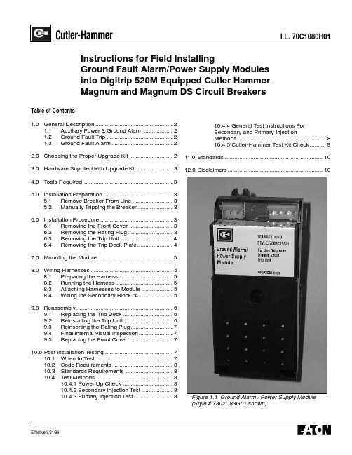
I.L. 70C1080H01Figure 1.1 Ground Alarm / Power Supply ModuleI.L. 70C1080H01Page 3 3.0 Hardware Supplied with Upgrade KitEach Cutler-Hammer Field Installable Kit for GroundAlarm / Power Supply module for Magnum DS Breakerwith Digitrip 520M comes with the following:a) This Instruction Leaflet - (#70C1080H01)b) Ground Alarm/Power Supply Module(#7802C83G01, G02 or #7802C82G01)c) A completed, four conductor wiring harness(#2C12797G05)d) Two #6, self-tapping 3/8” Phillips screws(#29286206)e) Five tie wraps - (#765A029H01)4.0 Tools Required (not supplied)Installation of the module requires:a) 10mm ratchet or socket driverb) 1/8" (3 mm) flat bladed screwdriverc) Medium Phillips screwdriverd) Wire cutters (for tie wraps)e) Amp pin insertion/extraction tool(AMP # 305183-R)(see note on Page 6)Page 5 I.L. 70C1080H01Next, loosen the two screws at the bottom of the steelTrip Deck Mounting Plate. Lift the plate upward thenswing it to the left to expose the cavity where the GroundAlarm / Power Supply Module will be mounted.7.0 MOUNTING THE MODULETake one of the supplied self tapping screws and partiallyscrew it into the bottom retaining boss for the module.The screw anchoring tabs for the module are slotted.Slide the bottom tab of the module behind the partiallyinserted screw. Take the second screw and place it in theother slotted notch on the top of the module and anchorthe unit in place in the breaker. Now go back and tightenthe bottom retaining screw and ascertain that the GroundAlarm / Power Supply Module is firmly seated in theMagnum frame.8.0 WIRING HARNESSESTwo wiring harnesses must be attached to the GroundAlarm / Power Supply Module. The first, a three conductorconnector, is already pre-wired into the breaker at the8.1 Preparing the HarnessUsing the supplied tie wraps, secure the four conductorharness into a tight and neat bundle. Cleanly trim theexcess tails from the tie wraps.Page 6I.L. 70C1080H01of the breaker (Figure 8.1). The wires are marked A-10,A-11, A-14 and A15. According to the label on the block,insert them into the proper terminal slots. This is done simply by pushing them in until they lock. After the audible “click, ” confirm that they are secure by slightly pulling on each wire.two lower partially loosened attachment screws. Tuck all wiring bundles neatly behind it. Position the mounting tabs of the Trip Indicator Assembly (also the Overcurrent Trip Switch / Bell Alarm if this option is attached) mounting tabs behind the steel Trip Unit Mounting Plate. (Fig. 9.1)Fig. 8.1 Wiring Secondary Block “A”Fig. 9.1 Proper Seating of Trip Indicator Assembly behind the steel Trip Unit Mounting Deck.Confirm that the steel control wire for the Trip Indicator Assembly is not bound nor its operation interfered with.(Fig. 9.2)Replace the two top screws that hold the steel Trip Unit Mounting Plate in place. Tighten all four appropriately and confirm that the trip deck plate is firmly seated.9.2 Reinstalling the Trip UnitAlign the Digitrip unit with the guide pin on the plate and spring clip of the Magnum Circuit Breaker. (see previous Fig. 6.3)Press the unit into the breaker until the pins engage into the connectors and the lower spring clip engages over the Digitrip’s housing.Page 7I.L. 70C1080H019.3 Reinserting the Rating PlugCarefully, insert the rating plug into the cavity on the right-hand side of the trip unit. Align the three pins on the plugwith the sockets in the cavity. The plug should fit with aslight insertion force. Use a 1/8" (3 mm) wide screwdriverto tighten the M4 screw and secure the plug and the tripunit to the circuit breaker (as removed in previous Fig.6.2). Close the rating plug door.CAUTIONDO NOT FORCE THE RATING PLUG INTO THECAVITY. FURTHERMORE, THE M4 SCREW SHOULDBE TIGHTENED ONLY UNTIL IT IS SNUG. DO NOTUSE A LARGE SCREWDRIVER. A 1/8" (3 MM) WIDESCREWDRIVER BLADE IS ADEQUATE.Fig. 9.2 The steel Control Wire of the Trip IndicatorAssembly9.4 Final Internal Visual InspectionBefore proceeding any further, do a visual inspection toinsure that none of the breaker’s internal wiring mighthamper any mechanical operation or compromise properfit of any component. Use any remaining tie wraps to tidyany wires which might be askew.9.5 Replacing the Front CoverPartially pull down the latching arm on the front of thebreaker and slide the breaker cover down into place ontothe frame. Using a 10mm ratchet or driver, tighten all fourretaining bolts in each corner of the cover. Make sure thatthe cover is squarely in place. Latch the breaker andreset the red flag on the Trip Indicator Assembly whichprotrudes from the front cover above the Trip Unit.Proceed with the test sequence.10.0 POST INSTALLATION TESTING10.1 When to TestTesting prior to start-up can best be accomplished withthe breaker out of its cell or in the Test, Disconnected, orWithdrawn (or Removed) cell positions.Page 8I.L. 70C1080H01 CAUTIONTESTING A CIRCUIT BREAKER WHILE IT IS IN-SERVICE AND CARRYING LOAD CURRENT IS NOTRECOMMENDED.TESTING OF A CIRCUIT BREAKER THAT RESULTS INTHE TRIPPING OF THE CIRCUIT BREAKER SHOULDBE DONE ONLY WITH THE CIRCUIT BREAKER INTHE TEST OR DISCONNECTED CELL POSITIONS ORWHILE THE CIRCUIT BREAKER IS ON A TESTBENCH.Page 10I.L. 70C1080H0112.0 DISCLAIMERSThis instruction booklet is published solely for information purposes and should not be considered all inclusive. If further information is required, consult Cutler-Hammer,Inc.The sale of the product shown in this literature is subject to the terms and conditions outlined in appropriateCutler-Hammer, Inc., selling policies or other contractual agreements between the parties. This literature is not intended to and does not enlarge or add to any such contract. The sole source governing the rights and remedies of any purchaser of this equipment is thecontract between the purchaser and Cutler-Hammer, Inc.NO WARRANTIES, EXPRESSED OR IMPLIED, IN-CLUDING WARRANTIES OF FITNESS FOR A PAR-TICULAR PURPOSE OR MERCHANTABILITY , OR WARRANTIES ARISING FROM THE COURSE OF DEALING OR USAGE OF TRADE, ARE MADE RE-GARDING THE INFORMATION, RECOMMENDA-TIONS, AND DESCRIPTIONS CONTAINED HEREIN.In no event will Cutler-Hammer, Inc., be responsible to the purchaser or user in contract, in tort (including negligence), strict liability, or otherwise for any special,indirect, incidental, or consequential damage or loss whatsoever, including, but not limited to, damage or loss of the use of equipment, plant or power system, cost of capital, loss of power, additional expenses in the use of existing power facilities, or claims against the purchaser or user by its customers resulting from the use of the information, recommendations, and descriptions con-tained herein.11.0 STANDARDSThe Cutler-Hammer, Inc. Digitrip Trip Units are listed by the Underwriters Laboratories, Inc.®, UL File E52096, for use in Magnum Circuit Breakers. These same units are also listed by the Canadian Standards Association (CSA)under file LR 43556.All Digitrip units have also passed the IEC 947-2 testprogram which includes radiated and conducted emission testing. As a result, all units carry the CE mark.CAUTIONBEFORE PLUGGING A TEST KIT INTO THE TEST PORT, PLACE THE LTM JUMPER IN THE INACTIVE POSITION (SEE FIGURE 4.3). AFTER TESTING,RETURN THE LTM JUMPER TO ITS ORIGINAL POSITION.。
- 1、下载文档前请自行甄别文档内容的完整性,平台不提供额外的编辑、内容补充、找答案等附加服务。
- 2、"仅部分预览"的文档,不可在线预览部分如存在完整性等问题,可反馈申请退款(可完整预览的文档不适用该条件!)。
- 3、如文档侵犯您的权益,请联系客服反馈,我们会尽快为您处理(人工客服工作时间:9:00-18:30)。
RS-232
串行口光电隔离器
HK-7002/7003/7004产品说明书
一、产品概述
二或连续重量:、性能参数
接口:符合和异步协议连接器:两侧都使用连接器传输模式:异步,全双工,全透明
隔离电压:脉冲电源:从端口供电(,或)EIARS-232CCITTV.24DB92500Vrms RS-232TXD RTS DTR 500VDC 30g
传输速率:外形尺寸:使用环境:℃到℃,相对湿度为到300BPS-57600BPS
63mmX33mmX17mm -40855%95%
四、连接器和信号
符合EIARS-232C、CCITTV.24的标准。
2、3脚是数据发送与接收:7、8引脚是RTS与CTS;4、1引脚是DTR和DCD;6引脚是DSR;5引脚是GND。
RS-232接口(TODTE):连接器:使用DB-25/9孔型连接器信号:内部信号线均是独立的。
1、型号选择
用户首先应该了解自己的RS-232系统使用了几条
信号线,然后选择适当的型号来保护自己的RS-232通信系统。
例如:对于DB9的传统2、3、5三线的终端,可以选择支持三线两路一收一发的隔离器HK-700X;对于2、3、4、5、7五线的终端,可以选用支持五线四路两收两发的隔离器如九线需全部隔离,则选择HK-7004;
1HK-700X RS-232RS-232TODTE TODCE PC DTE MODEM DCE DTE DCE RS-232DB252DTE 2DCE DTE RS-232HK-700X HK-700X TODTE TODCE UNIX RS-232MODEM 、连接方法
可以串接于原来系列的联接线和设备的接口之间,在任何一端均可,注意和的方向。
一般而言,、多用户属于设备,、终端属于设备、但也不一定。
真正判断设备是或设备,还应该从该设备的接口的信号线来入手。
如接口引脚发送输出的是;引脚接收输入的是。
所以,如果两个设备(如终端和多用户卡)使用交叉的电缆相联,在使用时,不论插在哪一侧,都应将的一侧接设备,将的一侧接电缆。
五、应用领域:等各种多用户系统保护种类多用户终端与主机
保护程控交换机、计费终端、话务台保护卫星接收机保护多用户卡
不共地的设备间的提款机保护、路由器
HK-700X HK-700XRS-232ISOLATORS RS-232RS-232RS-23290%RS-232A B RS-232A B 50V 80V RS-232RS-2322500Vrms 500VDC RS-232RS-232HK-700X RS-232UNIX ATM 串行口光电隔离器又称为串口隔离器(),它采用了先进的光电隔离技术,极大限度地保护了串行接口设备,避免了地线回路电压、浪涌、感应雷击、静电、热插拔等恶劣环境对设备的损坏。
接口的损坏是通信设备硬件的损坏,造成的原因以上是由于两端设备不共地、各类浪涌、感应雷击、静电干扰、热插拔,电磁干扰等恶劣环境对设备的损坏。
比如设备和设备使用接口相连,如果和之间的地线之间有大于的电压差(经常会达到以上),则通信就会不正常,接口可以随瞬间,连续的峰值电压差,还可以吸收静电和电磁干扰,保护设备的接口。
由于采用了光电隔离技术,完全隔离了两端设备的电气与地线回路,使得一侧的电信号变成光信号以后传到另一方,在变回到电信号,从而保护通信设备免受电源地线回路和浪涌的干扰和损坏,明显地提高了通信系统的可靠与稳定性。
产品已经被广泛应用于电力、保险、电信、银行、证券、程控等行业的点到点通信系统、多用户系统、监视控制系统、程控交换机计费终端、卫星接收机、自动提款机等领域。
有效铁路、邮局、金融、DTR GND
D S R RTS CTS RI
保护地
数据终端准备信号地数据装置准备请求发送清除发送响铃指示发送数据接收数据SOUT (TXD)SIN(RXD)三、连接器和信号:RS-232CDTE 端引脚分配
DB9(PIN)孔型123456789
RS-232C 接口信号
RS-232CDCE 端引脚分配
SIN(RXD)SOUT (TXD)DTR GND
D S R RTS CTS RI
保护地
接收数据发送数据数据终端准备信号地数据装置准备请求发送清除发送响铃指示DB9(PIN)针型123456789
RS-232C 接口信号
注:三线光电隔离转换器
五线光电隔离转换器
全线(九线)光电隔离转换器
HK-7002HK-7003HK-7004。