YOKOGAWA压力变送器介绍教学教材
横河川仪 EJA530A 压力变送器 规格书
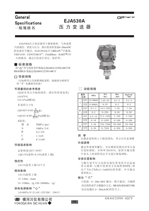
GS 01C21F01-02CY标准规格RE JA530A 压力变送器用于测量液体、气体或蒸汽的液位、密度与压力,然后将其转变成4~20mADC TM 的电流信号输出。
EJA530A 也可与BRAIN 手操器、TM YHC4150、CENTUMCS 、FieldMate 、HART 375互相通讯,通过它们进行设定、监控等。
ABCD可调量程的参考精度(包括从零点开始的线性、滞后性和重复性)若量程小于XX 取值:环境温度影响o 总影响量/28℃(50F )±[0.15%量程+0.15%量程上限]±0.1%量程上限/12个月稳定性±0.005%/V (21.6V~32V DC ,350Ω)供电电源影响“”功能规格MPaPsi (D1)Bar (/D3)2Kgf/cm (/D4)10~200kPa 调 零在膜盒量程的上下限范围内,零点可任意调整外部调零通过外部调零螺钉,可在测量范围内对零点进行连续调校,分辩率为0.01%,量程可通过数字表头上的量程设定开关进行现场调校。
安装位置影响与膜片面平行方向的安装位置变化不会造成零点漂移,与膜片面垂直方向旋转到90度,将会产生0.27kPa{1.1inH2O}的零漂,并可通过调零校正。
膜 盒A B C D XMP a {psi }40kPa {5.8}0.2{29}1{145}8{1160}振动影响±0.1%量程上限(5~15Hz ;4mm15~150Hz ;2g 150~2000Hz ;1g )0~200kPa量程范围量程范围量程范围量程范围量程/范围□ 1.45~290~2914.5~2900~29072.5~14500~1450720~72000~72000.1~20~21~200~205~1000~10050~5000~5000.1~20~21~200~205~1000~10050~5000~5000.1~20~20.5~100~105~500~50性能规格(以标准零点为基准调校量程,接液部分材质代码“S ”充灌液为硅油)输出“ ”2线制,4~20m A D C 输出,数字通讯,可编程设定线性或平方根输出方式,BRAIN 或HART FSK 协议加载在 4~20mA DC 的信号上。
压力变送器的参数设定PPT演示文稿

调用自检页
ESC
返回上一页
HOME
显示菜单页
NO
放弃设置,光标回到前面作标
OK
继续显示下一页
PARM
键入参数设置模式
SET
显示SET(设置)菜单
SLOT
返回监视页
UTIL
调用公共页
COPY
屏幕打印
12
F4
F2
F3
13
参数设置
• 在需要时,设置或改变参数值。完成后,
记住用“DIAG”键进行确认,
• ⑴位号设置(C10:TAG NO) • 在仪表出厂之前,TAG NO.在已按订货
• ※注意:零点调整时的数值变化大小与一字
螺丝刀的旋转速度有关。因此,精调时应 慢,粗调可加快。
• 注:当零点调校好,至少30秒后才能关掉
变送器电源。
24
谢谢大家!
25
变送器接线盒里用BT200挂钩连接,也可通 过中断端子板传输线连接。
• 2、在线通讯条件:
回路电阻=R+2RC=250~600Ω 回路电容=0.22μF(最大值)
4
BT200的操作方法
1、键面的排列
5
菜单页
页主题
信息
菜单选项 最多可显 示6项
参数页
参数项, 最多可 显示3 种参数
对应功能命令
6
2、操作键的功能 • ⑴ 数字/字母键和SHIFT键 • 利用数字/字母键直接输入数字,结合SHIFT键可以输入字母 • a:输入数字、符号和空格(0—9…)
17
• ⑶阻尼时间常数设定(C30:AMP DAMPING)
按两 次回 车键
用 ∧ 或 ∨ 选择出 “4.0sec”
压力变送器使用说明书
安装○普通型及小巧型变送器的安装①若压力系统有瞬间过压,该变送器过载范围满足系统要求,并配置缓冲阀;②测量介质应与变送器的结构材料相兼容;③测量介质不能堵塞变送器的引压孔;④禁止随意拆卸、碰撞变送器及强行绞拧导线,严禁用异物捅引压孔;⑤根据产品连续类型,查对现场接口是否与产品一致。
若为螺纹接口,应缓速拧紧,注意密封,不能把转矩直接加到变送器壳体上,只能加在压力接口的六角上。
○投入式变送器的安装●注意事项①安装地点的液体可能产生的静压力不能超过变送器的量程;②测量介质应与变送器的结构材料相兼容;③测量介质不能堵塞变送器的进液孔;④安装时要缓速放入或提出,严禁用强力拉扯电缆或用金属等硬物捅压膜片。
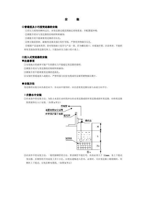
●安装方法变送器的安装方向为垂直向下,在动水中使用时,应注意使变送器压面与水流方向平行。
1在静水中安装①在水池中的安装方法:为防止水泵打水时的冲击抖动变送器或损坏变送器或损坏变送器,应将变送器原理液体出入口安装。
(如图a所示)②在深井中的安装方法:一般用插钢管的方法,要求钢管不能打弯,内劲必须大于35mm,易上下提动变动器,在钢管的不同高度上若干小孔,以便水通畅进入管内,必要时,可在变送器上缠烧钢丝,用钢丝上下提动,以免拉断电缆线。
(如图b所示)2在动水中安装在动水中安装时需加静水装置①方法之一:在水道中插入钢管,要求钢管壁稍厚一些,并在其上下不同高度若干个小孔,以阻尼水波和消除动水压力的影响。
(如图c所示)②方法之二:若为清水域的沙石水床,以浅埋为好。
(如图d所示)③方法之三:这种方法即能消除水流压力和波浪的影响又能起到过滤浊水泥沙的作用(如图e所示)○普通型及投入式变送器接线信号(电源)端子设置在电气盒的一个独立腔室内。
接线前,先拧下表盖,把信号(电源)线从穿线孔穿入,把线接在+、-端子及地上,拧紧表盖和穿线孔螺栓。
信号线不要与其它电源线一起穿金属管或放在同一线槽中,也不要再强电设备附近通过。
注意:接好线后,务必将表盖拧紧,以免潮气进入电气盒内,损坏电路。
横河压力变送器说明书的解读
横河压力变送器说明书的解读横河压力变送器是一种常用的工业自动化仪表设备,广泛应用于各种压力测量和控制领域。
本文将深入解读横河压力变送器的原理、结构和应用,以及其在工业生产中的重要作用。
一、横河压力变送器的原理横河压力变送器通过将压力信号转换为电信号来实现测量和控制。
其工作原理基于压阻效应,也就是当受力物体改变形状或体积时,导致电阻发生变化。
横河压力变送器中的压阻元件通常为硅片式压阻传感器,它能够根据受力物体施加的压力大小而改变阻值。
二、横河压力变送器的结构横河压力变送器的主要构成部分包括传感器元件、信号调理电路和输出模块。
传感器元件是测量中的关键部分,它采用硅片和膜片的结构,通过对硅片加工形成微小腔室,并在膜片上形成压阻电阻。
当受力物体施加压力时,压力作用于膜片上,导致形变,从而改变腔室内的压阻电阻。
信号调理电路负责放大和处理传感器输出的微弱电信号,以获得更稳定、准确的测量结果。
输出模块将处理后的信号转换为标准信号输出,如4-20mA电流信号或0-10V电压信号。
三、横河压力变送器的应用横河压力变送器在工业生产中有着广泛的应用。
其主要应用领域包括石油化工、电力、水处理、制药、食品饮料、钢铁冶金等。
在石油化工行业,横河压力变送器用于测量油罐、管道和设备中的压力,以保证生产安全和质量控制。
在电力行业,它常用于发电机组和锅炉系统的压力监测和控制。
在水处理领域,横河压力变送器用于监测水管、水泵和水箱的压力变化,以保障供水安全。
在制药和食品饮料行业,它用于测量罐装、瓶装和容器中的压力,以确保产品质量和防止泄漏。
在钢铁冶金中,横河压力变送器用于测量和控制高温高压下的压力变化。
四、横河压力变送器的重要作用横河压力变送器在工业生产中扮演着重要的角色。
它不仅能够准确测量和控制压力,确保生产过程的安全和稳定,还能提高生产效率和产品质量。
通过实时监测压力变化,横河压力变送器可以帮助企业及时发现问题,采取相应的措施,防止事故发生。
横河EJA系列力变送器设备维护和操作规程完整
横河EJA系列力变送器设备维护及操作规程1 目的为保证YOKOGAWA EJA系列压力变送器测量准确性和工作稳定,特制定本规程。
2 范围2.1 规定了YOKOGAWA EJA系列压力变送器接线、手操器操作、维护及故障排除等内容。
2.2 本规程适用于横河EJA100A/120A/130A/210A/220A/310A/430A/440A/510A/530A型压力变送器。
3 引用文件横河EJA100A/120A/130A/210A/220A310A/430A/440A/510A/530A型压力变送器的使用说明书。
4 术语和定义本文件无相关术语和定义。
5 职责5.1 维修中心仪表专业负责检修和维护。
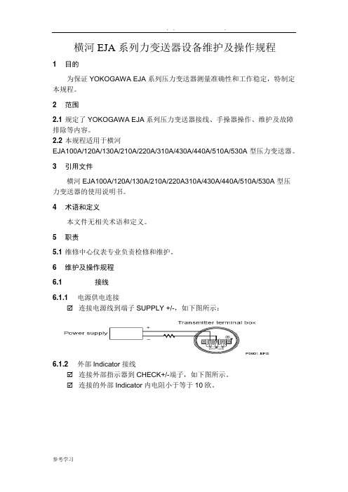
6 维护及操作规程6.1 接线6.1.1 电源供电连接☑连接电源线到端子SUPPLY +/-,如下图所示:6.1.2 外部Indicator接线☑连接外部指示器到CHECK+/-端子,如下图所示。
☑连接的外部Indicator内电阻小于等于10欧。
6.1.3 BT200连接☑连接BT200到SUPPLY+/-。
☑通讯需要串联一个250到600欧的电阻,如下图所示。
6.1.4 Check Meter接线☑连接Check meter到CHECK +/-端子。
☑Check meter内阻小于等于10欧。
☑CHECK+/-端子上4-20mA输出信号,如下图。
6.2 操作规程6.2.1 启动前的准备工作☑检查低压和高压侧工艺压力隔离阀(Tap valve),排污阀,三阀组截止阀,全部关闭。
☑三阀组平衡阀打开。
6.2.2 按照以下步骤投用变送器☑打开低压和高压侧一次隔离阀(Tap valve)使导压管充满工艺介质。
☑缓慢打开高压侧截止阀(Stop valve),使变送器压力检测部分充满液体。
☑关闭高压侧截止阀(Stop valve)。
☑逐步打开低压侧截止阀阀(Stop valve),使变送器检测部分充满工艺液体。
☑关闭低压侧截止阀(Stop valve)。
Yokogawa MAN-series 压力计说明书

Operating InstructionsforManometerModel: MANMANpage 2 MAN 01/11191.Contents1.Contents ........................................................................................................ 22.Note .............................................................................................................. 33.Instrument Inspection .................................................................................... 34.Regulation Use ............................................................................................. 45.Operating Principle ........................................................................................ 46.Mounting ....................................................................................................... 4 6.1. General ................................................................................................ 4 6.2. Assembly for Differential Pressure Manometer .................................... 5 6.3. Assembly for Contact Manometer ........................................................ 5 6.4. Disassembly ........................................................................................ 6 7.Sliding or Magnet-Spring Contacts . (6)7.1. General ................................................................................................ 6 7.2. Contact Ratings ................................................................................... 7 7.3. Over-Current Protection Equipment ..................................................... 8 8.Inductive and Electronic Contacts .. (9)8.1. General ................................................................................................ 9 8.2. Mode of Operation ............................................................................... 9 8.3. Electrical Data – Inductive (NAMUR) Contact .................................... 10 8.4. Electrical Data - Electronic Contact ................................................... 10 missioning.. (10)9.1. General .............................................................................................. 10 9.2. Adjustment of Set-Point Value with Contact Manometers .................. 11 10. Maintenance .. (11)10.1. Cleaning ............................................................................................. 11 11. Technical Information .................................................................................. 11 12. Declaration of Conformance ....................................................................... 12 Manufactured by:Sold by: KOBOLD Instruments Inc.1801 Parkway View Drive Pittsburgh PA 15205-1422Tel.: 412-788-2830Fax: 412-788-4980E-Mail:******************Internet: Kobold-Messring GmbH Werk II Druck- und Temperaturmesstechnik Mahdentalstraße 44 D-71065 Sindelfingen Tel.: 07031-8677-0Fax: 07031-8677-40e-mail:*********************MANMAN 01/1119 page 32.NotePlease read these operating instructions before unpacking and putting the unit into operation. Follow the instructions precisely as described herein.The devices are only to be used, maintained and serviced by persons familiar with these operating instructions and in accordance with local regulations applying to Health & Safety and prevention of accidents.When used in machines, the measuring unit should be used only when the machines fulfil the EC-machine guidelines.PED 2014/68/EUIn acc. with Article 4 Paragraph (3), "Sound Engineering Practice", of the PED 2014/68/EU no CE mark.PipeModelP max/barDiagram 7 Group 2 no dangerous fluids Diagram 6 Group 1dangerous fluids MAN < 200 Art. 4, § 3 Art. 4, § 3 MAN < 500 Art. 4, § 3 Cat. I MAN < 1000 Art. 4, § 3 Cat. I MAN>1000Cat. ICat. I3.Instrument InspectionInstruments are inspected before shipping and sent out in perfect condition.Should damage to a device be visible, we recommend a thorough inspection of the delivery packaging. In case of damage, please inform your parcel service / forwarding agent immediately, since they are responsible for damages during transit.The packing material must be thoroughly searched, so that no accompanying accessories are thrown away.MANpage 4 MAN 01/11194.Regulation UseThe units of the model MAN serve to measure and monitor pressure-dependent processes in machines systems.If applicable, the existing cap-holder on the connection body should only be removed immediately before connecting measurement conductors, so that no foreign particles may enter the pressure chamber. The storage of any measurement unit should be in a dry and dust-free area.5.Operating PrincipleDepending on the measuring range as well as the method of measurement (capsule, diaphragm, bourdon), the pressure to be measured is displayed via a mechanical pointer apparatus. The measuring element deforms in flexible range.6.Mounting6.1. GeneralThe assembly has to be carried out following the corresponding general technical regulations for pressure measuring devices (e.g. DIN 16255 or EN 837-2).While screwing in at the connection point, the required force must not be applied using the housing, instead only use the key areas designated for this purpose.The installation location of the pressure-gauges should be easily accessible and close to the gas pressure measurements; if possible, above the measuring point. To avoid display deceleration time the distance between pressure withdrawal and pressure connection should be kept small.Between the pressure withdrawal point and the measuring unit, a shut-off device should be introduced which allows a renewal and null-point check of the running system. Up to the final commissioning, the shut-off equipment should remain closed in the measurement piping. If pressure peaks are expected, suitable protective equipment may be considered, such as a pressure peak suppressor or a similar device. Alternatively, pressure measuring units with damping-liquid fillingsuch as a glycerine manometer may be provided.MANMAN 01/1119 page 5The piping up to the measuring unit should provide a vibration-free, stable attachment; otherwise, a wall bracket or some additional fortification via an attachment rim on the housing should be provided. Alternatively, mounting in an instrument panel may be considered.The attachment of the manometer is to be executed in such a way that the admissible operating temperature does not violate min. and max. limits. In addition, measurement and stop valve should be protected through sufficiently long dimensional piping or water-bag pipes. The temperature conditions can influence the display accuracy.With gauges for gas measurements, accumulation of condensation is to be avoided by a suitable piping design. If the device for operational reasons cannot be attached above the measuring point, a drainage possibility is to be provided. An additional liquid column may affect the gauge only if this pressure is noted on the scale. In the unfavourable case, the result of measurement is falsified.For sealing of measuring unit's connections, sealing disks or sealing-edge-rings are utilised. The connection is recommended with stress-sockets or union-nuts; with that the manometer can be placed in the best reading position. During screw-in or screw-out, the force must not be exerted on the manometer housing, rather applied only over the four hexagonal connection-clips.Before attaching the gauges, the measuring piping should be cleaned with the Medium to be measured or with clean compressed air. While squeezing off or blowing through the piping or containers, the gauge may not be over-pressed. If the expected pressure is higher, the manometer must be removed or locked off.6.2. Assembly for Differential Pressure ManometerPressure-difference manometers have two pressure connections.On + marked pressure connection, connect high pressure side, on - marked pressure connection, connect low pressure side. In order to protect the unit, a pressure equalization valve manifold MUST be used. Equalization valve manifolds are available from Kobold Instruments.6.3. Assembly for Contact ManometerIn order to avoid bouncing of closed switch and thus resulting increase in wear, care should be taken during installation such that the units remain vibration-free. If excessive vibration exists, the manometer should be isolated from the vibration via a tubing line of flexible capillary. The units should be protected against coarse contamination strong variations of ambient temperature.MANpage 6 MAN 01/11196.4. DisassemblyBefore disassembling the gauge unit, ensure the machine/equipment is depressurized or that the gauge is thoroughly isolated from the system. If possible, the measuring pipe should be emptied. In case of diaphragm type manometers, upper and lower flanges should not be loosened. Hydraulic liquid inside disassembled measuring unit can be dangerous for the environment, in which case corresponding safety precautions should be used. Pressure-measuring units, whose measuring elements are filled with water or water-based chemicals, must be protected from freezing.7.Sliding or Magnet-Spring Contacts7.1. GeneralThe built-in limit switches (Sliding or magnet-spring contacts) are field adjustable via a rotator on the gauge face. The contacts are actuated by the pointer indicator as it moves up and down scale.Pay attention during assembly, commissioning and operation of these units that the applicable national safety regulations (such as VDE 0100) are complied with. All work must be carried out while the system is disconnected from the power supply.∙The electrical connections may only be completed by qualified personnel.∙Make sure that the electrical supply lines are de-energized.∙The connection assignments and the switching functions are given on the type-label of the unit and the connection terminals (1…6) as well as the ground terminals are tagged accordingly. The power supply leads must be sized to accommodate the maximum current carrying rating of the switch and should follow IEC 227 or IEC 245.Not observing the relevant regulations can result in serious lifeand/or material damage.MANMAN 01/1119 page 77.2. Contact RatingsTable 1: Sliding or magnetic spring contact ratingsLimit-value for contact loading with resistive load Sliding ContactMagnet-spring contact unfilled unitsUnfilled unitsFilled units Max. op. Voltage U eff 250 V 250 V 250 V Max. op. CurrentConnecting current 0.7 A 1.0 A 1.0 A Interrupting current 0.7 A 1.0 A 1.0 A Continuous current 0.6 A 0.6 A0.6 APower dissipation 10 W / 18 VA30 W / 50 VA20 W/20 VANote: Under no circumstances, the limiting values of voltage, current or power may be exceeded!Table 2: Recommended contact rating with different supply voltages and device versionsSliding contact Magnet-spring contact Unfilled housingUnfilled housingFilled housingVoltage Resistive Inductive Resistive Inductive Resistive Inductive AC / DC Load loadload load load load AC DCAC DCAC DCcos ϕ > 0.7cos ϕ > 0.7cos ϕ > 0.7V mA mA mA mA mA mA mA mA mA 230 40 45 25 100 120 65 65 90 40 110 80 90 45 200 240 130 130 180 85 48 120 170 70 300 450 200 190 330 130 24200350100400600250250450150At low voltages, on grounds of switching safety, the switching current may not be less than 20 mA.For higher loads and, as well as for the units with liquid -filled housings, in order to protect against oil turbidity, we recommend the use of an additional protective contact relay.MAN7.3. Over-Current Protection EquipmentThese devices do not contain built-in over-current protection. In case, over-current protection is required, we suggest the following values to be considered in accordance with EN 60 947-5-1.Table 3: Over-current protection deviceVoltage Sliding contact Magnet spring contact24 V 1 A 2 A250 V 0.315 A 1 Apage 8 MAN 01/1119MANMAN 01/1119 page 98.Inductive and Electronic Contacts8.1. GeneralInductive contacts (Electronic limit-signal generators, DIN 19234 or NAMUR) are simply DC voltage switches in two-wire form that only contain transistor oscillators.For the operation of inductive contacts, the use of switching amplifier, such as REL-6000 is recommended.Electronic contact (electronic limit-signal generator in three-wire form) are simple inductive DC voltage switches for switching of DC loads up to 100 mA.Pay special attention during assembly, commissioning and operation of these units such that applicable national safety regulations are followed, for example, VDE 0100 etc. All work must be performed while the power is disconnected from the system.∙The electrical connections may only be conducted by qualified personnel.∙Make sure, that the electrical connection wires are de-energized.∙The connection terminals and switching functions are given on the type-label and the connection terminals (1...6) as well as the grounding terminals are accordingly marked. The wires provided for supply connection must be appropriate for the largest current handling capability by the switch and should follow IEC 227 or IEC 245.Not complying with the applicable regulations, serious damage to life and materials may result.8.2. Mode of OperationThe proximity switches, due to their slit-groove construction are also known as slit-initiators. The electromagnetic field is concentrated between two coils, which face each other axially. The switch responds if the measuring pointer moves an aluminium target into the air-gap between both the coils (slit). This results in switch activation.With inductive contacts, if there is no damping material present within the slit-range, oscillator swings. In this state, system has a very low resistance (approx. 1k Ω).When the target enters the air-gap, the coil system is damped, the oscillations in the oscillator are set up and the system becomes more resistive (approx. 7k Ω).MANpage 10 MAN 01/11198.3. Electrical Data – Inductive (NAMUR) ContactNominal voltage 8 V DC (Ri approx. 1 k Ω) Self-inductivity 29 μH Self-capacitance20 nF Current-intake (active surfaces free) ≥ 3 mA Current-intake (active surfaces covered)≤ 1 mA8.4. Electrical Data - Electronic ContactOperational voltage 10...30 V DC Residual ripple 10 %No load current ≤ 10 mAPolarity protection Restricted (Ub) Inductive protection 1 kV; 0.1 ms ; 1k Oscillator frequency1000 kHz EMV DIN 60947-5-2 supplement ZA YesSwitching frequency 1000 Hz OutputPNP Switching element function N.O.Switching current ≤100 mA Residual current≤ 100 μA Voltage drop (at Imax.)≤ 0.7 Vmissioning9.1. GeneralPressure should be applied to the gauge slowly, in order to avoid damage to the measuring unit. Thereby the unit must be monitored continuously. The maximum permitted pressure must not be exceeded.After commissioning of the unit, all piping connected to the measurement unit must be checked for proper sealing. Moreover, if present, the shut-off valve for the system pressure at the pressure-intake point must be closed.The pointer moves in the null-point direction (possible temperature changes, condensation, to be considered), check also if the leakage exists.Attention! With dangerous materials, such as Oxygen, Acetylene, flammable or poisonous materials, as well as chillers, compressors etc. all the general regulations, along with the existing relevant regulatory directions must be observed.MAN9.2. Adjustment of Set-Point Value with Contact ManometersThe adjustment of desired value (set-point value) is carried out via the suppliedadjustment key which is inserted into the back of the contact electrical plug. Theadjustment is made be inserting into the centre of the gauge face and rotating thecontact pointer to the setpoint value. The switching point should be tested atoperating pressure due to different hysteresis behaviours, particularly withmagnet spring contact.For reasons of hysteresis, switching accuracy, switching safety and the working-life of mechanical measuring systems, the switching points however should notbe set in the range 0 to 10% and 90 to 100% of respective measurement span.10.MaintenanceIf the medium to be measured is not contaminated, the unit is maintenance-free.An examination of the display and the switching function should take place about1 to2 times per year. In order to check the display and switching function, thedevice is to be separated from the process and be subjected with a test pressurewith appropriate inspection temperature.10.1. CleaningClean the devices with a dry or soap-water solution dampened cloth. If theelectrical connections require cleaning make sure the power is disconnected first.Before restarting, it must be guaranteed that all parts are dried.11.Technical InformationSee "order confirmation" and data sheet.MAN 01/1119page 11MAN12.Declaration of ConformanceWe, Kobold Messring GmbH, Hofheim-Ts, Germany, declare under our sole responsibility that the product:Manometer with Inductive and Electronic Contacts Model: MANto which this declaration relates is in conformity with the standards noted below:EN 50581:2012Technical documentation for the assessment of electricaland electronic products with respect to the restriction ofhazardous substancesAlso the following EU guidelines are fulfilled:2011/65/EU RoHS II (category 9)Additional for MAN pmax > 200 bar2014/68/EU PEDCategory I, Table 6, pipe, gasesGroup 1 dangerous fluids∙Module D, marking CE0575∙Notified body: DNV GL∙Certificate No. PEDD000000RAdditional for MAN pmax > 1000 bar2014/68/EU PEDCategory I, Table 7, pipe,Group 2 non dangerous fluids∙Module D, marking CE0575∙Notified body: DNV GL∙Certificate No. PEDD000000RAdditional for MAN-..S/M/I/P:is in conformity with the standards noted below:EN 60947-1:2015 Low-voltage switchgear and controlgear - Part 1: Generalrulespage 12 MAN 01/1119MANMAN 01/1119 page 13 Also the following EC guidelines are fulfilled: 2014/35/EULow Voltage Directive 2014/30/EU EMC DirectiveHofheim, 21 Nov. 2019H.PetersM.Wenzel General Manager Proxy Holder。
恒河压力变送器说明书

用户手册IM1C21B1-01CY第九版IM1C21B1-01CYEJA110A差压变送器EJA120A微差压变送器EJA130A高静压差压变送器User’sManual目录1.前言………………………………………1-11.1安全预防………………………………1-21.2质保……………………………………1-22.使用注意事项……………………………2-12.1型号规格确认…………………………2-12.2拆包……………………………………2-12.3保管……………………………………2-12.4安装场所………………………………2-12.5加压……………………………………2-12.6电气接口的防水处理…………………2-22.7无线电收发机的使用限制……………2-22.8绝缘电阻与耐电压测试………………2-22.9防爆型变送器的安装…………………2-22.9.1NEPSI防爆许可…………………2-22.9.2FM防爆许可……………………2-42.9.3CSA防爆许可……………………2-52.9.4IECEX防爆许可…………………2-62.9.5CENELECATEX牗KEMA牘防爆许可………………………………2-72.10EMC一致性标准牶…………………2-102.11PED牗压力设备指导牘………………2-102.12低电压指导…………………………2-103.部件名称…………………………………3-14.安装………………………………………4-14.1注意事项………………………………4-14.2安装……………………………………4-14.3过程接口的变更………………………4-24.4高低压侧的转换………………………4-34.4.1180°旋转测压部法……………4-34.4.2BT200智能终端使用方法……4-34.5转换部的旋转…………………………4-35.导压管的配装……………………………5-15.1配装导压管的注意事项………………5-15.1.1导压管与变送器的连接………5-15.1.2导压管的配装方法……………5-25.2导压管配管示例………………………5-26.配线………………………………………6-16.1配线注意事项…………………………6-16.2电缆线选定……………………………6-16.3外部接线盒的连接………………………6-16.3.1电源连接……………………………6-16.3.2外接指示计的连接…………………6-16.3.3BT200智能终端的连接…………6-26.3.4校验仪表的连接…………………6-26.4配线……………………………………6-26.4.1回路结构…………………………6-26.4.2配线安装…………………………6-26.5接地……………………………………6-36.6电源电压与负载电阻…………………6-37.操作………………………………………7-17.1启动准备………………………………7-17.2零点调整………………………………7-27.3启动……………………………………7-27.4停机……………………………………7-27.5测压部排液汽…………………………7-27.5.1排液……………………………7-37.5.2排气……………………………7-37.6测量范围设置…………………………7-48.智能终端BT200的操作………………8-18.1BT200操作注意事项…………………8-18.1.1BT200的连接……………………8-18.1.2通讯线路状况……………………8-18.2BT200的操作方法……………………8-18.2.1键面排列……………………………8-18.2.2操作键的功能………………………8-28.2.3用操作键调示菜单…………………8-38.3BT200的参数设置……………………8-48.3.1参数总表……………………………8-48.3.2参数意义和选择……………………8-68.3.3参数设置……………………………8-7牗1牘位号设置……………………………8-7牗2牘测量范围设置………………………8-7牗3牘阻尼时间常数设置…………………8-8牗4牘输出信号和内藏显示计显示模式设置……………………………………8-9牗5牘输出信号低截止模式设置…………8-9牗6牘内藏指示计显示选择与设置……8-9牗7牘温度单位显示设置…………………8-11牗8牘静压单位显示设置…………………8-11牗9牘正/反方向输出设置……………8-11牗10牘取压方向设置……………………8-11牗11牘CPU异常时的输出状态显示设置…………………………………8-12牗12牘硬件异常时的输出状态设置…8-12牗13牘双向流体测量设置…………………8-12牗14牘实际输入时量程改变的设置……8-12牗15牘零点调整………………………8-13牗16牘输出测试设置…………………8-14牗17牘用户存储区………………………8-148.4BT200数据显示………………………8-158.4.1显示测量数据……………………8-158.4.2显示变送器型号和规格………8-158.5自诊断………………………………7-158.5.1故障检查…………………………8-158.5.2错误与纠正………………………8-179.维修………………………………………9-19.1概述……………………………………9-19.2校验仪表的选用………………………9-19.3校验……………………………………9-19.4拆卸与再安装…………………………9-39.4.1替换内藏指示计…………………9-39.4.2替换CPU组件……………………9-49.4.3清洁和替换膜盒组件……………9-49.4.4替换过程接口垫圈………………9-59.5故障排除………………………………9-69.5.1基本故障的排除…………………9-69.5.2故障排除流程图…………………9-610.一般规格………………………………10-110.1标准规格………………………………10-110.2型号和规格代码……………………10-310.3附加规格一览表……………………10-610.4外型尺寸………………………………10-8用户维修部件清单DpharpEJA系列变送器转换部………………………………IM1C21B1-01CYEJA110A差压变送器………………………………IM1C21B1-01CYEJA120A差压变送器………………………………IM1C21B1-01CYEJA130A差压变送器………………………………IM1C21B1-01CY1.前言有关FOUNDATION现场总线和HART通讯协议请参见IM01C22T02-01E和IM01C22T01-01E感谢您使用DpharpEJA智能式压力变送器,Dpharp智能式压力变送器在出厂前已进行准确的调校。
横河川仪变送器手操器说明书

Users ManualYHC 4150X 系列 HART® 通讯器YHC 4150X HART ®通讯器IM 61A YHC1-E-A 第三版: 2008年5月YHC 4150X HART 通讯器用户手册重要提示产品的重要信息都包含在本手册中,在操作前请仔细阅读手册全部内容。
为保证操作者和系统的安全,在调试、使用或维护产品前,必须彻底理解本手册内容。
辅助信息要获得用户支持,请与当地横河公司事务所、代表或代理商直接联系。
要获得各地代表名单及联系方式,请访问我们的网站 。
HART®是HART通信基金会的注册商标。
YHC 4150X HART 通讯器用户手册目录YHC 4150X 通讯器概述 (1)显示器 (1)标题栏符号 (2)键盘 (2)字母数字/符号输入 (3)左 / 右箭头键 (4)软键 (4)翻查操作键 (5)一般操作 (5)电源选项 (5)通讯/AC适配器 (5)菜单导航 (6)启动 YHC (6)YHC主菜单显示 (8)YHC组态设置 (8)1 用户 (8)2 应用 (8)3 锁定(锁定、PV Prompt设定、锁定详细资料) (8)锁定代码 (8)解除锁定 (9)锁定代码更改 (9)4 时钟/定时器 (9)1 时钟编辑 (9)2 背光 (10)3 关闭定时器 (10)5 其它 (10)1 型号 (10)2 电池型号选择 (10)3 HART通讯模式选择 (10)4输入PC通信模式 (10)5轮询类型: 自动(默认地址0)或数字(默认地址0-15) (11)电池安装/拆卸 (YHC所有型号) (12)外部连接 (12)通讯/AC 适配器连接 (12)HART 接线插座 / 导线设置 (13)危险场所使用 (14)本质安全操作 (14)YHC 4150X HART®通讯 (15)HART 命令 (15)HART 连接 (15)HART 通信 (16)初始屏幕 / 在线模式 (16)多点轮询(地址1-15) (17)数字轮询 (地址1-15) (17)自动和数字轮询默认值设置 (17)零地址设备手册发布 (18)离线菜单模式 (18)1 DOF文件列表 / 显示 (18)2组态列表 / 编辑 (18)3 组态创建 (19)4 组态删除 (19)删除单个组态 / 清除组态内存 (19)在线设置模式 (20)通信故障检查 (21)更多状态信息 (21)保存 / 发送组态功能 (21)DOF 存储器维护 (22)使用横河DMS软件编制HART组态文件 (23)YHC 4150X特殊和普通HART通讯 (23)普通HART通讯应用 (23)YHC 4150X固件和DOF文件更新 (24)概述 (24)谁可以使用下载地址 (24)对PC机的要求 (24)YHC更改准备 (24)使用DPC管理程序更新YHC (24)直接使用DOF下载网站 (25)使用DOF下载网站和DPC管理程序更新YHC (26)YHC 维修 (28)附录YHC 技术规格 (29)YHC 型号, 选项, 订货信息 (30)YHC 附件表 (30)本质安全型控制文件 (31)EC一致性声明 (32)HART命令菜单树 ........................................................................................................................33-34 普通(HART 5) .. (33)EJA Rev 2 (34)YHC4150X HART 通讯器概述YHC 4150X HART 通讯器是一种全功能HART 通讯器, 支持通用命令、普通命令和设备特殊命令,可以完成设备的调试、组态和维护。
- 1、下载文档前请自行甄别文档内容的完整性,平台不提供额外的编辑、内容补充、找答案等附加服务。
- 2、"仅部分预览"的文档,不可在线预览部分如存在完整性等问题,可反馈申请退款(可完整预览的文档不适用该条件!)。
- 3、如文档侵犯您的权益,请联系客服反馈,我们会尽快为您处理(人工客服工作时间:9:00-18:30)。
YOKOGAWA压力变送器常用型号
EJA110
EJA510/EJA520
EJA210
EJA438
EJA118
YOKOGAWA压力变送器型号解析举例
1 2
变送器概述 变送器安装
3 4
变送器组态 使用和维护
5
故障检修
6
案例分析
YOKOGAWA压力变送器的安装
Байду номын сангаас
用差压变送测量气体流量
TRANSMITTER
PZ= PD- PJ
二、压力检测方法
1.平衡法:通过仪表使液柱高度的重力或砝码的重量与被 测压力相平衡的原理测量压力。
2.弹性法:利用各种形式的弹性元件,在被测介质的表压 力或负压力作用下产生的弹性变形来反映被测压力的 大小。
3.电气式:用压力敏感元件直接将压力转换成电阻、电荷 量等电量的变化。
采用 HART protocol® (HART 协议) YOKOGAWA EJA系列压力变送器
Vent Plug Vent Valve
手动阀通常安装靠下 边的地方
TX
Drain Valve Drain Plug
YOKOGAWA压力变送器的安装
用差压变送器测量蒸汽流量
Orifice
Condensate Pot
3 Valve Manifold
TX
手动阀通常安装在靠 上边的地方
Drain Valve Drain Plug
YOKOGAWA压力变送器的安装
用压力变送器测量开口桶槽液位
Fill Plug
Open Tank
Tap Valve
如果测量液体腐蚀性太大 ,要使用隔离液
隔离液的密度必须比 被测液体大
TX
Transmitter
Drain Valve Drain Plug
Open Tank
YOKOGAWA压力变送器的安装
YOKOGAWA压力变送器介绍
一:概述
压力定义: 垂直作用在单位面积上的力称压力。在国
际单位制(SI)和我国法定计量单位中,压力 的单位是“帕斯卡”,简称“帕”,符号为 “Pa”1 。P a1 N /m 21m kg 2 m s21 kgm 1 s 2
即1N的力垂直均匀作用在1m2的面积上所形成 的压力值为1Pa。
压力单位
过去采用的压力单位“工程大气压力” (kgf/cm2)、“毫米汞柱”(mmHg)、“毫米水柱”
((mbamrH)2O、)“、PS“I”物等理均大应气改成压法”定(计at量m单)位、帕“。巴 ”
1 kgf/cm2 = 0.9807×10⁵Pa 1mmH2O = 0.9807×10Pa 1 mmHg = 1.332×10²Pa
Metal Resonant Wire金属丝谐振
Silicon Resonant 硅谐振式
Force Balance 力平衡式
单晶硅谐振式差压变送器
YOKOGAWA压力变送器传感器
硅谐振传感器
硅谐振式差压变送器工作原理
信号终端
低压腔
谐振传感器 高压侧(HP)
低压侧 (LP)
硅片 高压强
P1
硅油受压后可流动性和不可压缩性
用差压变送器测量液位
1atm = 1.01325×10⁵Pa
1bar=105Pa 1PSI=6.89×10³Pa
压力表示方式
绝对压力PJ :直接作用于容器或物体表面的压力,称为“绝对压力”,绝对压 力值以绝对真空作为起点,符号为PABS(ABS为下标)。 大气压力PD :地球表面覆盖有一层厚厚的由空气组成的大气层。在大气层中的物体,
DpHarp EJA
Digital Pressure Transmitter
变送器总体分类
差压变送器
表压/绝压变送器
气体或液体测量
变送器测量介质分类
气体测量
蒸汽测量
Pressure Sensor Of Transmitter
Capacitance 电容 PiezoResistance 压电电阻式
TX
3 Valve Manifold
Vent Plug Vent Valve
Tap Valve
手动阀通常安装在靠 上边的地方
Tap Valve Orifice
TX
Drain Valve Drain Plug
YOKOGAWA压力变送器的安装
用差压变送器测量液体流量
Tap Valve
TX
3 Valve Manifold
都要受到空气分子撞击产生的压力,这个压力称为大气压力。
表压力 PB :压力表原理
1.1原理:压力表通过表内的敏感元件(波登管、膜盒、波纹管)的弹性形变,再由表 内机芯的转换机构将压力形变传导至指针,引起指针转动来显示压力。
PB= PJ -PD 真空度PZ(负压) :补充的全面解释:
“真空度”顾名思义就是真空的程度。所谓“真空“,是指在给定的空间内,压强低于 101325帕斯卡(也即一个标准大气压强约101KPa)的气体状态。 在真空状态下,气体的稀薄程度通常用气体的压力值来表示,显然,该压力值越小则表 示气体越稀薄。
电容式差压变送器工作原理
电容式差压变送器工作原理
电容式差压变送器工作原理
被测介质的高低压力分别进入测量元件的高低压室,作用于隔离膜片上, 填充液把两隔离膜片的压力信号传送到中心测量膜片上,中心测量膜片是一 个张紧的弹性元件,作用在其上的两侧压力差使中心测量膜片产生一个对应 于压力差的变形,其变形位移与所测压力差成正比,这个位移使电容极板产 生相应的电容变化,电子线路检测到这一电容变化并放大转换成对应的电流 信号。如果低压室通大气,高压室接被测介质,这时就可测量介质的相对压 力。同样,如果低压室为真空,高压室接被测介质,这时就可测量介质的绝 对压力。
硅谐振式差压变送器工作原理
❖ 采用微电子加工技术(MEMS)在一个单晶硅芯片表面的中心和边缘制作两 个形状、尺寸、材质完全一致的H形状的谐振梁,谐振梁在自激振荡回路中 作高频振荡(如图1)。 单晶硅片的上下表面受到的压力不等时,将产生形 变,导致中心谐振梁 因压缩力而频率减小,边缘谐振因受拉伸力而频率增 加(如图2)。
❖ 两频率之差信号直接送到CPU进行数据处理,然后 (1)经D/A转换成420mA输出信号,通讯时叠加Brain或Hart数字信号; (2)直接输出符 合现场总线(Fieldbus Foundation TM)标准的数字信号。
❖ 当加有静压(工作压力)时,两形状、尺寸、材质完全一致的谐振梁形变相 同, 故频率变化也一致,故偏差自动清除。