液化石油气汽车的使用与调整实用版
LNG车辆使用操作资料

第二单元 供气系统结构原理
LNG气瓶工作原理图
第二单元 供气系统结构原理
并再次检漏液体温度太低或质量问题检验液体质量和温度充液前后压力表无反应压力表坏更换压力表安全阀开启压力表无反应压力表坏更换压力表气瓶头部结霜可能在用气正常现象可能有管件泄露检查再按操作规程检修瓶体冒汗或结霜环境温度过低空气湿度大正常现象真空失效返回本公司维修第八单元常见故障及处理措施故障现象原因分析解决方案安全阀开启液体存放时间过长立即用气或放空增压快检查气瓶是否正常安全阀设定压力低或故障按操作规程更换安全阀液位显示零位气瓶内液体已用完往气瓶内按规定量充液转换器设置不当重新设置转换器电容值显示器或转换器损坏检查各部件维修或更换瓶内液体用完后液位显示满位转换器设置不当重新设置转换器电容值显示器或转换器损坏检查各部件维修或更换导线断路或连接口等渗水检查导线将水份弄干重新设置连接供气温度过高或过低供热水原因调准热水供应量供气压力过高或过低经济阀管路调压阀检查设定压力是否准确工作是否正常发动机不工作气瓶内气液已用完往瓶内充液供液阀门未打开找开供液阀门发动机电磁阀未打开或故障检查供电是否正常电磁阀是否完好第八单元常见故障及处理措施故障现象原因分析解决方案加气时瓶内压过高加气设备设定压力过高把加气设备调节器致适当压力
缓冲罐 1、低温环境下能进一步加热低温LNG,使 其充分汽化,利于发动机冷启动; 2、缓冲发动机工况急剧变化导致的供气管 路压力波动,对供气压力稳定性有一定作用。
稳压器
主要作用在于:当气瓶内液体温度升高 时,气瓶最高压力可能超过16bar。而 玉柴发动机最高使用压力为13.8bar, 超过该压力可能导致电控调压器失效、 发动机无法启动、游车、催化器烧结
液化石油气汽车装车操作规程

液化石油气汽车装车操作规程1. 引言本文档旨在规范液化石油气(LPG)汽车装车操作,以确保装车过程的安全性和高效性。
液化石油气是一种具有较高的能量密度的燃料,广泛应用于汽车等交通工具,但其在贮存和使用过程中存在一定的安全风险。
因此,制定本规程对于保障人身安全和装车效率至关重要。
2. 装车前的准备工作在进行液化石油气汽车的装车操作之前,必须进行以下准备工作:2.1 装车设备的检查确保装车设备的正常运行和完好无损,包括液化石油气储罐、输送管道、阀门、计量装置等。
检查设备是否有泄露、渗漏等问题,并进行必要的维修和更换。
2.2 装车环境的检查检查装车环境是否符合安全要求,包括通风情况、燃气泄漏检测设备、火源远离装车区等。
确保装车过程中不存在明火、静电和其他可能引发安全事故的因素。
2.3 装车人员的培训和装备对参与装车操作的人员进行相关培训,了解液化石油气的性质、危险性和安全操作规程。
同时,配备必要的个人防护装备,包括防静电衣物、防护手套、安全帽等。
3. 装车操作流程3.1 装车前的准备1.确保装车设备的检查和维修已经完成。
2.检查装车环境的安全性要求是否满足。
3.确认装车人员已经接受过必要的培训并佩戴个人防护装备。
3.2 车辆准备1.停稳车辆,并将发动机熄火。
2.关闭车辆的全部电气设备和明火。
3.3 车辆连接1.将装车枪与车辆燃料进气口连接,并确保连接牢固。
2.检查连接部位是否有泄漏迹象,如有,立即停止装车,并进行检修。
3.4 装车操作1.打开液化石油气储罐的阀门,确保燃料流通。
2.打开计量装置,开始进行燃料计量。
3.根据车辆所需燃料量调节计量装置,并监控燃料流速。
4.在装车过程中,保持注意力集中,严禁离开装车现场或分散注意力。
5.在达到车辆所需燃料量后,关闭液化石油气储罐阀门和计量装置。
6.检查装车枪和车辆燃料进气口的连接,确保连接牢固。
7.根据需要记录装车量和装车时间。
3.5 装车后的处理1.将装车设备归位,关闭相应的阀门。
液化石油气(LPG)—汽油双燃料汽车的气量调节

K e r s: a —u l d a o bi LPQ ; miso y wo d du f e e utmo l l e; , e s in
1 概 述
液 化石油 汽 (P L G)一 汽 油 双 燃 料 汽 车 是 指 在 汽 油 车 的 基 础 上配 装 贮 气 、 气 系 统 改 装 而 成 的 既 可 以使 用 供
性质 不 同 , 混 合 比 必 然 不 同 ( 合 比 是 液 化 石 油 气 其 混
3 可 燃 混 合 气 的 混 合 比计 算
( )计 算 参 数 1
表 l 标 准 状 况 下 空 气 的 密 度 J = 12 3 gm 成 分 0 .9 k/ 3
(P L G)一 汽 油 双 燃 料 汽 车 的 关 键 技 术 参 数 ) 且 它 的 调 , 节 是 否 恰 当将 直 接 影 响 L G汽 车 的整 车 性 能 。 P
l 化 油 = 摩 尔 质 量 / 尔 体 积 D 石气 液 摩
=
0.  ̄ k / 0 4 0 g 0. 22 m
作 者简 介 : 李辉 (9 0一) 男 , 17 , 工学学 士, 哈尔 滨 飞机制 造集 团机 电公 司机电设 计研 究所 助 理工 程师 从 事 机 械 设 计 工 作 。
维普资讯
第 2 0卷 , 第 1 5期 总 1 20 0 2年 9月 , 5期 第
《节 能 技 术 》
ENERGY C0NSERVATI ON TECHN0 n 0GY
Vo . O. u No. 1 1 2 S m 15 S pt 2 0 No. e . 0 2, 5
比 以汽 油为燃料 时 , 不但 可 以减 少有 害气体 的排 放量 , 而且 还可 以降低 发动机噪 声 。
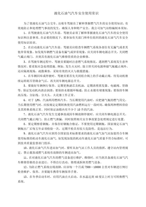
LP-6 液化石油气柴油车使用与维护手册说明书
LP-6 M ODEL L IQUEFIED P ETROLEUM G AS C YLINDER T RUCKU SE & M AINTENANCE M ANUALV ESTIL M ANUFACTURING C ORP .2999 N ORTH W AYNE S TREET P.O. B OX 507, A NGOLA , IN 46703T ELEPHONE : (260) 665-7586 -OR - T OLL F REE (800) 348-0868F AX : (260) 665-1339U RL : WWW .VESTILMFG .COM E MAIL : SALES @VESTIL .COMNOTE: Compliance with regulations, codes, and/or statutory (non-voluntary) standards enforced in thelocation where the cylinder truck is used is exclusively the responsibility of the end-user.Table of ContentsTable of FiguresProduct Introduction (2)FIG. 1 “Exploded parts diagram”................... ...................... 3 Safety Principles............................................. 2 FIG. 2A “Loading cylinders onto racks: side view”.................. 4 Use Instructions.............................................. 4 - 5 FIG. 2B “Rack spring pins”................................................ 4 Load cylinders onto racks........................... 4 FIG. 2C “Overhead view with cylinder racks secured in-line”..... 4 Adjust position of boom & hook arm............. 5 FIG. 2D “Overhead view with cylinder racks rotated”............... 4 Lift a cylinder with hook arm....................... 5 FIG. 3 “Floor lock”............................................................ 4 Inspections & Maintenance............................ 5 FIG. 4A “Manually-operated hydraulic pump”......................... 5 Hand-Operated Hydraulic Pump.................. 6 FIG. 4B “Close-up of pump body”....................................... 5 Product Labels............................................ 7 FIG. 5 “Engaging cylinder with load hooks”........................... 5 FIG. 6 “Hydraulic pump exploded parts diagram.. (6)FIG. 7 “Label placement diagram” (7)Product IntroductionThank you for purchasing a model LP-6 liquefied petroleum gas cylinder truck, referred to in this manual as “cylinder truck,” “truck” or “product”. Our cylinder trucks are durable, high-quality productsrigorously engineered for dependability and simplicity. Although use and maintenance are intuitive,any person who might use or maintain this product should be familiar with the instructions provided inthis manual.LP-6 cylinder trucks provide a means lifting and transporting as many as 6 LPG cylinders. Our design includes a mast that can freely rotate in a full circle. The mast supports a manually-operated hydraulic pump, and the pump raises and lowers the load-lifting boom. Other features include: 1) a cylinder hook arm (see items no. 9, 21-24 on p. 3) at the end of the boom designed to simultaneously engage the top and bottom ends of an LPG cylinder; 2) built-in racks to secure LPG cylinders during transport (2 empty cylinders in the vertical position and 4 full cylinders in the horizontal position); 3) two rigid and two swivel casters for smooth movement; 4) welded steel construction with a paintedfinish.Dimensions and other product specifications appear in the following table:Model Maximum numberof cylinders DescriptionOverall dimensions (W x Lx H) in inches (~cm)Caster (wheel)specificationsNet weight inpounds (~kg)LP-6 6LPG cylinder truck 33 x 80 x 73~(84 x 203.2 x 185.4)8 in. tall; 2in. wide20.3cm x 5.1cm750(341kg)Safety PrinciplesVestil Manufacturing Corp. recognizes the critical importance of workplace safety. However, although Vestil diligently strives to identify foreseeable hazardous situations, this manual cannot address every conceivable danger. The end-user is ultimately responsible for exercising sound judgment at all times.This manual will acquaint persons authorized to install and/or maintain this cylinder truck with proper installation and maintenance procedures. Therefore, each person, who might use or perform maintenance on the cylinder truck, must read and understand every instruction BEFORE using the device or performing maintenance. Users should have access to the manual at all times and should routinely review the directions.This manual uses SIGNAL WORDS to classify personal injury risks and situations that might lead to property damage, as well as to draw attention to safety message(s). The reader must understand that each signal word indicates the seriousness of the identified hazard.Identifies a hazardous situation which, if not avoided, WILL result in DEATH or SERIOUSINJURY. Use of this signal word is limited to the most extreme situations.Identifies a hazardous situation which, if not avoided, COULD result in DEATH or SERIOUSINJURY.Indicates a hazardous situation which, if not avoided, COULD result in MINOR or MODERATEinjury.Identifies practices likely to result in product/property damage, such as operation that might damage thecylinder truck.Employers are responsible for training employees to use the product properly. If you do not understand an instruction, ask your supervisor or employer for assistance, because failure to follow the directions in this manual might result in serious personal injury or even death.Vestil is not liable for any injury or property damage that occurs as a consequence of failing to apply either: 1) the instructions in this manual; or 2) the information provided on labels affixed to the product. Furthermore, failure to exercise good judgment and common sense might result in property damage, serious personal injury or death. Such failure is solely the fault of the person(s) using the cylinder truck.FIG. 1: Exploded parts diagramBoom762521141922, 23 & 2431512817 26 2818 & 194510 & 1113121627Vertical cylinderU SE I NSTRUCTIONSThe operating instructions in this manual are intended to supplement LPG cylinder handling practices applied at your worksite. LP-6 cylinder trucks are designed for indoor use.Failure to read and understand the instructions included in this manual before using or maintaining the cylinder truck constitutes misuse . Read the manual, as necessary, to refresh your understanding of the inspection and maintenance procedures explained on p. 5-6. DO NOT attempt to resolve any issue with the product unless you are authorized to do so and are certain that it will be safe to use afterwards.Improper use or maintenance might result in serious personal injury or even death. To reduce the likelihoodof injury:∙ Fully lower the boom and remove the load (cylinder) from the cylinder hook arm (see items no. 9 and 21 on p. 3)BEFORE leaving the crane unattended and BEFORE performing any work on the crane. ∙DO NOT ride on or allow other person(s) to ride or climb on the truck.∙ Instruct everyone to clear the area where the truck will be used including the travel path (if cylinder(s) must be transported). Instruct any person(s) assisting you to avoid contact with the boom while it is loaded and rotated. Never allow any person to get underneath a suspended cylinder.∙ DO NOT attempt to lift a cylinder with the hook arm (see items no. 9 and 21 on p. 3) UNLESS BOTH load hooks securely engage the cylinder (see “Lift a cylinder with the hook arm on page 5). ∙ All labels affixed to the product must be readable and undamaged.∙ Always carefully watch the boom and any suspended cylinder while using the truck to lift cylinders. ∙ ONLY use the truck on even, level surfaces.∙ DO NOT use the cylinder truck if you: 1) observe any warping or deformation of the frame, boom, mast, hooks or hook arm; 2) hear unusual noise during use; 2) notice wheel damage or an uneven wear pattern on any of the wheels; or 3) the pump malfunctions or makes unusual sounds during use. Notify your supervisor and authorized maintenance personnel if you notice anything out of the ordinary.∙ Do not exceed the load rating (capacity)! Injury to personnel or property damage including permanent damage to the truck could result. Rated load data appears in the table on p. 2 and on the capacity label affixed to the truck. (See “Product Labels ”, label #287 onp. 7). The label indicates the net capacity of the cylinder truck when handling a static (stable, non-shifting) load that has a horizontal center of gravity directly under the lifting hook. DO NOT apply any side loads (pull load to the side) to a suspended cylinder.∙ DO NOT modify the truck IN ANY WAY. Unauthorized modifications automatically void the warranty and might make the cylinder truck unsafe to use. L OAD C YLINDER (S ) ONTO R ACKS :The upper cylinder racks can be rotated outward to give access to the lower racks. Spring pins fix the position of each upper rack in either an inline or rotated orientation (see Fig.’s 2C and 2D below). Each of the drawings below pair a view of the truck with the corresponding position of the spring pins below:FIG. 2A : Side viewPlace filled cylinders on the horizontal racks only. Use the vertical cylinder racks (see FIG. 1 on p. 3) to transport empty cylinders. Once loaded, push the cylinder truck to the location where a cylinder(s) will be unloaded. Position the truck as needed, and then immobilize the truck with the floor lock by stepping on the locking lever until the floor lock pad firmly contacts the floor (see FIG. 3). To release the floor lock, press on the unlocking lever.Overhead view with cylinder racksrotatedOverhead view with cylinder rackssecured in-lineFIG 2B: Rack spring pinsSpring pins extended: when extended, the pin fits inside 1 of the 2Spring pins retracted: to retract, pull upward on ring and turn the pin 90°.Press unlocking lever to disengage floor lockPress locking lev to engage floorFIG. 3: Floor lockerFloor lock padA DJUST P OSITION OFB OOM AND H OOK A RMThe boom (items numbered 6 and & in FIG. 1 on p. 3) and mast rotate freely through 360°, i.e. the boom and mast do not lock in position. The manually-operated hydraulic pump adjusts the vertical position of the hook arm. To raise the boom, rotate the release valve lever on the pump body to the position shown in FIG. 4A below and then work the handle back and forth. Lower the boom by opening the release valve. To open the release valve rotate the lever in the opposite direction (direction of arrow in FIG. 4B).The operator can adjust the lowering speed by gradually and only partially opening the release valve, which can be accomplished by slowly rotating the release lever and not rotating it to the fully opened position. The boom is completely lowered when it will not lower further even though the release valve is still open.The boom can be fixed at an elevation between completely lowered and fully raised by closing the release valve as the boom lowers. The boom will maintain vertical position until the release valve is opened again.FIG. 4B: Close-up of pump bodyPlugOil reservoirPump bodyRelease valve leverFIG. 4A: Manually-operated hydraulic pumpL IFT A C YLINDER WITH H OOK A RMApproximately 26in.FIG. 5: Engaging cylinder with load hooksLoad hookLoad hook The hook arm cannot engage cylinders loaded on the racks, because the boom cannot lower far enough to bring the hook arm into contact with cylinders loaded on the upper racks.Instead, someone must lift a cylinder up to the hook arm and another person must engage the top and bottom flanges of the cylinder with the hooks. Therefore, position the hook arm where it will be easy to access before loading it with a cylinder and only lift LPG cylinders that fit securely in the hooks. To fit properly in both hooks, a cylinder should be approximately 26in. (~66cm) tall/long. DO NOT attempt to lift a cylinder that cannot be firmly engaged by BOTH lifting hooks (see FIG. 5 at right). Raise the boom to the height required for the job: 1) close the release valve if it is open (boom fully lowered); 2) move the handle back-and-forth to raise the boom.I NSPECTIONS & M AINTENANCEImproper maintenance or repair may make the crane unsafe to use, which could result in serious personalinjuries or death. DO NOT attempt to repair or maintain the crane UNLESS you are qualified and authorized to do so by your employer.∙ Identify all potential hazards before beginning work, and always scrupulously adhere to worksite safety procedures. ∙ Fully lower and unload the boom BEFORE beginning maintenance/repairs.(A) Inspect daily for [item numbers identified in parentheses refer to FIG. 1 on p. 3]:1.) Oil leaks;2.) Pinched or chafed hoses;3.) Damage or structural deformation to the frame (item #1), the boom (#6 & 7), and hook arm (#9), load hooks (#21);4.) Unusual noise or binding;5.) Pump operates properly.(B) Perform the following inspections and service at least once per month:1.) Oil level. Completely lower the boom; then remove the reservoir plug (see FIG. 3B on p. 5). Oil should be within ¾” of the top of the reservoir. Change the oil if it darkens, becomes gritty, or turns a milky color (indicating the presence of water). Replace with anti-wear hydraulic oil of viscosity grade 150 SUS at 100°F, (ISO 32 at 40°C).Do not use brake fluid or jack oils in the hydraulic system. If oil is needed, use an anti-wear hydraulic oilwith a viscosity of 150 SUS at 100°F (ISO 32 @ 40°C), such as AW 32 or HO 150 hydraulic oil, or a non-synthetic transmission fluid. You may use a synthetic transmission fluid if you flush the system with the synthetic fluid before filling the reservoir.2.) Worn or damaged hydraulic hose.3.) Condition of fasteners/hardware: bolts, nuts, pins, etc.4.) Looseness, wear, or damage to the casters’ bearings, mounting hardware, or surface material.5.) Unusual noises or movement during operation.6.) Labels (see FIG. 7 on p. 7): each label should be clean, readable, and undamaged.H AND -O PERATED H YDRAULIC P UMPIf your pump is new or recently serviced, air likely is trapped inside the pump. To remove air from the pump, first fully lower the boom (see “A DJUST P OSITION OF B OOM AND H OOK A RM ” on p. 5); then remove the plug from the oil reservoir (see FIG. 4B on p. 5). Next, disconnect the hose from the cylinder, insert it into the reservoir, and submerge the end of the hose in the oil. Work the pump handle back-and-forth a number of times and observe the stream of oil flowing back into the reservoir. Pockets of air will escape from the stream of oil. Once the stream is free of air, reconnect the hose to the cylinder. FIG. 6: Hydraulic pump exploded parts diagramItem No. Part No.DescriptionQuantity1 HP 1000 Pump body1 2 99-146-006JY Inlet check valve retainer spring 2 3 99-146-004JY Inlet check valve spring 2 4 99-146-005JY Outlet check valve spring 2 5 HP 1007 Lower release 16 375ball Steel ball 27 250ball Steel ball 28 6408H04O Plug2 9 Release handle Release valve handle 1 10 HP 1003 Pivot bracket1 11 HP 1009 Release seal retainer 1 12 HP 1004 Pump piston 2 13 HP 1001 Rocker 1 14 9403K15 Piston wiper 2159505K82Piston pump seal2 16 9505K18 Release seal 1 17 HP 1008 80 chain link 4 18 9528K22 7/16in. ball 1 19 8491A596 Drill bushing 1 20 HP 1011 Pin 4 21 99-153-004 Relief valve 1 22 B27.1-NA3-S31 C-clip 4 23 94198 Countersunk beveled cap screw 2 24 HP 1012 Bushing 2 25 HP 1006 Seal spacer 2 26 93257 Socket head cap screw4 27 ASME B18.8.8-0.3127 x 2.25Dowel pin1P RODUCT L ABELSThe product will bear each of the labels in the locations shown below. Periodically inspect and clean the labels affixed to the product to maintain legibility.Label #209 on oil reservoirLarge logoLabel #203-2 (on both sides)Label #260FIG. 7: Labelplacement diagramLabel #212 (on both the left and right upper cylinder rack)Label #287。
液化石油气车辆安全使用常识
液化石油气汽车安全使用常识为了使液化石油气公交车、出租车驾驶员了解和掌握燃气汽车的安全使用知识,有效地防止和处理燃气事故的发生,确保人身和财产安全,我公司加气站特编制本须知。
1、在驾驶液化石油气汽车前,驾驶员必须了解和掌握液化石油气汽车的安全使用知识和注意事项。
在必要的情况下,要参加有关部门和单位组织的液化石油气汽车安全使用知识培训。
2、在启动液化石油气汽车前,驾驶员应检查车辆燃气系统各部位有无漏气或者其他异常现象。
如发现车辆燃气设备有漏气或异常现象,应关闭车辆电源总开关,关闭燃气截止阀门,并到具有液化石油气维修资质的企业维修。
3、在驾驶车辆过程中,驾驶员要随时注意燃气系统情况,遇到燃气系统发生意外情况时,要采取应急处理措施。
例如,发生火灾时,除立即关闭电源和储气瓶截止阀外,还应隔离现场,疏散乘客,采取有效的灭火与救援措施。
4、在车辆回库或停驶时,驾驶员要首先关闭组合阀上的手动截止阀,待发动机继续运转耗尽管路余气后,再关闭车辆电源总开关。
5、要做好车辆例行保养,定期更换滤芯及机油,定期清理蒸发器、电磁阀、管路等,保证发动机内清洁润滑;要保持水箱循环畅通,防止水箱有堵塞现象;要保持车辆高压线、分缸线、分火头、火花塞工作正常。
6、对于LPG、汽油两用燃料汽车,当长期使用汽油时,应把储气瓶的燃气用完,当长期使用燃气时,应按规定定期转换使用汽油燃料运行一段时间,确保两种燃料供给及其转换系统正常。
同时保证油箱内有不少于10升的汽油。
7、液化石油气汽车发生交通事故或因车辆故障停驶时,应关闭车辆电源总开关,关闭燃气截止阀门,防止燃气泄漏,同时按照相关安全事故紧急处理规定进行处置。
8、要定期察看钢瓶,并保存好钢瓶合格证,不要使用过期钢瓶,国家规定石油气钢瓶出厂后每五年必须检验一次,过期不检具有较大危险性,是违法行为。
9、液化石油气汽车应到符合国家技术标准要求的液化石油气加气站加装符合车辆使用标准的机动车液化石油气。
燃气车辆安全操作方法

燃气车辆安全操作方法燃气车辆是一种使用液化石油气(LPG)或压缩天然气(CNG)作为燃料的车辆。
考虑到燃气车辆的特殊性,安全操作对于保障车辆的正常运行和乘坐人员的安全非常重要。
下面将详细介绍燃气车辆的安全操作方法。
1. 燃气储气筒安全检查:燃气车辆通常在车身底部或车尾安装有储气筒,这是储存燃气的设备。
在每次使用车辆之前,应该检查储气筒的安全装置是否完好。
确保安全装置的工作正常,以防止发生泄漏或爆炸。
如果发现任何异常情况,应及时维修或更换储气筒。
2. 燃气供给系统检查:燃气车辆的燃气供给系统包括油箱、管路和供气阀门。
在使用车辆之前,应该检查这些部件是否安装牢固无松动。
确保管路没有磨损、腐蚀或泄漏。
并注意检查供气阀门是否关闭,以防止燃气的泄漏。
3. 燃气泄漏处理:如果发现燃气泄漏或怀疑有泄漏的情况,应迅速采取以下措施:a. 停车并关闭发动机。
b. 立即关闭燃气供气阀门。
c. 打开车窗通风。
d. 不要使用电器设备,以防止火花引发燃气爆炸。
e. 立即联系专业人员进行检修。
4. 避免火源:燃气车辆在加注燃气时要特别注意避免火源。
在加注站周围应禁止吸烟、产生明火或使用电器设备。
在车辆附近应设置警示标志,提醒人员注意。
5. 防止碰撞和撞击:燃气车辆应尽量避免碰撞和撞击。
特别是在使用过程中要注意遵守交通规则,避免与其他车辆或障碍物发生碰撞。
如果发生碰撞或车辆底部受到撞击,应立即检查底部储气筒和供气系统是否有损坏。
如发现问题,需及时进行维修。
6. 室内通风:在燃气车辆内使用空调或加热器时,要保持室内通风良好。
如果发现燃气的气味或异常情况,应立即关闭空调或加热器,并打开车窗通风。
7. 定期检查维修:定期检查燃气车辆的燃气供给系统和储气筒等关键部件的安全性和工作状况。
可以委托专业维修人员进行检查和维护,以确保车辆的安全使用。
8. 妥善存储燃气:燃气车辆在停放时,要将燃气供给阀门关闭,并且不要将车辆停放在高温和阳光暴晒的地方。
车用燃气CNG汽车驾驶操作规程
车用燃气CNG汽车驾驶操作规程1、充装燃气时的要求1 . 1、充气时,严格执行充气安全操作规程,挂上排档和拉上手刹车,关闭车上所有电气装置(包括收音机、电风扇)断开电源总开关;系统储气瓶内气压不得超过额定工作压力(CNG不大于2 0MP a)人不能站在充气阀口正面,防止充气头滑脱。
1 . 2、充气后,应注意检查系统是否有漏气现象,若发现漏气和其他故障,一定要排除后才能上路行驶。
1 . 3、打开瓶口阀时,人不得站在瓶口阀的正面,截止阀应缓慢开启,防止冲击压力表、阀和其他零件。
2、出车前例检检查燃气系统高压表指示压力,和停车前比较有无明显的下降,燃气储存情况,装置和管线是否有漏气现象,各部件,管线有无松动及异常情况,如有松动漏气及时排除。
2、发动机起动操作要求3 . 1、汽油起动关闭主要气阀,打开点火钥匙到发动机运行档,打开转换开关至用油档,数秒后,将点火钥匙旋转到起动档,即可用汽油起动行驶。
3 . 2、燃气起动3 . 2 . 1、化油器中有汽油,由于化油器中有汽油,这是用压缩天然气不易启动,需将化油器中的汽油用完后,方可用天然气启动。
首先,将转换开关到用气档,启动发动机,当发动机内汽油即将用完时,迅速打开主气阀至完全开,将转换开关至用气档,即可用天然气运行。
或者将化油器中的汽油用完,发动机停止运转后,再打开主气阀至全开,将转换开关至用气档,重新启动发动机,用天然气运行。
3 . 2 . 2、化油器中无汽油:打开主气阀至全开,将转换开关至用气档,将点火钥匙旋转到起步档,即可用压缩天然气运行。
3. 2 . 3、用燃气作燃料起步,应以比汽油起步低的档位起步;起步前,发动机水温应在4 0 °C以上,否则会造成发动机早期磨损和减压器因冰堵而损坏的不良后果。
4、行驶中的要求4. 1、用燃气运行时,发动机水温应保持在8 0 °C —90 °C 为宜,水温过低易造成一级减压器冰堵或蒸发减压器工作不正常,密封阀片损坏造成耗气量的上升。
液化石油气汽车的配套设备及使用规则

编号:SY-AQ-01716( 安全管理)单位:_____________________审批:_____________________日期:_____________________WORD文档/ A4打印/ 可编辑液化石油气汽车的配套设备及使用规则Matching equipment and use rules of LPG vehicles液化石油气汽车的配套设备及使用规则导语:进行安全管理的目的是预防、消灭事故,防止或消除事故伤害,保护劳动者的安全与健康。
在安全管理的四项主要内容中,虽然都是为了达到安全管理的目的,但是对生产因素状态的控制,与安全管理目的关系更直接,显得更为突出。
一、LPG加气站LPG加气站像标准的加油站一样,包括储气罐、泵组和加气机组。
同时LPG加气站又可分为两种类型:固定式加气站和车载式加气站。
固定式加气站的储罐容量大,可供上百台汽车加气。
车载式加气站,实际上类似于LPG运输车,流动式加气服务,可供LPG汽车加气,同时为固定式加气站运输LPG燃料。
LPG加气站的流程见图7-31,成品LPG燃料从生产加工的厂或库运输进站。
由站内的泵泵入储气罐储存。
汽车加气的工作流程:由储气罐9(初压大约550~900kPa),LPG流体经分离器8沉淀净化分离后进入涡轮泵6,将流体升高压力到2.5MPa,输送给计量加气机19,在额定的工作压力下计量计价,注进LPG汽车的气瓶。
循环式涡轮泵的功能是产生压力差,克服LPG气罐的阻力,将LPG从储气罐转输到汽车气瓶。
燃料的转输是发生在两个压力气瓶之间,而汽车气瓶具有较高的压力。
泵的输出压力要限定在汽车气瓶的额定压力下进行工作。
可能产生两个问题,输出流量超过标准太多和泵的进出口之间的压力差调得太高,会引起超过的燃料量经泵旁通阀回流至储气罐。
旁通阀开启压力调得太高,则会导致储气罐的压力升高。
因此,为预防储气罐的压力及温度升高等因素,旁通阀的压力不能超过储气罐压力560~700kPa。
- 1、下载文档前请自行甄别文档内容的完整性,平台不提供额外的编辑、内容补充、找答案等附加服务。
- 2、"仅部分预览"的文档,不可在线预览部分如存在完整性等问题,可反馈申请退款(可完整预览的文档不适用该条件!)。
- 3、如文档侵犯您的权益,请联系客服反馈,我们会尽快为您处理(人工客服工作时间:9:00-18:30)。
YF-ED-J4765
可按资料类型定义编号
液化石油气汽车的使用与
调整实用版
Management Of Personal, Equipment And Product Safety In Daily Work, So The Labor Process Can Be Carried Out Under Material Conditions And Work Order That Meet Safety Requirements.
(示范文稿)
二零XX年XX月XX日
液化石油气汽车的使用与调整实
用版
提示:该安全管理文档适合使用于日常工作中人身安全、设备和产品安全,以及交通运输安全等方面的管理,使劳动过程在符合安全要求的物质条件和工作秩序下进行,防止伤亡事故、设备事故及各种灾害的发生。
下载后可以对文件进行定制修改,请根据实际需要调整使用。
一、液化石油气汽车安全运营的基本要求
液化石油气汽车燃料以较高的压力储存在
气瓶中,又在近乎大气压力状态下进入发动
机,因此在液化石油气的安全储存、降压、供
气系统密封性及在满足发动机工作要求条件下
形成良好混合气等方面应给予高度重视。
在评价液化石油气汽车结构时,安全是非
常重要的指标,所以在液化石油气装置的设计
阶段,设计者必须遵循严格的规范,并规定其
机械强度和可靠性。
液化石油气汽车驾驶员是直接遵守安全运行规则的责任者。
应该正确地操纵汽车,并对其技术状况、周期保养和保养质量进行定期检查,及时采取措施排除出现的故障。
在运输过程中,液化石油气汽车供气系统泄漏或有其他故障,不仅对于驾驶者而且对于整个公路运行的参与者都具有危险性。
这就要求液化石油气汽车的加气站和承担计划预检修的专门机构都要以文明生产、并熟练地按现行技术标准文件进行施工。
汽车上使用的液化石油气气瓶必需进行定期检验,检验人员必需经过相应的培训,在专门的检查站对液化石油气汽车的气瓶进行定期检查和实验。
液化石油气汽车的电磁阀、截止阀、管线
和滤清器要进行正常工作压力下的密封试验。
如果要试验它们的破坏强度,试验压力为工作压力的1.6~3倍。
低压胶管密封试验压力为0.2MPa,破坏试验压力为0.5MPa。
高压管线总汇密封试验压力为1.6MPa,破坏试验压力
4.8MPa。
上述部件的选择应按汽车运行绝对安全的条件进行,各项试验方法必需对它们的技术状况进行检验,以保证在计划预检修间隔期内汽车安全运行。
在液化石油气汽车使用期间应经常注意车身或驾驶室的隔板和其他部件,使液化石油气不能进入驾驶室或公共汽车车厢内,为此,每年要检查一次驾驶室、客车车厢和行李厢的密封性。
汽车驾驶员在冬季要特别注意液化石油气
汽车的运行安全问题。
在寒冷状态起动发动机时只能用热水、蒸汽或热空气加温液化石油气器具,绝对禁止使用明火。
二、LPG汽车车用混合器的调整
液化石油气汽车的供气系统大约有30%的故障都与供气装置的调整被破坏有关。
主要是调整高压与低压减压阀和混合器的工作。
高压与低压减压阀的参数调整有标准值范围,需在专用设备上进行调整。
而混合器根据使用条件需经常进行检查和调整。
下面主要介绍LPG 汽车车用混合器的调整。
大多数LPG混合器具有类似于日产车及丰田车使用的双腔分动化油器的结构(图7-27)。
1. 日产液化石油气汽车发动机用混合器
以前生产的液化石油气汽车,其低速的调整方法为:一方面调整主腔侧节流阀开度调整螺钉,另一方面交替调整气化装置的怠速调整螺钉,从而获得最佳怠速(图7-28)。
现在生产的混合器,其主腔与副腔的两个阀是完全关闭的,这样可采用副腔侧节流阀侧面的空气旁通路上的空气调整螺钉(AAS)进行怠速调整。
如果通过该螺钉不能均匀地调整到400~850r/min时,则可能是空气滤清器、蒸发器或空燃比转换阀等处堆积了焦油,也可能是真空管路出现裂纹,参看图7-29(点火系统等完全正常时)。
(1) 主调整螺钉(MAS)的操
作 LPG的混合比(丁烷的混合比)必须按照季
节的变化进行调整。
这种调整是通过MAS进行的。
MAS用来确定燃料流量,它相当于汽油机化油器的主量孔。
如果在上述范围以外进行调整,就改变了规定的空燃比,在盛夏时节,使用丁烷(100%)即可获得充足的蒸气压力。
而在冬季,不掺入低沸点的丙烷就不能获得必要的蒸气压力。
由于丁烷与丙烷价格不同,并且燃料成分随地区不同其差别很大。
通常,把丙烷的百分数含量分别规定为20P、40P、……。
以20P的LPG为基准,将MAS由完全关闭的位置退回的圈数应为:手动变速车圈、自动变速车圈。
退回圈数之差是因怠速转速不同而造成的,燃料中的丙烷比例每增加20%,退回的圈数增加1/4圈。
(2) 节流阀调整螺钉(TAS)的操作主腔节流阀设定在从完全关闭状态仅打开0.5°的位置。
如果任意改变其位置,将会引起真空提前角、EGR特性和空燃比转换装置等产生偏差。
从而使运转性能变坏、燃料消耗增大,所以绝不可变动。
如果不慎发生变动时,必须按如下要领恢复原来位置。
将节流阀打开约“1/2圈”左右后,慢慢回到关闭位置(不可过猛),再慢慢拧进TAS,直到碰到节流阀,再拧进“1/2”圈,最后将锁紧螺帽固定。
取下空气滤清器,用“化油器清洁剂”等清洗混合器,可在短时间内提高混合器的性能(工作响应性好)。
但是,反复进行这种作业
后,就会在空燃比转换阀内堆积焦油状物质。
用于营业运行的车辆每年都应从发动机上取下混合器,对空燃比转换阀充分清洗(图7-30)。
该装置工作正常的标准为:当切断一次空气后,安装于膜片处的真空度小于19.7kPa时,CO值等于1%±0.2%;或其真空度大于19.7kPa 时,CO值小于0.5%。
2. 日产液化石油气六缸机汽车用混合器
日产液化石油气六缸机汽车与汽油机汽车的ECCS(电子中央控制系统)类似,通过控制单元(计算机)用ECC(电子控制混合器)控制,没有20P、30P等的MAS。
燃料控制阀以-11.8kPa真空度为基础,在-9.21~-1.97kPa的范围内,按照控制单元发来脉冲信号的能率比实现控制,变化燃料浓度。
然而,不管控制单元如何正确,如果该阀内堆积了焦油状物质,就无法正常工作。
每月行驶5000km左右的汽车,大约每隔三个月就需进行一次清洁作业:取下4个螺钉、小心拆出膜片、除去附着的焦油状物质。
并且,还需用“化油器清洁剂”清洗活塞和气缸部分,直至活动圆滑为止。
安装时,勿忘罩盖与膜片间的弹簧。
3. 丰田液化石油气汽车用混合器
丰田液化石油气汽车混合器也用空气旁路上的空气调整螺钉(AAS)调整低速部分。
由于
该螺钉处易附着积碳,因此当取下清洗时宜将其拧紧,并记下拧到底时的圈数,以便于清洗后的安装。
(1) 热怠速补偿器(HIC) 又称作“温度控制加浓阀”靠双金属片变化通气量。
正常时,温度高于55℃则通气,低于40℃则不通气。
(2) 省油器省油器是化油器控制器(CPVC)的简称。
在混合器上装有2个省油器。
用于使高负荷时燃料加浓输出功率提高,它靠联杆控制。
另一个仅在水温高于55℃、变速器不在直接挡和起速挡时参加工作。
VSV(真空延迟阀)受进气管真空度控制,可使混合气变浓而减少NOx的排放,即与EGR联动。
在省油器的维修作业中,可用“化油器清洁剂”清洗喷
嘴,每年约进行一次。
(3) 低速转换阀低速转换阀也易因堆积焦油状物质而工作失灵。
在分解清洗后,拆下LPG连接部,用空气泵从低速转换阀的连接部送入空气,将调节螺钉旋至使空气从LPG连接部流出的位置,最后再旋入1/2圈用锁紧螺帽固定。
(4) 功率调整螺钉该螺钉相当于日产车的MAS,在其外侧有一个塑料制成的限位器,从而可在指定范围内调整。
左旋到底时为80P,右旋到底时为10P。
限位器凸起部分正下方位置为20P,由20P左旋至26°处为30P。