机械创新设计 偏心伞说明书祥解
雨伞K5 Select型号产品说明书
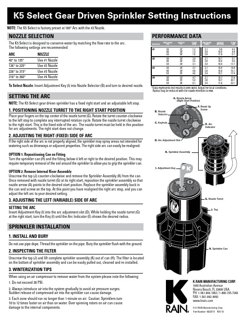
NOTE: The K5 Select is factory preset at 180° Arc with the #2 Nozzle.NOZZLE SELEcTiONThe K5 Select is designed to conserve water by matching the flow rate to the arc.The following settings are recommended:Arc NOZZLE40° to 135° Use #1 Nozzle136° to 225° Use #2 Nozzle226° to 315° Use #3 Nozzle316° to 360° Use #4 NozzleTo Select Nozzle: Insert Adjustment Key (I) into Nozzle Selector (B) and turn to desired nozzle. SETTiNG THE ArcNOTE: The K5 Select gear driven sprinkler has a fixed right start and an adjustable left stop. 1. POSiTiONiNG NOZZLE TurrET TO THE riGHT STArT POSiTiONPlace your fingers on the top center of the nozzle turret (G). Rotate the turret counter-clockwise to the left stop to complete any interrupted rotation cycle. Rotate the nozzle turret clockwise to the right start. This is the fixed side of the arc. The nozzle turret must be held in this position for arc adjustments. The right start does not change.2. AdjuSTiNG THE riGHT (FixEd) SidE OF ArcIf the right side of the arc is not properly aligned, the sprinkler may spray areas not intended for watering such as driveways or adjacent properties. The right side arc can easily be realigned.OPTiON 1: repositioning can on FittingTurn the sprinkler can (H) and the fitting below it left or right to the desired position. This may require temporary removal of the soil around the sprinkler to allow you to grip the sprinkler can.OPTiON 2: remove internal riser AssemblyUnscrew the top (J) counter-clockwise and remove the Sprinkler Assembly (K) from the can. Once removed with nozzle turret (G) at its right start, reposition the sprinkler assembly so that nozzle arrow (A) points to the desired start position. Replace the sprinkler assembly back in the can and screw on the top. At this point you have realigned the right arc stop, and you can adjust the left arc to your desired setting.3. AdjuSTiNG THE LEFT (VAriAbLE) SidE OF ArcSETTiNG THE ArcInsert Adjustment Key (I) into the arc adjustment slot (D). While holding the nozzle turret (G) at the right start, turn the Key (I) until the Arc Indicator (E) shows the desired radius.SPriNkLEr iNSTALLATiON1. iNSTALL ANd buryDo not use pipe dope. Thread the sprinkler on the pipe. Bury the sprinkler flush with the ground.2. iNSPEcTiNG THE FiLTErUnscrew the top (J) and lift complete sprinkler assembly (K) out of can (H). The filter is located on the bottom of sprinkler assembly and can be easily pulled out, cleaned and re-installed. 3. WiNTEriZATiON TiPSWhen using an air compressor to remove water from the system please note the following:1. Do not exceed 30 PSI.2. Always introduce air into the system gradually to avoid air pressure surges.Sudden release of compressed air into the sprinkler can cause damage.3. Each zone should run no longer than 1 minute on air. Caution: Sprinklers turn10 to 12 times faster on air than on water. Over spinning rotors on air can causedamage to the internal components.#1 30 32’ 1.240 34’ 1.350 36’ 1.6#2 30 33’ 2.440 34’ 2.550 34’ 3.1#3 30 34’ 3.740 34’ 4.050 35’ 4.6#4 30 33’ 4.740 35’ 5.350 36’ 6.12.1 9.8 4.52.8 10.4 4.93.4 11.0 6.12.1 10.1 9.12.8 10.4 9.53.4 10.4 11.72.1 10.4 14.02.8 10.4 15.13.4 10.7 17.42.1 10.1 17.82.8 10.7 20.13.4 11.0 23.1 *Data represents test results in zero wind. Adjust for local conditions.Radius may be reduced with the nozzle retention screw. PErFOrMANcE dATAA. Nozzle Arrow。
哈工大机械学基础课设——航空开伞器说明书全解

目录1.说明书正文 (1)1.1任务分析、方案确定 (1)1.2开伞器的用途 (1)1.3工作原理 (2)1.3.1 时控机构原理 (2)1.3.2 高控机构原理 (3)1.4开伞器时控机构设计 (4)1.4.1已知条件 (4)1.4.2三级升速齿轮设计 (4)1.4.3擒纵调速器工作原理及扇形齿轮转角的计算 (7)1.4.4制动块设计 (8)1.5开伞器高控机构设计 (9)1.5.1已知条件 (9)1.5.2膜盒组件设计 (10)1.5.3杆机构设计 (11)1.6机构调整方法 (12)2.改进意见 (12)3.心得体会 (13)参考文献 (14)1.说明书正文1.1任务分析、方案确定整个课程设计安排12个设计日,进度如下:1. 任务分析、理论计算、草图2.5日2. 总装配图、展开图设计7日3. 部件图、零件图设计1.5日4. 编写说明书1日5. 答辩1日故安排具体实施步骤如下:1. 结合机械学基础所学知识对航空开伞器对基本原理进行了解和分析;2. 进行初步理论计算,包括时控机构设计和高控机构设计,主要是齿轮设计、膜盒设计和制动块设计;3. 绘制装配图草图,主要绘制各级齿轮、轴和膜盒,注意其相对关系和投影关系;4. 根据绘制的草图的相对位置和投影关系,绘制总装配图、展开图;5. 由总装配图、展开图绘制部件图和零件图;6. 完成所有图纸绘制之后,进行检查和修改;7. 进行总结,撰写说明书。
1.2开伞器的用途开伞器是一种机械式短时间延时控制机构,也可实现高度控制,被广泛地应用于空投、救生等领域。
将开伞器装在空投的人或物体上,跳离飞机后,开伞器可以控制在一定时间和达到一定高度时自动将降落伞打开,以保证安全着落。
除此以外,开伞器也可以用来延时引爆,例如鱼雷的引爆。
1.3工作原理由以上功能分析可知,航空开伞器由高控结构、时控机构、能源机构三部分组成。
工作原理见图1-1:123456912航空开伞器工作原理图中各个部件分别为:1.钢索2.弹簧3.滑轮4.制动块5.扇形齿轮6.柱销7.杠杆1 8.杠杆2 9.膜盒组件 10.中心轮组件 11.过轮组件 12.擒纵轮组件 13.擒纵叉 14.惯性轮 15.软锁针1.3.1 时控机构原理开伞器使用前,先将钢索1拉出,使圆柱弹簧2压缩。
机械创新设计大赛作品说明书

机械创新设计大赛作品说明书
——(台阶式商品装卸机构)
设计目的:
由于从厢式货车上卸载货物或者往车上装载商品主要靠人工操作,需要多名操作人员,效率较低且耗费人工。
本机构基于联动的多个多杆机构,可以达到商品装载和卸载的目
商品
的。
载物叉1
载物叉2
图1.-1
如图1-1,载物叉1处于高位,车上人员将货物搬运到载物叉1上。
多杆机构简图如1-2所示:
图1-2
图中,多杆机构结构类似于契贝谢夫行走机器人结构,我们将这个机构倒过来使用,通过两连杆伸长端的运动规律使两载物叉产生水平和竖直方向的相对位移,正转时能将商品由高到低卸载,反转时可将低处商品运往高处。
图1-3
两叉在等高处进行载荷的接替
图1-4
完成接替,在下方安装相似结构,通过皮带传动联动,可使货物达到台阶式下降的效果。
运送至最下一级的载物叉后,由卸载装置将货物倒出,运动简图如图: 载物叉1 下一阶段机构的载物叉
载物叉2
图1-5
通过如图多杆机构使货物倾斜一定角度依靠重力滑下,载物台归位过程中凸轮推动推杆将货物推开为下一件货物挪出位置。
优势:
相对于传送带机构,因为每一级都是水平抬放,无需考虑物品的摩擦 货物
推杆 载物叉。
机械创新设计大赛作品说明书

机械创新设计大赛作品说明书
——(台阶式商品装卸机构)
设计目的:
由于从厢式货车上卸载货物或者往车上装载商品主要靠人工操作,需要多名操作人员,效率较低且耗费人工。
本机构基于联动的多个多杆机构,可以达到商品装载和卸载的目
的。
载物叉1
载物叉2
图1.-1
如图1-1,载物叉1处于高位,车上人员将货物搬运到载物叉1上。
多杆机构简图如1-2所示:
图1-2
图中,多杆机构结构类似于契贝谢夫行走机器人结构,我们将这个机构倒过来使用,通过两连杆伸长端的运动规律使两载物叉产生水平和竖直方向的相对位移,正转时能将商品由高到低卸载,反转时可将低处商品运往高处。
图1-3
两叉在等高处进行载荷的接替
图1-4
完成接替,在下方安装相似结构,通过皮带传动联动,可使货物达到台阶式下降的效果。
运送至最下一级的载物叉后,由卸载装置将货物倒出,运动简图如图: 载物叉1 下一阶段机构的载物叉
载物叉2
图1-5
通过如图多杆机构使货物倾斜一定角度依靠重力滑下,载物台归位过程中凸轮推动推杆将货物推开为下一件货物挪出位置。
优势:
相对于传送带机构,因为每一级都是水平抬放,无需考虑物品的摩擦 货物
推杆 载物叉。
创客大赛作品设计说明书
创客大赛作品设计说明书
参赛作品说明书格式规范
1.总体要求
主要包括下列内容:作品详细描述、作品实物或模型的照片、创新点采用word 2003及以上版本编排。
2.页面要求
A4页面。
页边距:上25mm,下25mm,左、右各20mm。
正文尽量采用小四号字体,标准字间距,单倍行间距。
不要设置页眉,页码位于页面底部居中。
3.作品描述
设计说明书介绍中可插入图片二维、三维(渲染图)、CAD图纸皆可,力求能完整表达作品设计特色,这一部分内容不可超过4页。
4.图表要求
设计说明书介绍中可插入图片二维、三维(渲染图)、CAD图纸皆可,力求能完整表达作品设计特色。
如有坐标图,则坐标图的横纵坐标应标注对应量的名称和符号/单位(并加题号,位于图下方)。
表格按序编号,并加表题(位于表上方)。
采用三线表,必要时可加辅助线。
机械原理课程设计雨伞

机械原理课程设计雨伞一、教学目标本节课的学习目标包括知识目标、技能目标和情感态度价值观目标。
知识目标要求学生掌握雨伞的基本结构和工作原理,了解机械原理在雨伞设计中的应用。
技能目标要求学生能够运用所学的机械原理,分析和解决实际问题。
情感态度价值观目标培养学生对机械工程的兴趣,提高学生创新意识和动手能力。
二、教学内容本节课的教学内容主要包括雨伞的结构、工作原理和机械原理的应用。
首先,介绍雨伞的基本结构,包括伞面、伞骨、手柄等部件。
然后,讲解雨伞的工作原理,如开合机制、承重原理等。
接着,引导学生了解机械原理在雨伞设计中的应用,如齿轮传动、杠杆原理等。
最后,通过案例分析,让学生学会运用机械原理解决实际问题。
三、教学方法为了提高教学效果,本节课采用多种教学方法。
首先,运用讲授法,清晰地讲解雨伞的结构、工作原理和机械原理的应用。
其次,采用讨论法,引导学生分组讨论,分享各自的见解和思考。
此外,运用案例分析法,让学生通过分析实际案例,掌握机械原理在雨伞设计中的应用。
最后,开展实验活动,让学生亲自动手,制作简易雨伞,增强实践操作能力。
四、教学资源为了支持教学内容的实施,本节课准备了一系列教学资源。
教材方面,选用《机械原理》一书,为学生提供理论知识的基础。
参考书方面,推荐《现代雨伞设计》等书籍,拓展学生视野。
多媒体资料方面,制作了雨伞结构和工作原理的PPT 演示文稿,以及相关视频资料,便于学生直观理解。
实验设备方面,准备了雨伞模型、齿轮传动装置等,为学生提供实践操作的机会。
五、教学评估本节课的评估方式包括平时表现、作业和考试三个部分。
平时表现主要评估学生在课堂上的参与程度、提问回答等情况,占总评的30%。
作业包括课堂练习和课后作业,占总评的40%。
考试为闭卷考试,占总评的30%。
评估方式客观、公正,全面反映学生的学习成果。
六、教学安排本节课的教学安排如下:共4课时,每课时45分钟。
第一课时介绍雨伞结构,第二课时讲解工作原理,第三课时分析机械原理应用,第四课时进行案例讨论和实验操作。
“全自动伸缩长柄伞”创新设计
荆楚理工学院《机械创新设计》课程论文学院:机械工程学院班级: 20机制一班学生姓名:冯灿学号: 2020203040102论文题目:“全自动伸缩长柄伞”创新设计完成日期: 2021 年 5 月 27 日指导教师评语:成绩:教师签名:作品内容摘要通过这个学期创新学课程的学习,我对创新学有了重新的认识,一开始以为创新学只是关于一些最基础的理论知识的讲解,但是经过老师的介绍,我才认识到创新就在我们的日常生活中,我们平时每个人都有很多的创新机会。
何为创新学?创新学是关于创新的本质和规律的科学,是关于创新的理论化系统化的世界观和方法论。
创新学研究的范畴很广,总的可概括为两大类创新,即生产力创新与劳动者创新。
在逐渐了解了创新的概念之后,老师又一点点的把我们带入了创新的殿堂,我深深的沉侵在“创新”之中,于是我真的开始思考日常生活中每次想到又没有勇气思考而被遗忘的那些小小的灵感。
Through the study of innovation course this semester, I had a new understanding of innovation learning. At the beginning, I thought that innovation learning was just an explanation of the most basic theoretical knowledge. However, only after the introduction of the teacher, I realized that innovation is in our daily life, and each of us had a lot of innovation opportunities. What is innovation science? Innovation science is the science about the nature and law of innovation, and it is about the theoretic and systematic world view and关键词:创新雨伞,方便出行目录关键词:创新雨伞,方便出行 (2)1.设计背景及意义 (4)2、创造原理 (4)3 设计过程 (4)3.1传动装置确定 (4)3.2工作过程及原理分析 (4)3.3开关的设置 (5)4 创新特色 (5)5 应用前景 (5)结束语 (6)参考文献 (6)1.设计背景及意义目前国内外对于自动伞的创新和设计有许多,如:半自动长柄伞、三折伞、五折伞。
新结构设计的飞行式伞身东方胡1说明书

The New Structural Design for Airborne PodDongfang Hu1, a*, Jianwei Guo1, b and Yan Zhao2, c1School of Mechatronics Engineering, Henan University of Science and Technology, Luoyang 471003,China2LandGlass Technology Co., Ltd, Luoyang 471003, Chinaa b cKeywords: Airborne pod; Horizontal shafting; Vertical shafting; Design systemAbstract. Airborne pod is mounted on helicopters or unmanned aerial vehicles. Its main structure tends to be influenced by many factors such as air flow, air temperature, foreign body, and the normal work of sensors may be interfered. However, a logical mechanical system‟s structure can effectively improve the imaging effect and improve the scanning accuracy. Thus, through systematically elaborate the arrangement of its control system, the theory for dividing horizontal shafting and vertical shafting, and the method for outputting completed 3D models and their supporting engineering drawings by UG platform, a composite structure of airborne pod is designed, which provides a preliminary design system for domestic new airborne pod structure.IntroductionThe pod adopts the axially symmetric structure to improve the overall strength of the pod, and build the “two axis and two frame” structure which realizes the operation on economy and high efficiency [1, 2].On the basis of the above given technical indicators, the design for pod body is divided into two part - the part of frames and the part of motion mechanism.The part of motion mechanism refers to the horizontal axis organization and the azimuth axis organization. The horizontal axis organization controls the cabin changing the pitch angle of the implementation, which achieves the pitching motion of the inner framework; the holder linked with the azimuth axis as a whole, is mainly used to achieve the azimuth rotation of the outer shell. The whole machine uses the upper part of the pod to link with the bottom plate of the plane [2]. The layout structure of the air-borne pod is as shown in Fig. 1.The Specific Layout Structure of Airborne PodThe Shaft Arrangement of the Airborne Pod. The horizontal axis and its drive system, arms of the holder and the main frame, are named as the horizontal shafting; meanwhile, the azimuth axis and its drive system, the upper arm of the holder, the upper body of the whole pod, are called as the azimuth shafting. Horizontal shaft design will be discussed in detailMoreover, the control system of scanning objects and the control system of internal environment are designed to improve the safe operation of the system, we adopt the frame structure of symmetry which could make the pod‟s the center of gravity and its geo metric center overlap together, this structure will greatly limit the impact resistance from flying posture and reduce from the perspective of the difficulty of adjustment [3, 4].The Main Framework Design of the Airborne Pod. Taking into account that kinds of internal photoelectric instruments need avoid the influence of temperature [5, 6], we design a kind of servo system concluding temperature compensation and motion control, its specific layout is as shown in Fig.2.ozimuth oxis systemshock obsocherholdermain fronehorizontol oxis systeminfrared imager and comeroFigure 1. The structural layout of the airborne podFigure 2. The servo system for thermal compensation and motion control.The Horizontal Shafting Structural Design of the PodThe selection of the motor is the key in the electric drive system. According to the design requirements: high speed, large torque, high running accuracy, and the working environment of low temperature, a Swiss series of cryogenic permanent magnet DC servo motor is our preliminary choice.The Components Selection and the Corresponding Load in the Horizontal Shafting.Tab According to the design requirements, the outer shell is designed as the structure which composed of the front shell and the back shell, and its diameter is 260mm.In addition, we have made ABS-GF shell material for the machine of the infrared imaging and visible light camera.All of the parts are divided into the two types-the mechanical parts and the electrical load Calculation of the moment of inertia, and the software UG was used after the assembly, the details as shown in Table 1.The Assembly Parameters of the Horizontal Drive Shaft. Simplify the problem to a reducer gear. The effective power of the horizontal shaft work as required.2.0415w v P F == (1)According to the mechanical design manual, the motor output power to meet the requirement [7].11232.1693wP P wηηη==⨯⨯ (2)Table 1 The inertia estimating form for the horizontal shaft‟s main partsCategoryItem Results of UG analysisshop sign quality/kg inertia/kg •m 2 Mechanical structuresealing material 5171 0.0018 2.5922×10⁻⁵ front shell ZL205A 0.4199 0.0048 back shell ZL205A 1.2972 0.0118 hot and cold temperature controller LHS_15 0.0813 0.0009 bearing frame ZL205A 0.3652 0.0014 vibration damper plate 2A12 0.1625 0.0002 Gear 1a, 1b 40CrA 0.2859 0.0007 spoiler motor MONO 0.1444 0.0008 angle measuring device M2500 0.1188 2.3196×10⁻⁵ other connections Alloy steel0.1994 0.0016 Electrical loadInfrared imager/ 0.7800 0.0041camera/0.4500According to the motor has been selected, the out-put power is 62w which is much higher than the actual needs of the power, so it can meet the requirements.m w n i n =(3)In the formula, i is the total transmission ratio, nm is the full speed reducer of the DC motor, and its value is 20.9790r/min. The output power of DC motor with gear output to the outer frame60==123.2033/min w ivn r d π (4)It is concluded: i=1.7191, due to its transmission is only one level, so the gear ratio is i01=1.719 The Design for the Shaft, Bearings, the Key of the Horizontal Shafting. Calculation criterion of shaft can be divided into strength checking and axial stiffness checking. When the shaft is used with high-speed rotation, the shaft vibration checking should be carried out.The Drive Shaft I . The shaft power P1=61.38w, n1=20.9790r/min, the torque T1 is 27.9412N·m. The force on the shaft of the gear 1a.3112227.9412101117.648N50t T F d ⨯⨯=== (5)tan 1117.648tan 20406.791N r t F F α==⨯︒= (6)1117.6481189.376N cos cos 20t n F F α===︒ (7)According to the technical parameters given by enterprises, to determine the minimum diameter ofthe initial axis, selected the shaft material is 40Cr which makes the quenching and tempering treatment.Taking A0=97, then giving the following data.min 0970.143013.8735mm d A ==⨯= (8) The minimum diameter of the shaft is in accordance with the diameter of the shaft coupling mechanism to select. In this design, we use four connecting bolts install the pitch-drive motor at the inner frame, and the motor shaft and gear 1a are be fixed as a whole by the small key. The inner six angle screw bolt is arranged in the hole of the convex side of the gear 1a, it presses the key to prevent small loose. The gear 1a and the motor shaft directly use a flat wedge key to position their location; the motor shaft diameter is 14mm. the data of motor diameter can be checked the key width b and the key height, it is 5×5mm. the key length L is 16mm.In order to improve the running reliability of the system, a set screw. At the same time, in order to ensure the gear with the shaft of the motor having a good selection of neutral, the gear wheel and the shaft of the motor should put to use H7/n6.For the axial force analysis and the calculation of bending moment, considering the paper has said, we simplify the problem as the sake of cantilever beam bending moment and shear force. Among them, the distance between the sustain device of the motor and the gear center is L1=8mm.111117.648N t NH F L F L ⋅== (9) 11406.791N r NV F L F L ⋅==(10) 1189.376N N F == (11)11117.6480.0088.941N m NH NH M F L =⋅=⨯=⋅ (12)1406.7910.008 3.254N m NV NV M F L =⋅=⨯=⋅(13)9.515N m M ==⋅ (14)127.9412N m T T ==⋅ (15)The result, σ p =99.79MPa.Checking tables [σ P ] =100~120MPa, clearly meet the requirements. Strength check of shaft.According to the checking of bending and torsional strength calculation, we check the root section of the axis of maximum bending moment and torsion shaft.ca σ32(d t)322d bt W dπ-=-(17) The shaft is unidirectional rotation, torsion shear stress is pulsating cyclic stress, α=0.6.[]158.2496MPa ca σσ-=< (18)The shaft‟s strength meets the design standards.According to the calculation of the shaft stiffness checking, we focused on the end of the shaft mounted gear 1a as the study object, the cantilever beam deflection and angle formula.2(3)6Fx w l x EI -=- (19)22Fl EI θ-=(20)According to the known data, FN=1189.376N, the elastic modulus of 40Cr was E=210GPa,I=πd4/64, When the “x” is l, we get these result: w=5.1259×10⁻¹⁰<<0.002l, θ=9.6110×10⁻¹¹<<0.001.The Drive Shaft II (the Fixed Mandrel). The pod is designed for symmetry, in the analysis of II transmission shaft, the drive shaft support focus on the side of the detailed analysis and calculation, the assumption that the shaft is a drive shaft, the shaft power is P2=59.5386w, n2=12.2042r/min, the torque is T2=46.5900N·m. The minimum diameter of the initial axis, according to the technical parameters given by enterprises, selection of shaft material is 40Cr, quenching and tempering treatment. A0=97.min 0970.169616.4512mm d A =⨯= (21) SummaryThe pod is adopted the symmetric structure. Meanwhile, the …two axes and two frames ‟ structure is proposed.Introducing the design idea of the airborne pod structure, which provides strong evidence for the feasibility of pod.The mechanism of control system is designed and operated from the aspects of control theory; the possible problems in the pod structure design had been made a detailed analysis.Through the design of horizontal shaft system, and the calculation of each component‟s material selection, the whole structure design is completed by using UG solid modeling.Due to the use of UG drawing module, the 3D design could directly switch into the 2D pictures used as figures, which greatly simplifies the design process and provide the safeguard for the manufacturing process. AcknowledgementsThe authors gratefully acknowledge the National Nature Science Foundation (Project No. 51575160), the Key Technology R &D Program of Henan Province (Project No. 13A520232), and the Major and previous pre-research project of Henan University of Science and Technology (Project No. 2011CX016).References[1] H.L. Ma: The structural design research and finite element analysis on two gimbals and two axisopto-electronic platform (MS., Jilin University, China 2011), p.3 (In Chinese).[2] L.B. Wang: The application and research of con-trol system for airborne optoelectronic pod (MS.,Henan University of Science and Technology, China 2011), p.2 (In Chinese).[3] Y.F. Shen, P.Y. Zhao, and Z.J. Chen: Aero Weaponry, (2010) No.3, p.61 (In Chinese).[4] M. Zhang, W.B. Liu, and C. Li: Acta Aeronautica ET Astronautica Sinica, Vol. 43 (2015) No.3,p.857 (In Chinese).[5] Y.P. Qu: Acta Aeronautica et Astro-nautica Sinica, Vol. 35 (2014) No.8 p.2307 (In Chinese).[6] J.Z. Yu, N. Su: Acta Aeronautica ET Astro-nautica Sinica, Vol. 21 (2000) No.5 p.399 (InChinese).[7] The editorial board for the handbook of me-chanical design: Machinerys Handbook. (ChinaMachine Press, Beijing, 2004) (In Chinese).。
- 1、下载文档前请自行甄别文档内容的完整性,平台不提供额外的编辑、内容补充、找答案等附加服务。
- 2、"仅部分预览"的文档,不可在线预览部分如存在完整性等问题,可反馈申请退款(可完整预览的文档不适用该条件!)。
- 3、如文档侵犯您的权益,请联系客服反馈,我们会尽快为您处理(人工客服工作时间:9:00-18:30)。
机械创新设计说明书设计题目:班级:学号:姓名:指导教师:2014年 12 月 11 日目录摘要 (1)1、选题背景 (2)2、设计条件与要求 (3)3、原理方案设计 (4)4、总体结构设计………………………………………………………5、详细设计……………………………………………………………6、设计总结……………………………………………………………参考文献…………………………………………………………摘要本设计属于生活用品技术领域,设计为一种偏心伞。
市面上广泛出售的伞一般为中心支撑类型,稍微改进的是将伞叶的形状进行调整,个别偏心伞使用环境过于单一,造成使用不方便。
如中国实用新型公开了一种偏心伞,该偏心伞能够调节偏心的距离,它包括由伞面、伞面撑骨、联接盘和伞杆等构成,该偏心伞打开时即为偏心结构,在不需要偏心功能时无法像普通雨伞一样使用,同时其偏心距离也无法调节。
本实用新型的目的是针对现有的技术存在上述问题,提出了一种偏心伞,该偏心伞能够调节偏心的距离,使用更加方便,本设计是在伞把与伞面结合的下端设计一个可调节的自由端,该部分由两个活动杆连接伞把,使之可以自由调节,实现多用途,多选择等功能,让伞的使用更加方便。
1、选题背景伞是一种提供阴凉环境或遮蔽雨、雪的工具,伞的制作材料通常包括了具延展性的布料,和其他可用作骨架的材料与缠线。
使用时以手将之举起,虽然伞在最初发明时的主要目的,是用来阻挡阳光,但是现在最常被当作雨天挡雨的工具。
伞种类繁多,包括油纸伞、透明伞、太阳伞等,其伞面呈圆形,在伞面下方中心位置连接有手柄,手柄与伞面之间有连接着支伞骨,通过支伞骨实现伞面撑开与收拢。
在雨伞的长时间使用过程中,人们又设计出了雨伞新的功能,如偏心伞。
由于雨伞在使用时是通过一只手握持,因此雨伞的中心位置靠近身体的一侧,使得伞面靠向一侧,另一侧容易淋到,如果将雨伞倾斜握持,使用较为费力,而偏心伞针对上述问题,能够在单手握持时使雨伞中心位置位于人的正上方。
如中国实用新型公开了一种偏心伞,它包括由伞面、伞面撑骨、联接盘和伞杆等构成,其特征在于所述的伞面由主伞面和副伞面构成,为非对称结构,所述的伞杆结合于主伞面的中心位置,主伞面为圆形结构,副伞面为椭圆形结构,整个伞面由圆形与椭圆形交集构成,与已有技术相比具有适合用于双人使用,荷载较为均匀的优点。
但是该偏心伞打开时即为偏心结构,在不需要偏心功能时无法像普通雨伞一样使用,同时其偏心距离也无法调节。
本实用新型的目的是针对现有的技术存在上述问题,提出了一种偏心伞,该偏心伞能够调节偏心的距离,使用更加方便。
1、设计目的与要求2.1设计目的偏心伞是从“以人为本“、”关爱“的仁爱思想为出发点,发明创新的新型伞。
偏心伞是将传统伞的中心对称结构用交叉支撑的杠杆原理,将伞杆向一根伞骨上进行位移,使位于中心位置的伞杆偏于侧面,形成了非对称的伞体结构的新型伞。
偏心伞的特殊结构明显增大了持伞人的有效遮雨面积,从而偏心伞比传统伞更加实用。
2.2设计要求该设计属于在原有生活使用工具的基础上进行改进与创新,属于小型设计,时间要求不是特别长,设计所需的技术、经费、设备和其他一些条件等要求均不是特别高。
本设计涉及结构力学和材料力学以及一些物理方面等知识。
该设计需要解决自由端的受力情况分析、形状的设计、杆与杆之间的连接、连接端的可调控制装置,材料的选取等多项问题。
3、原理方案设计设计偏心伞要求结构简单,经济适用,价格低廉。
3.1功能分析根据偏心伞的结构特性,我们可以详细分析出它的功能,如下所示:遮阳伸拉调整开伞挡雨伸拉调整3.2 工作原理分析此偏心伞利用四杆连杆机构的运动角度来决定伞的偏移距离,从而找出最佳的遮挡位置再加以固定。
开伞及调节角度方式用手动式,以此设计可以节约成本,也可以起到节能环保的作用。
现以手动方式进行下列分析。
3.3 功能分解动力(手动)运动变换偏心伞连杆运动运动调节收缩双向调整3.4 功能求解3.5 方案组合可能组合方案数N 为N =3×3×3×3=51经过分析列出3种方案进行比较:方案A:往复移动(1A) 齿条(2B) 卡条(1D)方案B:往复摆动(2A)连杆(2C)锁紧螺栓(2D)方案C:往复摆动(2A)扇形齿轮(1C)锁紧螺栓(2D)3.6 利用FD法求解加权系数通过对影响偏心伞总体性能、结构性和使用寿命等很多因素进行重要程度比较,我们选择的平价目标有:价格、遮挡面积、抗风能力、外观、维修性,我们使用10分发对各个评价目标按重要影响程度分别给出相应的分值。
加权系数判别表3.7 评价目标树3.8 采用评分法评价方案并选取最优方案(1)三种方案综合评分(2)按加权计分法求各方案总分332211g A A A A p g P g P N ++==0.52×7+0.38×7+0.1×5 =6.8332211g B B B B p g P g P N ++==0.52×9+0.38×8+0.10×5 =8.22332211g C C C C p g P g P N ++==0.52×6+0.38×7+0.10×5 =6.28因为B N >A N >C N ,所以选择方案B 为最佳方案。
4、总体结构设计本实用新型的目的可通过下列技术方案来实现:可调节式偏心伞,包括伞面和一端连接在伞面上的支撑杆,伞面与支撑杆之间连接有支伞骨,其特征在于,还包括呈杆状的手柄、连杆一和连杆二,连杆一的一端转动连接在支撑杆的自由端端部,另一端转动连接在手柄上,连杆二的一端转动连接在手柄的端部,另一端转动连接在支撑杆上,连杆一与连杆二相平行且长度相等,连杆一与手柄之间设有能够将连杆一固定在手柄上的定位件。
支伞骨的一端均铰接在伞面上,另一端均铰接在一个套环上,套环套在支撑杆上,能够沿着支撑杆移动,实现伞面的撑开与收拢;连杆一与连杆二之间具有距离,且相互平行,支撑杆与手柄相互平行,因此连杆一、连杆二、手柄及支撑杆之间形成四连杆结构,通过该四连杆能够调节支撑杆与手柄之间的水平距离,在调节到合适位置后通过定位件固定住,因此使用更加方便。
连杆一的长度大于连杆一与手柄铰接点到手柄端部的距离,连杆二的长度大于连杆二与支撑杆铰接点到支撑杆自由端端部的距离。
即定位件松开时手柄能够移动到支撑杆的正下方,支撑杆与手柄同轴,此时该偏心伞与普通的雨伞无异。
所述定位件包括一锁紧螺栓,所述连杆一的端部径向开设有连接孔,所述手柄上径向开设有螺孔,所述锁紧螺栓穿过连接孔螺旋连接在螺孔内。
通过锁紧螺栓来实现固定,结果简单、操作方便。
所述手柄连接端端面上轴向开设有一盲孔,所述盲孔内设有弹簧和插接柱,所述弹簧的一端抵压在盲孔底面上,另一端抵压在插接柱端面上,所述支撑杆自由端端面上轴向开设有插接孔,当支撑杆与手柄轴向对齐时,所述插接柱插入插接孔。
当手柄移动到支撑杆的正下方时,插接柱插入插接孔,插接柱能够增强支撑杆与手柄之间的连接强度,且保证同轴度。
所述盲孔内壁沿轴向方向开设有贯穿的条形槽,所述插接柱侧面上垂直具有一推销,所述推销伸出条形槽。
推销用于控制插接柱,通过推销能够使插接柱缩入盲孔。
所述支撑杆与手柄均为圆杆,且支撑杆与手柄的直径相等。
直径相同,连杆一与连杆二的侧面同时抵靠在支撑杆与手柄的外侧面上,结构匀称、紧凑。
所述锁紧螺栓的头部具有旋钮。
方便施力旋转锁紧螺栓,操作方便。
5、详细设计以下是本实用新型的具体实施例并结合附图,对本实用新型的技术方案作进一步的描述,但本实用新型并不限于这些实施例。
如图 1、图 2、图 3 所示,一种偏心伞,包括伞面 1 和支撑杆 3,支撑杆 3 的一端连接在伞面 1 的中心位置,伞面 1 与支撑杆 3 之间连接有支伞骨 2,支伞骨 2 的一端均铰接在伞面 1 上,另一端均铰接在一个套环上,套环套在支撑杆 3 上,能够沿着支撑杆 3 移动,实现伞面 1 的撑开与收拢。
偏心伞还包括呈杆状的手柄4、连杆一 5 和连杆二 6,连杆一 5 的一端转动连接在支撑杆 3 的自由端端部,另一端转动连接在手柄 4 上,连杆二 6 的一端转动连接在手柄 4 的端部,另一端转动连接在支撑杆 3 上,连杆一 5 与连杆二 6 相平行且长度相等,两者之间具有距离,支撑杆 3 与手柄4 相互平行,因此连杆一 5、连杆二 6、手柄 4 及支撑杆 3之间形成四连杆结构,通过该四连杆能够调节支撑杆 3 与手柄 4 之间的水平距离,连杆一 5与手柄 4 之间设有能够连杆一 5 固定在手柄 4 上的定位件,在手柄 4 位置调节合适后通过定位件固定住,因此使用更加方便。
图1图2图3具体来说,结合图 4、图 5 所示,连杆一 5 的长度大于连杆一 5 与手柄 4 铰接点到手柄 4 端部的距离,连杆二 6 的长度大于连杆二 6 与支撑杆 3 铰接点到支撑杆 3 自由端端部的距离,即定位件松开时手柄 4 能够移动到支撑杆 3 的正下方,支撑杆 3 与手柄 4 同轴,此时该偏心伞与普通的雨伞无异。
支撑杆 3 与手柄 4 均为圆杆,且支撑杆 3 与手柄 4 的直径相等,连杆一 5 与连杆二 6 的侧面同时抵靠在支撑杆 3 与手柄 4 的外侧面上,结构匀称、紧凑。
定位件包括一锁紧螺栓 7,连杆一 5 的端部径向开设有连接孔,手柄 4 上径向开设有螺孔,锁紧螺栓 7 穿设连接孔与螺孔将连杆一 5 固定在手柄 4 上,通过锁紧螺栓 7 来实现固定,结果简单、操作方便。
锁紧螺栓 7 的头部具有旋钮 71,方便施力旋转锁紧螺栓 7,操作方便。
手柄 4 连接端端面上轴向开设有一盲孔 41,盲孔 41 内设有弹簧 42 和插接柱 43,弹簧 42 的一端抵压在盲孔 41 底面上,另一端抵压在插接柱 43 端面上,支撑杆 3 自由端端面上轴向开设有插接孔 31,当支撑杆 3 与手柄 4 轴向对齐时,插接柱 43 插入插接孔 31,插接柱 43 能够增强支撑杆 3 与手柄 4 之间的连接强度,且保证同轴度。
盲孔 41 内壁沿轴向方向开设有贯穿的条形槽411,插接柱 43 侧面上垂直具有一推销 431,推销 431 伸出条形槽411,推销 431 用于控制插接柱 43,通过推销 431 能够使插接柱 43 缩入盲孔 41 中。
图4图55、设计总结与现有技术相比,本偏心伞具有以下优点:1、由于连杆一、连杆二、手柄及支撑杆之间形成四连杆结构,通过该四连杆能够调节支撑杆与手柄之间的水平距离,在调节到合适位置后通过定位件固定住,因此使用更加方便。
2、由于手柄能够移动到支撑杆正下方,支撑杆与手柄同轴,因此该偏心伞能够达到与普通的雨伞一样的状态,使用状态多样。