风扇寿命计算方式
如何测试风扇的寿命

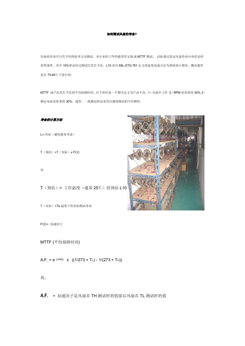
如何测试风扇的寿命?风扇的寿命可以有不同的技术方法测试。
本行业的工作师通常用L10或MTTF测试。
L10通过设定风扇寿命分布状态的某种条件,其中10%样品经过测试后发生不良。
L10是以MIL-STD-781定义的温度加速方法为基础来计算的。
测试通常是在70-80℃下进行的。
MTTF 或产品发生不良的平均故障时间。
以下的任意一个都可定义为产品不良:1)风扇不工作2)RPM是原来的30%3)额定电流是原来的30%。
通常,一批测试样品是用以确保测试的可信赖性。
寿命的计算方法L10寿命(最短服务寿命)T(预估)=T(实际)x FCC而T(预估)= 工作温度(通常25℃)的预估L10T(实际)=Ta温度下的实际测试寿命FCC=加速因子MTTF (平均故障时间)A.F. = e (DH/K) x ((1/273 + TL) - 1/(273 + TH))A.F. = 加速因子是风扇在TH测试时的值除以风扇在TL测试时的值273 = 绝对温度e = 自然logDH = =激活能量K = Bottzmann's 恒量= 8.623x10⁻⁵TL = 低温测试= 50oCTH = 高温测试= 80oC寿命特性取决于电压,频率,环境温度,装配状况,和某种单个用途对风量要求的综合因素。
然而,决定寿命失败的关键性因素是轴承和轴承的润滑油。
轴承种类轴承与风扇之间是直接的关系。
如轴承运行中断,风扇也将中断运行。
有多种不同的轴承可供考虑。
分别有含油的,滚珠/含油,滚珠轴承。
寿命随着轴承类型从左往右移动而增加。
含油轴承相对于滚珠轴承在初如运转时更安静。
对于滚珠轴承,在极高的温度下运行状态会更好。
含油轴承的寿命大约为30,000小时或为正常状态下,即每天工作8小时,能使用6年。
刚开始有提到,含油轴承风扇比滚珠轴承风扇更安静。
然而,随着时间的推移,含油轴承会开始失去润滑并会相反的发出更大的噪音。
滚珠轴承风扇的寿命稍微有些不同。
风扇寿命计算方式

1 /2 ※風扇壽命計算方式依固定時間及固定數量在固定測試時間結束後,分別用高溫及低溫下產生的失效故障風扇數量,再依加速模式去推估風扇的壽命。
※公式參數的意義及計算方式A.F =e ⎪⎭⎫ ⎝⎛K ∆H ⎪⎭⎫ ⎝⎛+-+Th Tl 27312731A.F : 加速因子(倍數)△ H: 活化能K(波氏常數)=8.623×10⁻⁵TL: 測試時低溫溫度TH: 測試時高溫溫度․△H 之計算若烤箱#1之故障數為r1,烤箱#2之故障數為r2,則r1/r2=e ⎪⎭⎫ ⎝⎛K ∆H ⎪⎭⎫ ⎝⎛+-+Th Tl 27312731-------------------------(1)式∵r1、r2已知,e(自然對數)=2.713….,K(波氏常數)=8.623×10⁻⁵, TL ,TH 代入(1)式 △H 即可求得。
將△H 、Tl =30、40、50、60、70及分別代入(2)式, A.F =e ⎪⎭⎫ ⎝⎛K ∆H ⎪⎭⎫ ⎝⎛+-+Th Tl 27312731-------------------------(2)式可得到30、40、50、60℃對70℃之加速倍數。
․70℃ 90﹪信賴水準MTTF 值之計算先算出總試驗時間T=(100–r)×試驗時數+r1+r2+r3……..*註:r 代表烤箱#1之總故障數,r1、r2、r3……分別代表烤箱#1之第一個故障時間、第二個故障時間、第三個故障時間…。
當r=0時,M=2.3026 ,r=1時,M=3.8897,……如下表GEM TABLE 在90﹪信賴水準所以70℃90﹪信賴水準MTTF =T/r,r以GEM TABLE之M值代入求得。
․L10 計算方式:將各溫度MTTF值除以2.445係數即得之。
․λ(故障率):單位時間內可能故障的機率λ= 1除以各溫度MTTF值․以上加速壽命試驗方式依美軍MIL-HDBK-781規範。
友情提示:方案范本是经验性极强的领域,本范文无法思考和涵盖全面,供参考!最好找专业人士起草或审核后使用。
DC风扇知识培训教材

十位有效数 0 1 2 3 4 5 6 7 8
9
第八章 风扇常使用的电子零件
232
个位有效数 0 1 2 3 4 5 6 7 8
9
倍率数 1Ω 10Ω
100Ω 1KΩ 10 KΩ 100 KΩ 1MΩ 10MΩ
50C
字母 A 倍率 1
B
C
D
E
X
F
10 100 1000 1000 -10 -100
第四章 DC风扇的电气特性
1. 额定电压: 风扇正常运转所需要的固定电压.(伏特:V) 2. 电压使用范围: 风扇能正常运转的电压范围. 3. 起动电压: 规定一额定电压(低电压),插上电源让风扇通电检测是否运转.(伏特:V) 4. 额定电流: 在风扇正常运转(额定电压条件下)时最高的电流.(安培:A) 5. 额定功率: 在额定电压与额定电流下的功率.(瓦特:W): 计算公式:W=I*V(功率=电流*电压) 6. 转速: 在环境25度,湿度百分之65以下,开机运转测试的运转转速.(转/每分:RPM) 7. 运转方向: 风扇扇叶的运转方向(逆时针或顺时针方向). 8. 风流方向: 风扇运转时出风的方向. 9. 风压和风量: 风压就是风的压力[mm/H2O(inch/H2O),风压水柱多少毫米(英 寸)];
第七章 DC风扇的常见不良原因与分析
5. 碰桌: 5.1. 扇叶变形 5.2. 磁浮调整不佳 5.3. 磁性不良 5.4. 组立末压到位(装配尺寸不佳)
6. 低电流(在规格电压下): 6.1. 线圈断线 6.2. 阻抗值高(低)于允差范围 6.3. 导线焊反或插错电源 6.4. 零件点空焊
7. 高电流:(在规格电压下): 7.1. 阻抗值偏见小 7.2. PC板短路,线圈线匝短路 7.3. 磁性不良 7.4. 培林与合铜不同心
培林(滚珠轴承)的寿命计算
条件 培林型号 MR52BT12CZZ MC3ERP5 NS7C Fr : 扇叶重量 0.01kg Fa : 予圧 0.15kgf 5,000rpm n : 风扇转数 5,000rpm Rating( C : Basic Dynamic Load Rating(参照弊司的商品目录) 19kgf Rating( 6kgf Co : Basic Static Load Rating(参照弊司的商品目录) 跳到商品目录一页! 跳到商品目录一页 (1) 求Co/Fa的值。 Co/Fa= 6/0.15=40 (2) 由Co/Fa的値根据前一页的表1可以求出e的值。 可以求出 Co/Fa値 由(1) 項进行計算所得出的Co/Fa的値, 如果与表1的Co/Fa値一致、 求出e 将很容易求出e的值, 但是大部分的情况下都需要进行以下计算. 0.23, 丛表1来看Co/Fa为30的时候, e为0.23,Co/Fa为50的时候e为0.20. 在这种时候从30 50之间的 30至 之间的e 可以认为是以一定比率进行变动, 在这种时候从30至50之间的e的值, 可以认为是以一定比率进行变动, 计算如下. e=0.23-((0.23-0.20)/(50-30))×(50-40)=0.215 e=0.23-((0.23-0.20)/(50-30))×(50-
资料1 商品目录(复印件) 资料1 商品目录(复印件)
资料2 扩大) 资料2 商品目录(扩大)
返回寿命计算
N
: 培林的容许转数 商品目录有记载。请使用下值。 ・商品目录有记载。请使用下值。 ① 681XZZ 100,000rpm ② MR52BZZ 85,000rpm ③ 693T12AZZ,693A3T12ZZ 60,000rpm 除上記3种型号以外,如果有需要的话请向我司咨询. ※ 除上記3种型号以外,如果有需要的话请向我司咨询.
电机风摩损耗计算
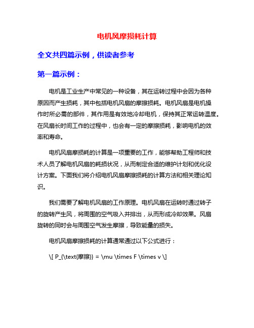
电机风摩损耗计算全文共四篇示例,供读者参考第一篇示例:电机是工业生产中常见的一种设备,其在运转过程中会因为各种原因而产生损耗,其中包括电机风扇的摩擦损耗。
电机风扇是电机操作时所必需的部件,其作用是有效地冷却电机,保持其正常运转温度。
在风扇长时间工作的过程中,也会有一定的摩擦损耗,影响电机的效率和寿命。
电机风扇摩损耗的计算是一项重要的工作,能够帮助工程师和技术人员了解电机风扇的耗损状况,从而制定合适的维护计划和优化设计方案。
下面我们将介绍电机风扇摩擦损耗的计算方法和相关理论知识。
我们需要了解电机风扇的工作原理。
电机风扇在运转时通过转子的旋转产生风,将周围的空气吸入并排出,从而形成冷却效果。
风扇旋转的同时会与周围空气发生摩擦,导致能量的损失。
电机风扇摩擦损耗的计算通常通过以下公式进行:\[ P_{\text{摩擦}} = \mu \times F \times v \]\( P_{\text{摩擦}} \)是风扇的摩擦损耗功率,单位为瓦特(W);\( \mu \)是空气的摩擦系数;\( F \)是风扇叶片的受力;\( v \)是风扇的旋转速度。
空气的摩擦系数\( \mu \)是一个常数,通常在标准条件下为0.02左右。
风扇叶片的受力\( F \)可以通过力学原理计算得出,其与叶片的几何形状和旋转速度有关。
风扇的旋转速度\( v \)通常由电机的工作参数确定。
在实际计算中,为了准确考虑电机风扇摩擦损耗的影响,我们还需要考虑一些其他因素,如环境温度、空气密度等。
这些因素会对摩擦系数和叶片受力产生影响,需要进行修正计算。
电机风扇摩擦损耗的计算对于电机的性能优化和维护具有重要意义。
通过了解风扇的摩擦损耗情况,可以及时作出调整和改进,提高电机的工作效率和寿命。
定期检测和计算摩擦损耗也有助于及时发现风扇故障,减少不必要的维修成本和停机时间。
电机风扇摩擦损耗的计算是电机维护和优化的重要环节。
通过合理计算和分析摩擦损耗情况,可以有效提高电机的运行效率和稳定性,延长其使用寿命,降低维护成本,实现更高效的生产和运作。
风扇寿命表格FS1240-A3012A---MTTF

Model No.Test Condition Input Voltage12VDC Electrical SpecificationSpeed 4000 RPM Test Temp.70℃Current0.09AmpDirection Vertical 43,429Hours Bearing System Start Date 8/2'084,576HoursTest Sample (pcs)Finish Date11/3'08Test Hours/Each Over2000Total Test HoursAccu. F/OTTF(Hours)UUT(pcs)Accu. F/RMTTF Test ResultAF :Acceleration factor for calculating MTTF at different temperature.(MIL-STD-781C) AF=2^﹝(Ta – Tu) / 10﹞Ta :Test temperature , Tu :Reference temperature MTTF = m L1 X AFThe following produre explains the derivation of L10Point estimates, confidence intervals, prediction intervals and tolerance intervalsm L1: Lower one-sided limit for the mean time to failure (MTTF)m L1 =1-α: Confidence Level (90%)T*:The accumulated test timer: Number of Failure(2r+2): Degree of FreedomX 21-α(2r+2):Tables of the fractiles of the χ2 distributionThe (L10)L1 at a lower one-sided 90﹪ confidence on MTTF is (L10)L1 = 【-ln (0.9)】X m L1Temp(℃).30℃40℃50℃55℃60℃63℃70℃MTTF 694,864347,432173,716130,28786,85870,55043,429L1073,21136,60518,30313,7279,1517,4334,576Calculation Refer To: IEC 60605-4:2001, EQUIPMENT RELIABILITY TESTING – Part 4:Statistical procedures for REV:A013. Fan not runexponential distribution – Point estimates, confidence intervals, prediction intervals and tolerance intervals.100000Total Test Hours =50 X 2000 = 100000HoursGet MTTF at 70℃Get L10 at 70℃The Estimated MTTF =100000 / 2.3026=43429Hours(IEC-60605-4:2001 section 5.1)ACT-RX Technology Corporation CeraDyna A50FS1240-A3012A Number of Failure Confidence Level 090﹪Failure CriteriaRemark: other competitors failure criteria - 30%Check point at the hours of 0, 250, 500, 750,1000,1500,2000…Test Result: (TTF: Time To Failure; UUT: Unit Under Test; F/R: Failure Rate, Datum, Stastics…etc.)Failure mode2. Current: Over 15% of original value 1. Speed: Under 15% of original value 2T*2T*χ21-α(2r+2)。
Fan noise-风扇的寿命,噪声计算

My first home PC, an 8086 clone, only had one fan (in the power supply) but it was NOISY. I used a very quiet 286 at work, so hoped things could be improved. After under-volting the fan with a couple of diodes and opening up the psu inlet grille, things were very much improved.These pages are intended as guidance for anyone else who wants to calm down their PC fans. I'm aiming at users who have a smattering of electrical/electronic knowledge, who can use a soldering iron, and who don't mind doing the work themselves rather than buying a solution.I also live in the UK, so suppliers and costs are UK-based where applicable. Noise from Case FansThe chart shows how much (or little) noise various fans make. All the data has been culled from the manufacturers' specs. and is for the common 80mm square x 25mm deep 12-volt units.One obvious feature is thatnoise goes up with fan flowrating. If you want a gale, itwill howl!Secondly, comparing likeflow rates, there's not allthat much differencebetween different brands,though Papst do come outas consistently quieter thanthe rest across the fullrange. (As they also cost upto 4 times as much as theothers it's good to see somejustification.) And YS-Tech'sreputation as noisy lookswell-deserved.Fans with sleeve bearingsare lower-noise than acomparable ball-bearing fanbut one common penalty isa shorter service life,though the better-qualitysintered metal sleeves, likePapst's Sintec® bearings,don't suffer this drawback. Another important point is that the noise figure you see quoted is measuredwith the fan suspended in the middle of an empty chamber; the noise you actually hear is with the fan fastened to a metal box, a grille of sorts on one end, and various cables and components in the flow path.This always increases the fan's noise level, sometimes more than doubling the perceived effect. Try removing a noisy fan from your case and running it hand-held – the difference may surprise you! But you can take steps to reduce this added noise back towards the "ideal" level, using the methods to be described. Finally, I've not found any genuinely "low-noise" fan designs available, onlylow-flow fans, quiet by virtue of the low output alone. By that I mean no maker produces a "low-noise" model with the same flow as their "standard" model. State of the art is such that the main difference between a cheap generic fan and a more expensive one is quality – better bearings, better finished mouldings, which have a minor impact on as-new noise levels but may well help keep the level consistent for longer.SolutionsSo, what does the seekerafter a quiet system do?Go for the minimumflow rate that'ssatisfactory, with theminimum number offans. Aim for a safecpu temperature thatgives stableoperation – there'sno need to go anycooler.Keep the floweffective with a cleanpath through thecase – a good casedesign, open wiregrilles, rounded drivecables, cables tiedout of the way, allhelp. Quite low levelsof case resistance willcut the quoted "freeair" flow by half withslow, low-flow fans.(more on backpressure)Reduce the noisefrom a stock fan byreducing its power.Another similaritybetween all the fansI've seen is that the air flow is closely proportional to the motor speed.It's no scientific law, just that all designers are after maximumefficiency and have come up with similar solutions.What is science is that the speed of a DC motor is proportional to it'svoltage, so by cutting the voltage you cut the speed so cut the noise ina forecastable fashion, as the graphs (right) show.The psu fan can also be replaced with a lower flow/noise model. 24cfm is about the minimum for a basic system (one hard drive, a CDdrive, not overclocked) but the quietest psus get round overheatingunder stress with temperature-controlled fan speed.Mount the fans so vibration isn't transmitted and amplified by the casepanels. Rubber grommets are a favourite method but involve somedrilling. Nylon nuts and bolts, rubber washers or adhesive foamdraught-excluder strip also work to a lesser extent.Keep a close eye on system temperatures for a few days, and don'tforget, the end result has to be a compromise between peace andcooling.More on Reducing Fan VoltageFirst find the flow for the fan concerned. If you also know the noisespec. you can fit it on the noise/flow chart above, if not assume mid-range.Then imagine a line between the extremes shown down to the noiselevel you fancy. 25dBA is fairly quiet, 20dbA very quiet, below 15dBAdamn near silent.Read off the flow at that noise level. Then the ratio of that flow to theflow at 12 volts will be approximately the same as the ratio of thevoltage needed to 12.For example, a fan outputs 37cfm with 12 volts. Noise is quoted at 30dBA, and you want 20dBA. Following the chart, flow at that noise level will be about 24 cfm.So 37:12 = 24:V, where V is the new voltage. V = 12 x 24 / 37 = 7.8 volts.Most 12v fans will start every time with 7 or more volts supply, some are even OK down at 5v, but check first. If your calculation shows you need below 7v a better solution would be to start with a less powerful fan.A few fans will not tolerate low supply voltage – fans with built-in electronics for speed control (by temperature sensor or other means) need the full voltage. Fans that send a speed signal to monitoring hardware should always be connected such that the fan ground wire goes directly to 0v, and with some BIOS there may be problems at low RPM..Another factor to consider...The graph shows the air flow v pressure for a Papst Variofan®, which supplies more power to the motor as the temperature rises. So the set of curves from30C to 50C can represent voltage curves from about 6v to 12v.In free air the fan airflow is 26 m3/h on the left-hand curve, corresponding to a low temperature/low voltage setting. At the highest temperature/voltage shown on the right-hand curve, the flow has gone up to 45 m3/h.However, suppose the other fans in your case have produced a back-pressure of 2 Pascals, shown by the red line.Whilst the flow at full voltage will only fall to 42 m3/h, the flow at the lower setting goes down to only 10 m3/h.So how big is a Pascal? If you tried to use a "U" tube water manometer to measure a pressure of 1 Pa over atmospheric pressure, the water level difference would be only 0.1mm. Blowing into a sealed case, at 12v the fan can create a pressure of about 17 Pa at 12v, but only around 7 Pa at the low setting.So it's very important to ensure free air flow through a case when low-voltage fans are used, or their efficiency drops drastically and you're producing noisebut little cooling.When under-volting, I think it helps to have a fan on the case front sucking air in for every fan on the back blowing air out – the front fan creates a small pressure in the case, the back fan reduces it. The end flow will only be aboutthe average of the two fans (not the sum) but each fan will be nearer to itsfree-air rating than if they were both on the same side, when the actual flow from each fan could easily be less than half the spec. value. And the noise apparent from two or more low-revving fans is usually less than from a single similar fan on full-power.How's That?Adding up the noise from several sources is complicated, as it's not a linear relationship. The formula's given here but for an example, look at this chart.(There's also a little program written by Khaled Gaben, Korndog from the forums, does the maths for you, download here.)Using two identical fans increases the fan noise by 3dBA over the single fan,but adding a third increases it by a bit less than another 3dBA.So taking a fan with a flow of 45cfm and a noise spec of 37dBA, halving theflow should bring the noise down to about 20dBA. Adding another similar fan restores the original flow (in a free-flow case) but the noise only rises to 23dBA. But you'll also see from this table that if the overall noise from your system is already say 38dBA, changing the odd item to a low-noise version may make only a minor difference. You have to find the worst offender and tackle that first.Source: Seagate The next sections cover Ways & Means.。
如何测试风扇的寿命
如何测试风扇的寿命?风扇的寿命可以有不同的技术方法测试。
本行业的工作师通常用L10或MTTF测试。
L10通过设定风扇寿命分布状态的某种条件,其中10%样品经过测试后发生不良。
L10是以MIL-STD-781定义的温度加速方法为基础来计算的。
测试通常是在70-80℃下进行的。
MTTF 或产品发生不良的平均故障时间。
以下的任意一个都可定义为产品不良:1)风扇不工作2)RPM是原来的30% 3)额定电流是原来的30%。
通常,一批测试样品是用以确保测试的可信赖性。
寿命的计算方法L10寿命(最短服务寿命)T(预估)=T(实际)x FCC而T(预估)= 工作温度(通常25℃)的预估L10T(实际)=Ta温度下的实际测试寿命FCC= 加速因子MTTF (平均故障时间)A.F. = e ( H/K)x((1/273 + T L) - 1/(273 + T H))而,A.F.= 加速因子是风扇在TH测试时的值除以风扇在TL测试时的值273 = 绝对温度e = 自然logH = =激活能量K = Bottzmann's 恒量= 8.623x10⁻⁵T L = 低温测试= 50oC o CT H = 高温测试= 80oC寿命特性取决于电压,频率,环境温度,装配状况,和某种单个用途对风量要求的综合因素。
然而,决定寿命失败的关键性因素是轴承和轴承的润滑油。
轴承种类轴承与风扇之间是直接的关系。
如轴承运行中断,风扇也将中断运行。
有多种不同的轴承可供考虑。
分别有含油的,滚珠/含油,滚珠轴承。
寿命随着轴承类型从左往右移动而增加。
含油轴承相对于滚珠轴承在初如运转时更安静。
对于滚珠轴承,在极高的温度下运行状态会更好。
含油轴承的寿命大约为30,000小时或为正常状态下,即每天工作8小时,能使用6年。
刚开始有提到,含油轴承风扇比滚珠轴承风扇更安静。
然而,随着时间的推移,含油轴承会开始失去润滑并会相反的发出更大的噪音。
滚珠轴承风扇的寿命稍微有些不同。
- 1、下载文档前请自行甄别文档内容的完整性,平台不提供额外的编辑、内容补充、找答案等附加服务。
- 2、"仅部分预览"的文档,不可在线预览部分如存在完整性等问题,可反馈申请退款(可完整预览的文档不适用该条件!)。
- 3、如文档侵犯您的权益,请联系客服反馈,我们会尽快为您处理(人工客服工作时间:9:00-18:30)。
※風扇壽命計算方式
依固定時間及固定數量在固定測試時間結束後,分別用高溫及低溫下產生的失效故障風扇數量,再依加速模式去推估風扇的壽命。
※公式參數的意義及計算方式
A.F =e ⎪⎭⎫ ⎝⎛K ∆H ⎪⎭⎫ ⎝⎛+-+Th Tl 27312731
A.F : 加速因子(倍數)
△ H: 活化能
K(波氏常數)=8.623×10⁻⁵
TL: 測試時低溫溫度
TH: 測試時高溫溫度
․△H 之計算
若烤箱#1之故障數為r1,烤箱#2之故障數為r2,則
r1/r2=e ⎪⎭⎫ ⎝⎛K ∆H ⎪⎭
⎫ ⎝⎛+-+Th Tl 27312731-------------------------(1)式
∵r1、r2已知,e(自然對數)=2.713….,K(波氏常數)=8.623×10⁻⁵, TL ,TH 代入(1)式 △H 即可求得。
將△H 、Tl =30、40、50、60、70及分別代入(2)式, A.F =e ⎪⎭⎫ ⎝⎛K ∆H ⎪⎭⎫ ⎝⎛+-+Th Tl 27312731-------------------------(2)式
可得到30、40、50、60℃對70℃之加速倍數。
․70℃ 90﹪信賴水準MTTF 值之計算
先算出總試驗時間T=(100–r)×試驗時數+r1+r2+r3……..
*註:r 代表烤箱#1之總故障數,r1、r2、r3……分別代表烤箱#1
之第一個故障時間、第二個故障時間、第三個故障時間…。
當r=0時,M=2.3026 ,r=1時,M=3.8897,……如下表GEM TABLE 在90﹪信賴水準
所以70℃90﹪信賴水準MTTF =T/r,r以GEM TABLE之M值代入求得。
․L10 計算方式:
將各溫度MTTF值除以2.445係數即得之。
․λ(故障率):單位時間內可能故障的機率
λ= 1除以各溫度MTTF值
․以上加速壽命試驗方式依美軍MIL-HDBK-781規範。