Sporlan 产品制冷应用手册(2014.11.03)
斯普兰控制器产品说明说明书

above. • The pumpdown terminal for Valve 2 is labeled DI2. It is con-
nected as described above. • Power is connected to the terminal marked 24VAC. Power
24 Volt AC 50/60 Hz. 40 VA Input
Holders for Optional Fail Safe Batteries
Two 20 ampere 240 VAC NC/NO relays
One 5 ampere 240 VAC NC/NO relay
DI Pumpdown Terminals
Chiller Controller
Installation and Servicing Instructions
The Chiller Controller has the most features of any Sporlan controller. It will control one or two Sporlan Electric Expansion Valves, and controls superheat by means of pressure-temperature control. The controller controls each valve independently, and the valves may be different sizes, i.e. one SEI-2 and one SEH-175. Pressure-temperature superheat control for one of four common refrigerants may be selected. Controllers can be ordered configured for R-22, R-134a, R-404A, R-407C and R-507. The refrigerant type can be changed in the field by use of the optional “Panel Display.” Onboard readouts show actual superheat, superheat set point, and valve position. Two push buttons are provided on the board, to change the superheat set point, as well as open, close, or position the valve. Proportional and Integral set points are also included to change responsiveness of the valve.
斯波兰(Sporlan)冷冻差压阀值选择和应用指南说明书

To ensure optimum performance, defrost differential pressure regulating valves must be selected and applied correctly. These subjects are covered thoroughly in Bulletin 90-50 and should be reviewed prior to instal-lation. Proper installation procedures are equally important and are covered in the following paragraphs.VAL VE LOCATION - The (O)LDR , XTM and XTO valves are installed in the liquid line between the receiver and the liquid header. The DDR-20is installed in the discharge line before the condenser. Figure 1 is a piping schematic only to illustrate the general location of the (O)LDR, XTM, XTO and DDR-20 valves in the system. The two types of defrost differential valves (liquid line and discharge line) are not to be applied on the same system.Sporlan recommends that recognized piping references be consulted for assistance in piping procedures. Sporlan is not responsible for system design,any damage arising from faulty system design, or for misapplication of its products. If these valves are applied in any manner other than as described in this bulletin or other Sporlan literature, the Sporlan warranty is void.The Defrost Differential Pressure Regulating Valves can be installed in either horizontal or vertical lines; choose the line that best suits the applica-tion and permits easy accessibility of the valves. Consideration should be given in valve location so that valves do not act as oil traps or allow solder to flow into the internal parts during brazing. Care should also be taken to install the valves with the refrigerant flow in the proper direction.IMPORTANT :There are two pilot lines from the DDR-20that must be installed in the field in order for the valve to operate properly. The 1/4" SAE fitting on the pilot differential valve must be connected to the receiver. The second 1/4" SAE fitting, located below the solenoid coil (Fitting C), must be connected to the suction line. The pilot line to suction is not a constant high to low side bleed. It only bleeds the small amount of refrigerant from the top of the valve's main piston to open the valve when the solenoid coil is ener-gized. Once the valve is open, and at all other times, there is no high to low side bleed. The bleed through the pilot differential valve, that occurs when the valve is modulating, is to the receiver.April 2004 / BULLETIN 90-51Installation & Service Instructions(O)LDR-15, (O)LDR-20, XTM-1, XTM-5, XTO-1, XTO-4, DDR-20OLDR-15DDR-20INSTALLATION INSTRUCTIONSPage 2/ BULLETIN 90-51BULLETIN 90-51 / Page 3 BRAZIN G PROCEDURES– Any commonly usedbrazing alloy for high side usage is satisfactory.However, when soldering or brazing it is very impor-tant to protect the internal parts by wrapping thevalve in a WET cloth to keep the body temperaturebelow 250°F. Also, when using high temperaturesolders, keep the torch tip large enough to avoidprolonged heating of the copper connections. Alwaysdirect the flame away from the valve body to avoiddamaging the paint.TEST PRESSURES and DEHYDRATION TEMPERA-TURES– Excessive leak testing or operating pres-sures may damage these valves and reduce the life ofthe operating members. The maximum allowable testpressure is 400 psig. If greater pressure is to be used,some method must be used to isolate the valve fromthese high pressures.For better leak detection, an inert dry gas such asnitrogen or CO2may be added to an idle system tosupplement the refrigerant pressure.CAUTION:Inert gases must be added to the system carefully through a pressure regulator.Unregulated gas pressure can seriously damage the system and endanger human life.Never use oxygen or explosive gases.VAL VE SETTING and ADJUSTMENT – (O)LDR,XTM, XTO AND DDR-20:All defrost differential valves are set by turning the adjusting stem located under the cap on the pilot differential valve. The adjustment range is 5 to 50 psig. The (O)LDR, XTM and XTO have a factory setting of 18 psid and the DDR-20 has a factory setting of 30 psid. Turning the stem clock-wise increases the setting, counterclockwise decreases the setting. Adjustments must be made with the valve in its differential mode and no refrig-erated cases in defrost,so that the head pressure is normal. Artificially low head pressure at the initia-tion of defrost can prevent a differential from occur-ring thereby making it impossible to set the valve. Therefore, always set the defrost differential pressure regulating valve when no cases are in defrost. Once the valve is set it will control to maintain this differential setting during defrost. However, there are several system conditions that can cause the differ-ential to change beyond the valve’s control:1. When a defrost is initiated, the head pressurewill fall. It can take several minutes for thedifferential to be created.2. If there is a very low requirement for refriger-ation, and therefore a low demand for liquidrefrigerant (i.e. if evaporators condense moreliquid than can be used by other systems orbranches not in defrost), the differential maynever build up enough to reach the valvesetting.3. As a gas defrost cycle progresses, condensingoccurs in the evaporators in defrost at a slowerrate. Therefore, there is more gas present in theevaporators, which results in a higher naturalpressure drop.IMPORTANT– To verify valve operation, if no differ-ential is occurring between the liquid header and the receiver during defrost, first take all systems or branches out of defrost. Then put the valve in its differential mode and check the valve setting. If the valve maintains set-point with normal head pres-sures and no cases in defrost, then the valve is oper-ating correctly and some other system condition (such as outlined above) may be causing the problem.The (O)LDR, XTM, XTO and DDR-20 can be easily disassembled for inspection and cleaning or for replacement of parts. Be certain to isolate the valve from all sources of pressure prior to disassembling. Exploded views of the valves are provided on Pages 5 and 6 for your reference.(O)LDR,XTM AND XTOPilot Differential Valve Replacement Instructions1.Disconnect the pilot tube from the pilot differ-ential valve. Remove the pilot differential valvefrom the flange.2.Inspect and clean the strainer if necessary.Replace strainer and install a new pilot differ-ential valve in the flange. Reconnect the pilottube from the valve body.Internal Parts Replacement1.Disconnect the pilot tube(s) from the pilotvalve.2.Remove the enclosing tube locknut and the capscrews and replace the enclosing tube,enclosing tube gasket, plunger assembly,closing spring, piston assembly, O-Ring (ifrequired), and the tetraseal or gasket. Alignthe pilot valve flange plate correctly,reassemble the valve and tighten the capscrews.3. Reconnect the pilot tube connection(s).DDR-20Pilot Differential Valve Replacement Instructions1.Disconnect the pilot line to receiver from thepilot differential valve. Remove the pilot differ-ential valve from the flange.2.Install a new pilot differential valve in theflange. Reconnect the pilot line to the receiver.Pilot Valve Replacement Instructions1.Disconnect the three connections of the pilotvalve. They are the pilot tube, pilot line tosuction and the pilot line to the receiver.With the body flange still intact, place awrench at the bottom of the pilot valve. TurnPage 4/ BULLETIN 90-51counterclockwise and remove the pilot valve assembly from the adaptor.2. Install the new pilot valve (at this time the flange is still securely bolted to the valve body).Again, place a wrench at the bottom of the pilot valve. Turn clockwise until the pilot valve is firmly in place.3. Remove the cap screws and replace the gasket under the adaptor. Reassemble the valve. Before completely tightening the cap screws, rotate the pilot valve to properly align the three connections. Join these connections and tighten the cap screws. A torque value for the cap screws is not recommended but uniformity of compression from the four cap screws is impor-tant. Screw the flange down evenly and firmly.Internal Parts Replacement1.Disconnect the three connections of the pilot valve and remove the four cap screws. The complete pilot assembly can now be lifted off the main valve body.2.Replace the piston, body sleeve, O -ring, and closing spring.3.Install a new gasket and reassemble the valve.Before completely tightening the cap screws,rotate the pilot valve to properly align the three connections. Join these connections and tighten the cap screws. A torque value for the cap screws is not recommended but uniformity of compression from the four cap screws is important. Screw the flange down evenly and firmly.includedincludedincluded6Part is not available separately, but may beincluded in parts kit.*Tetraseal *Wolverine GasketMKC-2OLDRLDR6Part is available separately, and is also included withthe Pi Assembly Kit and the Internal Parts Kit. Seetable at left.body at right. The gaskets and the enclosing tubes of the twodesigns are not interchangeable. The new enclosing tubeassembly is included in the replacement parts kits.GasketBULLETIN 90-51 / Page 7FOR USE ON REFRIGERATION and/or AIR CONDITIONING SYSTEMS ONL Y Bulletin 90-51, April 2004, supersedes Bulletin 90-51, dated December 1998 and all other prior publications.© C OPYRIGHT2004 BY S PORLAN V ALVE C OMPANY, W ASHINGTON, MO 63090Page 8/ BULLETIN 90-51 P RINTED IN U. S. OF。
海洛斯操作手册(说明书)
HIROSS恒温恒湿机房精密空调操作手册HIMOD系列北京****科技有限公司技术部2009年01月01日目录第一章HIMOD系列海洛斯空调概述 (2)型号多 (3)控制技术先进 (3)制冷系统 (3)送风系统 (3)加湿系统 (3)加热系统 (4)1.7其它 (4)第二章HIMOD系列海洛斯空调型号含义 (4)第三章有关空调的一些资料 (5)气流组织方式(详见下图) (5)盖板纽开启方式(详见下图) (5)空调重量(单位:Kg) (5)机组尺寸及维护空间 (6)第四章制冷循环管路示意图 (7)风冷却(A型) (7)水冷却(W型) (8)双冷源(D型) (9)单系统(C型) (10)双系统(C型) (10)第五章调速风机调速接线示意图 (11)第六章MICROF ACE概述 (12)概述 (12)面板简介液晶显示屏 (13)液晶显示屏介绍 (13)第七章MICROF ACE面板的操作 (13)第八章控制器的使用 (14)控制器(HIROMATIC)概述 (14)控制器的操作 (15)菜单结构 (17)第九章日常维护及特殊维护 (18)日常维护 (18)特殊维护 (19)第十章常见报警及处理 (20)低压报警 (20)高压报警 (21)加湿报警 (21)失风报警 (21)电加热过热报警 (22)显示器发黑 (22)空调不制冷 (22)附录1:参数列表 (22)附录2:报警内容列表 (26)附录3:各菜单项含义: (28)第一章HIMOD系列海洛斯空调概述HIMOD系列海洛斯空调(HIMOD空调)是当今世界上最先进的机房专用恒温恒湿机房专用精密空调。
随着IT业的突飞猛进的发展,各种布局、面积差别很大的机房如雨后春笋般纷纷出现了,使用环境也不一而同。
为适应各种不同要求的机房,新开发的海洛斯HIMOD系列空调应运而生。
她是在保留她的前一代产品HIRANGE系列机房空调的优点,又应用了当今世界上提高了的制冷技术及制冷部件制造工艺,使用当今最先进的模块化设计理念生产出来的高科技机房空调产品。
浦发空调制冷器产品说明书

496 71 5501 02 April 2011Specifications are subject to change without noticeFAN COILSALL MODELSS 1−1/2 thru 4 tonsS Available for environmentally sound R −410A systems S Factory installed piston metering device with Teflon ring S Copper tube / aluminum fin coil on standard models S Available with industry exclusive tin coated copper maintubing for additional corrosion protection S Sweat connectionsS Primary and secondary drain fittings with brass inserts S Multiple electrical entry locations S Time delay relay (TDR)S Field installed heater packages from 5 kW − 30 kW available separatelyS HUD approved for manufactured housing S 208/230−1−60 supply voltageS Units tested and certified by manufacturer to achieve a 2% or less leakage rate at 1.0 inch water column S 1 inch thick insulation with R value of 4.2S Filter (washable) available as accessoryFEM4PS ECM 5−speed motorS Multiposition installation − upflow or horizontal leftstandard, horizontal right with minor modification (field convertible to downflow with available accessory kit)S Low voltage circuit protective fuse (3amp) inline on wire harness S No Heat (Plug) Kit factory installedFSM4PS PSC 2−speed motorS Multiposition installation − upflow or horizontal leftstandard, horizontal right with minor modification (field convertible to downflow with available accessory kit)S Printed circuit board (PCB) with low voltage circuit protective fuse (5 amp)S No Heat (Plug) Kit factory installedFSU4PS PSC 2−speed motorS Upflow installation (field convertible to downflow withavailable accessory kits)S Printed circuit board (PCB) with low voltage circuit protective fuse (5 amp)WARRANTY*FEM•1 year No Hassle Replacement t limited warranty FEM, FSM, FSUS 5 year parts limited warranty− With timely registration, an additional 5 year parts limited warranty* Applies to original purchaser/homeowner, some limitations may apply. See warranty certificate for complete details.Available StylesFEM4P FSM4P FSU4P Upflow 333Horizontal 33−Downflowkit kit kitMotor ECM PSCUse of the AHRI Certified TM Mark indicates a manufacturer’s participation in the program. For verification of certification for individual products,go to .Model Number TonsNom. CFM (L/s)Dimensions H x W x D in. (mm)Filter Size in. (mm)Ship Wt lbs. (kg)FEM4P1800A FEM4P1800AT 1−1/2600 (283)42−11/16 x 14−5/16 x 22−1/16(1084 x 364 x 560)13 x 21−1/2 (330 x 546)112 (51)FSM4P1800A FSM4P1800AT FSU4P1800A FSU4P1800AT47−5/8 x17−5/8 x 22−1/16(1210 x 448 x 560)16−3/8 x 21−1/2(416 x 546)117 (53)Models continued on following pagePRODUCT SPECIFICATIONSFan Coils: FEM4P, FSM4P, FSU4P2496 71 5501 02Specifications are subject to change without noticeModel Number TonsNom. CFM (L/s)Dimensions H x W x D in. (mm)Filter Size in. (mm)Ship Wt lbs. (kg)FEM4P2400A FEM4P2400AT 2800 (378)42−11/16 x 14−5/16 x 22−1/16(1084 x 364 x 560)13 x 21−1/2(330 x 546)112 (51)FSM4P2400A FSM4P2400AT FSU4P2400A FSU4P2400AT 49−5/8 x 17−5/8 x 22−1/16(1261 x 448 x 560)16−3/8 x 21−1/2(416 x 546)128 (58)FEM4P3000A FEM4P3000AT 2−1/21000 (472)49−5/8 x 17−5/8 x 22−1/16(1261 x 448 x 560)16−3/8 x 21−1/2(416 x 546)122 (55)FSM4P3000A FSM4P3000AT FSU4P3000A FSU4P3000AT 53−7/16 x 21−1/8 x 22−1/16(1357 x 537 x 560)19−7/8 x 21−1/2(505 x 546)145 (66)FEM4P3600A FEM4P3600AT 31200 (566)49−5/8 x 17−5/8 x 22−1/16(1261 x 448 x 560)16−3/8 x 21−1/2(416 x 546)122 (55)FSM4P3600A FSM4P3600AT FSU4P3600A FSU4P3600AT 53−7/16 x 21−1/8 x 22−1/16(1357 x 537 x 560)19−7/8 x 21−1/2(505 x 546)148 (67)FEM4P4200A FEM4P4200AT 3-1/21400 (661)49−5/8 x 21−1/8 x 22−1/16(1261 x 537 x 560)19−7/8 x 21−1/2(505 x 546)157 (71)FSM4P4200A FSM4P4200AT FSU4P4200A FSU4P4200AT 156 (71)FEM4P4800A FEM4P4800AT 41600 (755)49−5/8 x 21−1/8 x 22−1/16(1261 x 537 x 560)19−7/8 x 21−1/2(505 x 546)157 (71)FSM4P4800A FSM4P4800AT FSU4P4800A FSU4P4800AT53−7/16 x 24−11//16 x 22−1/16(1357 x 627 x 560)23−5/16 x 21−1/2(592 x 546)182 (83)PRODUCT SPECIFICATIONS Fan Coils: FEM4P, FSM4P , FSU4P496 71 5501 023Specifications are subject to change without noticeFAN COIL MODEL NUMBER IDENTIFICATION GUIDEF E M 4P 1800A TF = Fan CoilS = Standard PSC E = ECM 5−Speed MOTOR TYPE U = UpflowM = MultipositionINSTALLATION TYPE4 = Environmentally Sound R −410A REFRIGERANTP = Piston Metering DeviceMETERING DEVICE1800 = 18,000 BTUH = 1−1/2 tons 2400 = 24,000 BTUH = 2 tons 3000 = 30,000 BTUH = 2−1/2 tons 3600 = 36,000 BTUH = 3 tons 4200 = 42,000 BTUH = 3−1/2 tons 4800 = 48,000 BTUH = 4 tons NOMINAL CAPACITYA = StandardAT = Tin coated copper tubesSALES CODE / FEATURESACCESSORIES PART NUMBER IDENTIFICATION GUIDEEB AC 01NCBAEB = Evaporator Blower AC = Accessory01 = Product Identifier Number NCB = Non −Combustible Base Kit DFK = Down Flow KitPLG = Power Plug (no heat kit)SPK = Single Point Wiring Kit FKS = Filter Kit Small FKM = Filter Kit Medium FKL = Filter Kit LargeFKX = Filter Kit Extra LargeCTK = Condensate Trap Kit (PVC pipe)Sales CodeELECTRIC HEATER MODEL NUMBER IDENTIFICATION GUIDEEHK 05A K N1EHK = Electric Heater Kit05 = 5 kW 07 = 7 kW 09 = 9 kW 10 = 10 kW 15 = 15 kW 18 = 18 kW 20 = 20 kW 25 = 25 kW 30 = 30 kW NOMINAL HEAT VALUE Sales CodeK = 208 / 230 single −phase H = 208 / 230, 3−phaseKC = 208 / 230, supplied as single phase, field convertible to 3−phase HC = 208 / 230 supplied as 3−phase, field convertible to single phase VOLTAGE (60 Hz)Product Identifier Engineering CodePRODUCT SPECIFICATIONS Fan Coils: FEM4P, FSM4P, FSU4P4496 71 5501 02Specifications are subject to change without noticeREQUIRED CLEARANCES − ALL MODELS inches (mm)No Heaters All Sides0From Supply Duct 0With HeatersAll Sides0From First 3 feet of Supply Duct to Combustibles 1 (25)From Supply Duct to Combustibles after 3 feetFEM4P inches (English)Unit Size A B C D E FG H 180042−11/1614−5/1612−7/1612−5/822−1/16112119−13/16240042−11/1614−5/1612−7/1612−5/822−1/16112119−13/16300049−5/817−5/815−3/415−5/822−1/16112119−13/16360049−5/817−5/815−3/415−5/822−1/16112119−13/16420049−5/821−1/819−1/419−1/822−1/16112119−13/16480049−5/821−1/819−1/419−1/822−1/16112119−13/16FEM4P (mm SI Metric)Unit Size A B C D E FG H 180010843643163135602795335032400108436431631356027953350330001261448400397560279533503360012614484003975602795335034200126153748948656027953350348001261537489486560279533503PRODUCT SPECIFICATIONS Fan Coils: FEM4P, FSM4P , FSU4P496 71 5501 025Specifications are subject to change without noticeREQUIRED CLEARANCES − ALL MODELS inches (mm)No Heaters All Sides0From Supply Duct 0With HeatersAll Sides0From First 3 feet of Supply Duct to Combustibles 1 (25)From Supply Duct to Combustibles after 3 feetFSM4P , FSU4P inches (English)Unit Size A B C D E F GH 180047−5/817−5/815−3/415−5/822−1/16112119−13/16240049−5/817−5/815−3/415−5/822−1/16112119−13/16300053−7/1621−1/819−1/419−1/822−1/16112119−13/16360053−7/1621−1/819−1/419−1/822−1/16112119−13/16420049−5/821−1/819−1/419−1/822−1/16112119−13/16480053−7/1624−11/1622−3/422−11/1622−1/16112419−13/16FSM4P , FSU4P mm (SI Metric)Unit Size A B C D E F GH 180012104484003975602795335032400126144840039756027953350330001357537489486560279533503360013575374894865602795335034200126153748948656027953350348001357627578576560279610503PRODUCT SPECIFICATIONSFan Coils: FEM4P, FSM4P, FSU4P10496 71 5501 02Specifications are subject to change without noticeDIMENSIONAL DATA (refer to drawings)ModelSize (tons)Dimensions inches (English)Coil Type Ship.WT lbs.A B C D E F G HJ Suct.LiquidFEM4P1800A(T)1−1/242−11/1614−5/1612−7/1612−5/1610−7/1618−1/818−5/8—125/83/8Slope112FSM4P1800A(T)47−5/817−5/815−3/415−5/815−3/823−1/823−5/8—3/4117FSU4P1800A(T)FEM4P2400A(T)242−11/1614−5/1612−7/1612−5/1610−7/1618−1/818−5/8—125/83/8Slope112FSM4P2400A(T)49−5/817−5/815−3/415−5/815−3/823−1/823−5/8—3/4128FSU4P2400A(T)FEM4P3000A(T)2−1/249−5/817−5/815−3/415−5/815−3/823−1/823−5/8—173/43/8Slope122FSM4P3000A(T)53−7/1621−1/819−1/419−1/819−3/1626−15/1627−1/2—145FSU4P3000A(T)FEM4P3600A(T)349−5/817−5/815−3/415−5/815−3/823−1/823−5/8—173/43/8Slope122FSM4P3600A(T)53−7/1621−1/819−1/419−1/819−3/1626−15/1627−1/2—148FSU4P3600A(T)FEM4P4200A(T)3−1/249−5/821−1/819−1/419−1/815−11/1623−7/1623−1/8——7/83/8“A”157FSM4P4200A(T)49−5/821−1/819−1/419−1/815−11/1623−7/1623−1/8156FSU4P4200A(T)FEM4P4800A(T)449−5/821−1/819−1/419−1/815−11/1623−7/1623−1/8——7/83/8“A”157FSM4P4800A(T)53−7/1624−11/1622−3/422−11/1619−1/227−1/426−15/16182FSU4P4800A(T)ModelSize (tons)Dimensions mm (SI Metric)Coil Type Ship.WT kg A B C D E F G HJ Suct.LiquidFEM4P1800A(T)1−1/21084364316313265460473—3051610Slope51FSM4P1800A(T)1210448400397391587600—1953FSU4P1800A(T)FEM4P2400A(T)21084364316313265460473—3051610Slope51FSM4P2400A(T)1261448400397391587600—1958FSU4P2400A(T)FEM4P3000A(T)2−1/21261448400397391587600—3051910Slope55FSM4P3000A(T)1357537489486487684699—66FSU4P3000A(T)FEM4P3600A(T)31261448400397391587600—3051910Slope55FSM4P3600A(T)1357537489486487684699—67FSU4P3600A(T)FEM4P4200A(T)3−1/21261537489486399595587——2210“A”71FSM4P4200A(T)126153748948639959558771FSU4P4200A(T)FEM4P4800A(T)41261537489486399595587——2210“A”71FSM4P4800A(T)135762757857649569268483FSU4P4800A(T)PRODUCT SPECIFICATIONS Fan Coils: FEM4P , FSM4P , FSU4P496 71 5501 0211Specifications are subject to change without noticePHYSICAL DATAModelSize180024003000360042004800Metering Device** − Factory Installed Piston Size (R −410A)FEM4P 525767707680FSM4P, FSU4P 525767707680Blower DataCFM(nominal)FEM4P 6008001000120014001600FSM4P, FSU4P 6008001000120014001600MotorType FEM4P ECM 5−speed FSM4P, FSU4P PSC (Permanent Split Capacitor) 2−speedHPFEM4P 1/31/21/31/21/23/4FSM4P, FSU4P 1/61/41/31/31/21/2Filter Data (washable, available as accessory)FEM4P 13 x 21−1/216−3/8 x 21−1/219−7/8 x 21−1/2FSM4P, FSU4P 16−3/8 x 21−1/219−7/8 x 21−1/223-5/16 x 21-1/2Coil Data − Face Area ft 2 (m 2)FEM4P2.23 (0.21) 2.23 (0.21) 2.97 (0.28) 2.97 (0.28) 4.45 (0.41) 4.45 (0.41)FSM4P, FSU4P2.97 (0.28) 2.97 (0.28)3.46 (0.32) 3.46 (0.32)4.45 (0.41)5.93 (0.55)Refrigerant Line Connections (sweat)FEM4PLiquid inch (mm)3/8 (10)Suction inch (mm)5/8 (16)5/8 (16)3/4 (19)3/4 (19)7/8 (22)7/8 (22)FSM4P,FSU4P Liquid inch (mm)3/8 (10)Suction inch (mm)3/4 (19)3/4 (19)3/4 (19)3/4 (19)7/8 (22)7/8 (22)ELECTRICAL DATA, FAN COIL ONLY WITHOUT ELECTRIC HEATModel208/230V, single phase, 60 Hz Motor Full Load Amps (FLA )Minimum Circuit Ampacity (MCA )Maximum Fuse/Ckt Bkr Amps (Max OverCurrent Protection − MOCP )FEM4P18002.83.515FSM4P1800, FSU4P18000.9 1.215FEM4P24004.15.115FSM4P2400, FSU4P24001.4 1.815FEM4P30002.83.515FSM4P3000, FSU4P30001.4 1.815FEM4P36004.15.115FSM4P3600,FSU4P36001.72.215FEM4P42004.15.115FSM4P4200, FSU4P42002.83.515FEM4P48006.07.515FSM4P4800, FSU4P48002.73.415**Always check piston size on indoor unit to see if it matches required piston on outdoor unit nameplate. If it does not match, replace indoor piston with piston size marked on outdoor unit nameplate .PRODUCT SPECIFICATIONS Fan Coils: FEM4P, FSM4P, FSU4P12496 71 5501 02Specifications are subject to change without noticeNOTES:1.Airflow based upon dry coil at 230v with factory −approved filter and electric heater (2 element heater sizes 1800 through 3600, 3element heater sizes 4200 through 4800). For FEM4P models, airflow at 208 volts is approximately the same as 230 volts because the ECM motor is a constant torque motor. The torque doesn’t drop off at the speeds the motor operates.2.T o avoid potential for condensate blowing out of drain pan prior to making drain trap:Return static pressure must be less than 0.40 in. wc.Horizontal applications of 4200 − 4800 sizes must have supply static greater than 0.20 in. wc.3.Airflow above 400 cfm/ton on 4800−4800 size could result in condensate blowing off coil or splashing out of drain pan.PRODUCT SPECIFICATIONS Fan Coils: FEM4P , FSM4P , FSU4P496 71 5501 0213Specifications are subject to change without noticePRODUCT SPECIFICATIONS Fan Coils: FEM4P, FSM4P, FSU4P14496 71 5501 02Specifications are subject to change without noticeSTATIC PRESSURE CORRECTION FOR ELECTRIC HEATERS (inches of water column)Airflow performance chart was developed using fan coils with 10 kW electric heater (2 elements) in the 1800 − 3600model sizes, and 15 kW electric heaters (3 elements) in the 4200 − 4800 model sizes.When using a different number of heater elements, adjust the static pressure numbers by adding or subtracting the values in this table (for a given CFM, more electric heater elements create higher static pressure drop).Model SizeHeater kWNo Heater 3 or 58 or 109 or 152018, 24, or 30Number of Heat Elements0123461800+0.02+0.010−0.02−0.04−2400+0.02+0.010−0.02−0.04−3000+0.02+0.010−0.02−0.04−3600+0.02+0.010−0.02−0.04−4200+0.04−+0.020−0.02−0.104800+0.04−+0.020−0.02−0.10PRODUCT SPECIFICATIONS Fan Coils: FEM4P, FSM4P, FSU4P16496 71 5501 02Specifications are subject to change without noticeACCESSORIESDescriptionPart NumberUse with modelsFSM4P & FSU4P models FEM4P modelsDisconnect KitEBAC01DSC use with All Heaters 3 kW thru 10 kWDownflow Base KitEBAC01NCB −1800, 2400EBAC02NCB 1800, 24003000, 3600EBAC03NCB3000, 3600, 4200, 48004200, 4800Downflow Conversion Kit − Slope Coil EBAC01DFS 1800, 2400, 3000, 36001800, 2400, 3000, 3600Downflow Conversion Kit − “A” Coil EBAC02DFA 4200, 48004200, 4800Single Point Wiring Kit EBAC01SPKonly for use with 15 kW & 20 kW fused heatersSingle Point Wiring Kit − Square D rJumper Bar AssemblyAMFK20SPA orSquare D r part #QOU14100JBAFOnly for use withEHK15AKB and EHK20AKB breaker heaters Filter Kit (washable, box of 12)EBAC01FKS −1800, 2400EBAC01FKM 1800, 24003000, 3600EBAC01FKL 3000, 3600, 42004200, 4800EBAC01FKX 4800−No Heat (Plug) Kit (box of 6)EBAC01PLG FSU4P −ALLFSM4P and FEM4P − Factory InstalledPVC Condensate Trap Kit (box of 50)EBAC01CTK ALL ALL Downflow Gasket KitEBAC01GSK ALL ALL(required for horizontal right and downflow)TXV Kit, R −410ANAEA40501TX1800, 2400, 30001800, 2400, 3000NAEA40601TX 3600, 42003600, 4200NAEA40701TX48004800TXV Kit, R −22NAEA20101TX 1800, 2400, 3000, 3600, 42001800, 2400, 3000, 3600, 4200NAEA20201TX48004800ELECTRIC HEATERSPart Number DescriptionUse with Model SizesEHK05AKN 5 kW, single phase, no internal circuit protection ALL EHK05AKB 5 kW, single phase, with circuit breakers ALL EHK07AKN 8 kW, single phase, no internal circuit protection ALL EHK07AKB 8 kW, single phase, with circuit breakersALLEHK09AKCN 9 kW, supplied as single phase, field convertible to 3−phase, no inter-nal circuit protection3600, 4200, 4800EHK10AKN 10 kW, single phase, no internal circuit protection ALL EHK10AKB 10 kW, single phase, with circuit breakers ALLEHK15AKF 15 kW, single phase, with fuses2400, 3000, 3600, 4200, 4800EHK15AKB 15 kW, single phase, with circuit breakers 2400, 3000, 3600, 4200, 4800EHK15AHN 15 kW, 3−phase, no internal circuit protection 3600, 4200, 4800EHK18AHN 18 kW, 3−phase, no internal circuit protection 4200, 4800EHK20AKF 20 kW, single phase, with fuses3000, 3600, 4200, 4800EHK20AKB 20 kW, single phase, with circuit breakers3000, 3600, 4200, 4800EHK25AHCF 24 kW, supplied as 3−phase, field convertible to single phase, with fuses 4800EHK30AHCF30 kW, supplied as 3−phase, field convertible to single phase, with fuses4800International Comfort Products, LLC Lewisburg, Tennessee 37091 USA 。
制冷分配器的基础知识及原理 来自Sporlan的技术资料

Tech TopicsRefrigerant Distribution The refrigerant distributor equally distributes refrigerant flow from the outlet of the Thermal Expansion Valve to each evaporator coil circuit via distributor tubes. A portion of the refrigerant passing through the Thermal Expansion Valve flashes into a liquid and vapor mixture. This mixture is predominately liquid by weight and vapor by volume. This is referred to as two-phase flow. Once separated, this mixture moves at different velocities since gravity has a greater effect on the heavier liquid portion of the mixture. This is referred to as Slip. To achieve proper refrigerant mass distribution, the liquid portion of the liquid, vapor mixture must be divided equally to each evaporator circuit. This is accomplished by maintaining a homogeneous mixture of liquid and vapor until equal portions of the flow are divided into each evaporator circuit. The Distributor Assembly consists of the Distributor Body, Dispersion Cone, Distributor Tubing, Nozzle, and Nozzle Retaining Ring.Sporlan Valve Company Figure 1The homogeneous mixture (uniform in composition) leaving the thermal expansion valve enters the distributor nozzle. The nozzle increases the velocity of the refrigerant mixing it’s liquid and vapor components. The nozzle is positioned such that flow is directly focused onto the dispersion cone, equally dividing the mixture into evenly spaced passages around the cone. The distributor tubes transports the refrigerant to each evaporator circuit. The pressure drop across the distributor creates the high velocity necessary to distribute the refrigerant flow evenly. The pressure drop across the nozzle focuses the flow and provides the necessary liquid, vapor mixture. The pressure drop across the distributor tubes assists in balancing the flow as it enters the distributor passages. As a result, distributor tube and nozzle sizing is critical for proper distribution.1Figure 2 below shows the frosting pattern of an evaporator coil with an improperly sized nozzle.In order to provide uniform feeding, it is important that each evaporator circuit has equal resistance therefore each distributor tube must be of equal length and pressure drop. The distributor tubes should be bent carefully. Sharp bends or kinks reduce the inside diameter of the tube causing increased resistance. Since the distributor equally meters a homogenous mixture of refrigerant to each evaporator circuit it is equally important that the heat load of each circuit be equal. The lightest load circuit2will have the lowest outlet superheat and will affect the control of the expansion valve feed while other heavier loaded circuits will be starved for refrigerant. This will significantly reduce the evaporator’s rated capacity and performance. This is why unobstructed airflow is critical for proper evaporator performance. Proper refrigerant distributor performance is directly related to compressor performance, expansion valve performance and evaporator performance. Poor distribution will contribute to expansion valve hunting which can contribute to occasional liquid flood back to the compressor and reduced evaporator capacity. Effects of Liquid Temperature Normally the nozzles and expansion valves are sized for the warmest liquid temperature possible. Normal parameters are 110F condensing and 90F liquid however ambient conditions change which could cause a significant swing in liquid temperature. In other words we have to consider liquid sub-cooling. Liquid sub-cooling is refrigerant cooled below the saturation point at a given pressure. As we sub-cool liquid refrigerant, we reduce the level of energy content and create higher potential for the refrigerant to absorb heat, therefore a lower Mass Flow Rate (Mass Flow Rate is defined as the molecular measurement of the gas flow rate expressed by units of mass per unit of time) is required for sub-cooled 50F liquid than 90F liquid to absorb the same quantity of BTU’s. (See Enthalpy and Entropy below) To understand Mass Flow we need to begin with the relationship between volume, temperature and pressure. Refrigerant gas phase roughly follows the Perfect Gas Law, which states that the pressure, temperature, and volume of a gas are all interrelated by: PV = nRT, where: P = Pressure, V = Volume, n = number of molecules or mass expressed in moles, R = Universal gas constant and T = Absolute temperature. The Law defines the volume a certain mass of a gas will occupy at specific conditions. For example, a fixed mass of a gas occupies a one-liter container at 70 F and 1 atmosphere pressure (14.7 PSI). When the pressure of the system is increased, with the temperature held constant, the volume will decrease. If the temperature is increased, with the volume held constant, the pressure will increase. The only constant here is the mass of the gas; it does not change. Enthalpy, also know as the heat content, is a measure of how much heat a gas or liquid can hold. A gas can have the same heat content at different temperatures although other properties such as pressure and volume will vary as we learned from the Perfect Gas Law. Simply put, sub cooled liquid has a greater capacity to absorb heat. Entropy is the ratio of the heat content of a gas to the absolute temperature of a gas. Entropy stays the same when a gas is reversibly compressed provided no external heat is added or removed. In so many words, The Perfect Gas Law, Enthalpy, and Entropy explain why the nominal capacity of the nozzle increases as the liquid temperature decreases. This correlation can be plotted on a Mollier Diagram. These diagrams are refrigerant specific. Refrigerant specific nozzles supplied with each evaporator coil are sized for a maximum 15F evaporator TD and 80F liquid temperature. If mechanical sub-cooling is to be used a new nozzle and expansion valve selection will be required to ensure proper refrigerant distribution. It is recommended that you consult the factory Application Engineering Department or a representative for distributor nozzle sizing. You will need to know the following:3• • • • •Refrigerant Evaporating Temperature BTU per hour Highest liquid Temperature Compressor or condensing unit capacity Sub CoolingBasically we have three methods under which liquid sub-cooling can occur that we need to consider. Mechanical Sub-Cooling This method of sub-cooling is usually found on rack refrigeration systems where the medium temperature suction group also serves a liquid heat exchanger in order to increase the capacity of the low temperature suction group. Mechanical sub-cooling will provide a constant sub-cooled liquid temperature.Sub-Cooling Circuits and Heat Exchangers This method uses a section of the air-cooled condenser know as the Sub-Cooling Circuit to subcool the liquid refrigerant. In some cases a liquid to vapor heat exchanger is used to sub cool the liquid. These heat exchangers are mounted at the outlet of the evaporator. Ambient Sub-Cooling This refers to a liquid temperature drop due to exposure to the elements or a conditioned space. Avoid running non-insulated liquid lines through conditioned areas or exposed to cold ambient conditions.Sources: The Sporlan Company, Heatcraft H-IM-64F, RSES Article RT-40, Thomas J. Glover Pocket Reference, Flow and Level Handbook and Encyclopedia, Heatcraft Application Engineering_4。
Sporlan Valve Company 产品说明书
EB33, EMB33
127
96.9
80.8
84.2
82.6
82.4
EMB42S3
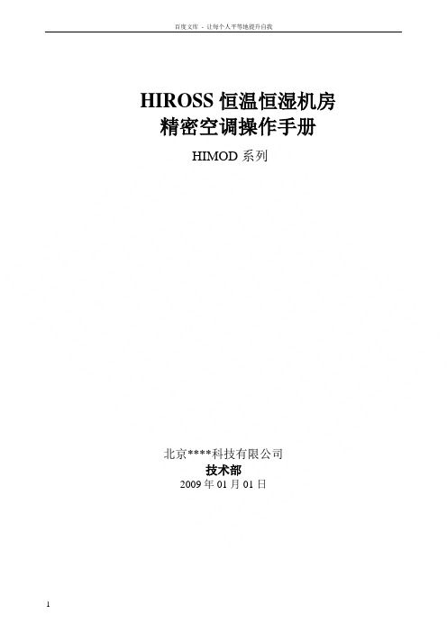
KC-3 KC-3 KC-3 MKC-2 KC-3
VALVE SERIES
W3 W6 W14
CURRENT VALVE TYPES
DISC
WITH
DIAPHRAGM
STAINLESS STEEL
INSERT
W3P1
–––
THE ABOVE PREFIXES MAY BE ADDED TO BASIC VALVE TYPE NUMBER (B25S2) TO REQUEST SPECIAL FEATURES.
Coil Size MKC-1 MKC-2 KC-3
2-398
2
Connection Type
Normally Open
Manual Lift Stem
Design Series
Port Size in 1/32"
Connections Solder
Coil Size
Connection Size
in 1/8"
0 - ODF X ODF 1 - ODF X ODM 2 - ODM X ODF
SPORLAN Solenoid Valves & Coil Replacement Guide Select Solenoid Valves According to Capacity — NOT Line Size
NORMALLY CLOSED VALVES
Form 30-122
March 1998
NORMALLY OPEN VALVES
OE9, OB9
Sporlan R-410A产品介绍说明书

Sporlan products suitable for R-410A are introduced in this publication,Including special features,specifications, and characteristics of the devices for R-410A systems. Additional features,specifications,and characteristics for other refrigerants are included in appropriate sections of the Sporlan Catalogue.For immediate access to Sporlan literature please visit .R-410A is a 50% / 50% blend,by weight,of R-32 and R-125. The vapor pressure of R-410A is almost 50% greater than R-22’s vapor pressure.New R-410A systems must be designed to handle the higher pressure and require special service tools,such as manifold gauge sets,recovery units,and recovery tanks.R-410A is intended for use solely with polyolester (POE) oil, while R-22 can be used with POE,Alkylbenzene,or Mineral Oil.The higher pressure,and the fact that R-410A performs very much like a single component refrigerant,provide an opportunity to produce a more compact system with greater efficiency.In addition,R-410A refrigerant allows more suction line pressure drop since it is less sensitive to suction line efficiency losses.The future of the HVAC & R market looks promising for the development and use of R-410A systems.Applications primarily include air conditioning,chillers and commercial refrigeration.The superior performance characteristics of R-410A and the industry’s transition to HFCs have made this refrigerant a viable alternative to R-22 and other refrigerants,and is becoming the refrigerant of choice for many new air conditioning and heat pump designs.Catalogue R-410A MEJuly 2001Page 2— Catalogue R-410A&E Z I B EZ I B B g u o r h T t h g i a r t &E Z I EZ I B B el g n A &E Z I B I B B C u o r h T t h g i a r EZ I B B C el g n A THERMOSTATIC EXPANSION VALVESSporlan offers thermostatic expansion valves in R-410A nominal capacities between 0.88 and 28 kW. The models offered are externally equalized, have straight through or angle configuration, and SAE or ODF connections. The Sporlan refrigerant code for R-410A is the letter "Z ",which is used in the designation of products especially designed for R-410A service.The BIZE models have a conventional port construction.BBIZE models have the advantage of a balanced port construction,which makes them ideally suited for systems with a wide range of operating conditions.The CBIZE and CBBIZE models are similar to the BIZE and BBIZE, but have an internal check valve to allow refrigerant flow to bypass the expansion valve port in the reverse flow direction in heat pump systems.The integral check valve means fewer connections, easier installation,and increased reliability.The Sporlan TEVs designed for R-410A have replaceable thermostatic elements with a locknut ring stronger than normally used with common refrigerants such as R-22 or R-134a. This feature makes the thermostatic element capable of withstanding higher pressures. Replaceable thermostatic elements are designated by “KT-45-” plus the charge.Example: KT-45-ZGA.Currently, three thermostatic charges are available for R-410A service:ZGA – Has similar performance to the VGA charge used in R-22or NGA charge used in R-407C systems. The constituents and heavy thermal ballasts in the charge provide excellent anti-hunt characteristics by dampening the valve in the opening direction. The maximum operating pressure or MOP of this charge is not as defined as the ZCP160 charge,an alternate charge for R-410A air conditioning and heat pump applications.ZCP160– Has similar performance to the VCP100 charge used in R-22 systems or the NCP100 charge used in R-407C systems. The maximum operating pressure or MOP of this charge takes effect around 12°C evaporator temperature.The ZCP160 charge has a mild thermal ballast that dampens the valve in the opening direction only.ZN – Has similar performance to the VN charge used in R-22or NN charge used in R-407C systems. A heavy thermal ballast dampens the valve in the opening and closing directions.The ZN charge is a non-condensable charge without an MOP, and thus not subject to charge migration. It is used in special medium and high temperature applications, such as chillers located outdoors that must operate while exposed to cold temperatures.Contact the nearest Acal sales office if you have an application that requires a valve or charge that is not listed.Catalogue R-410A — Page 3ODF ConnectionsPage 4— Catalogue R-410ABIZE & BBIZEStraight Through ConfigurationB55 mmADDCCBIZE & BBIZEAngle ConfigurationE n i m 9n i m 9n i m 7n i m 7ni m 1Capillary Tube Length 76.2 cm Standard 152.4 cm Available47 mm49 mm56 mm90 mm30°7.9 m m m i n .B I ZE = 46 m m B B I Z E = 47 m mBIZE 46 mm BBIZE 47 mmCC E E49 mm49 mmDDDDDBCE Equalizer Option:1/8" OD x 31 cm ,61 cm or 91 cmlong capillary tube external equalizer with or without 1/4" SAE flare nutEqualizer Option:1/8" OD x 31 cm,61 cm or 91 cm long capillary tube external equalizer with or without 1/4" SAE flare nutE EGGFA1/4" ODFExternal Equalizer Fitting 1/4" ODF external equalizer fitting35Catalogue R-410A — Page 5CBIZE & CBBIZEStraight Through ConfigurationCBBIZEAngle ConfigurationEqualizer option:1/8" OD x 31 cm,61 cm or 91 cm long capillary tube external equalizer with or without 1/4" SAE flare nutEqualizer option:1/8" OD x 31 cm,61 cm or 91 cmlong capillary tube external equalizer with or without 1/4" SAE flare nut58 mmABCC30°DDG46mm49 mm59 mm93 mmFCBDAEHChatleff fittingsoption7.9 m m m i n .48 m m O D F 41 m mS A E6.4 m m 49 mm49 mmPage 6— Catalogue R-410AFor more information on Sporlan distributors please refer to Bulletin 20-10.SOLENOID VALVESValves with 4 different port sizes and ODF solder connections are available. The smallest port valve uses a MKC-1 coil while the rest use a MKC-2 coil. Sporlan solenoid valves are available in many different voltage and cycle ratings. Standard coils are listed in the specifications table below.Solenoid coils are available with either an integral junction box, a 1/2" conduit boss, or DIN connector. Hirshman connectors are also available. Models with other sizes and features are under development. Please contact the nearest Acal sales office if you have an application that requires a solenoid valve with capacities or voltages not shown in this catalogue.Catalogue R-410A — Page 7E6 SeriesE19 SeriesCoil removal 40 mmCoil removal 45 mmCoil removal 45 mm*B*BAADDDD*BAACCC E E14 SeriesFor more information on solenoid valves refer to Bulletin 30-10E6S130-HPE19S250-HPME9S240-HPPage 8— Catalogue R-410ACatch-All ®FILTER-DRIERSAll sealed models of Sporlan’s Catch-All and the HPC-100(heat pump) models are suitable for use in R-410A systems. The high water capacity and the acid removal ability of the Catch-All core are well suited to meet the demands of R-410A refrigerant and POE oil.Extensive testing of the materials and the molded core in the Catch-All have demonstrated its compatibility and effectiveness in systems using R-410A. Form 40-139 has a detailed explanation of R-410A compatibility testing of the Catch-All.fittingsFiberglass pad 100 mesh screenH ea v yl ea f sp ri n gCatalogue R-410A — Page 9 It’s the CORE that Counts!Page 10— Catalogue R-410ASA-14SU For more information refer to Bulletin 70-10Overall width is:33 mm for 1/4" and 3/8" sizes, 40 mm for 1/2" and 5/8" sizes, and 35 mm for 7/8" and 1-1/8" sizes.Most solder connections can be used as male fittings as well as female fittings.The 1/4”ODF is 3/8" ODM, the 3/8" ODF is 1/2" ODM, the 1/2" ODF is 5/8" ODM, and the 5/8"ODF is 3/4"ODM.Models with female flare and/or swivel nut connections are supplied with a copper gasket in the fitting.* These models have copper connections and feature a removable element cartridge — for replacement cartridge specify AC-20.Note:Change or add Catch-All Filter-Drier when the paper turns from green to chartreuse .SA-13SCatalogue R-410A — Page 11Zhu Gao DeRm. 1010, Tower 1 Kerry Everbright City 218 Tian Mu Road West Shanghai 200070, P.R. of China Tel: (86) 21 6353 4577Fax: (86) 21 6354 1227E-mail:*******************Acal China China Acal plcAir Conditioning & RefrigerationHeadquarters Office United Kingdom Peter Hogan 2 Chancellor Court Occam Road, Surrey Research Park Guildford GU2 7AH, United Kingdom Tel: (44) 1483 544500 Fax: (44) 1483 544550E-mail:*****************.ukwebsite:Helen Rosalia 10 Cutter Mill Road, Suite 203Great Neck, New York 11021, U.S.A. Tel: (1) 516 487 9870 Fax: (1) 516 487 9342E-mail:***************website: Hugo Dalla ZannaRua Conde do Pinhal, 2267, Suite 201 CEP 13560-140São Carlos, SP , Brasil Tel: (55) 16 270 8027 Fax: (55) 16 270 1604E-mail:**************A cal New York Inc International Sales Headquarters (excludes Europe & Japan)Acal S.A.Acal Brazil Brazil U.S.A.New York France Eliane Emerit-Bonnot Zone d'Activite des Marais 1 Avenue Louison Bobet BP 6494122 Fontenay-sous-Bois,Cedex, France Tel: (33) 1 4514 7300 Fax: (33) 1 4877 6230E-mail:***********website: www.acal.fr Acal Controls Ltd.European Sales Office Headquarters (excludes France & Germany)England Angus Mackintosh Unit 2, The Rose Estate, Osborn Way Hook, Hampshire RG27 9UT, United Kingdom Tel: (44) 1256 382520Fax: (44) 1256 382530E-mail: **********************.uk website: Elke Villhauer Fischeracker 274223 Flein/Heilbronn, Germany Tel: (49) 7 131 5810 Fax: (49) 7 131 5812 90E-mail:************website: www.acal.de Acal GmbH Germany Tony Koh Tampines Central P.O. Box 400, Singapore 915214Tel: (65) 654 65461 Fax: (65) 654 65462E-mail:******************.sgAcal Singapore Singapore Sarkis Ohannessian P.O. Box 70-994Antelias, Lebanon Tel: (961) 4 522 309 Fax: (961) 4 522 309E-mail:****************.lb A cal Middle East Lebanon Anil Yadav 16/34 1st. Floor Sidhora Kalan Near Shakti Nagar Rly Bridge Delhi, India 110052Tel: (91) 11 364 3211 Fax: (91) 11 364 3212E-mail:******************Acal India India Mike Rivera PMB# 2195944 Coral Ridge Drive Coral Springs, Florida 33076, U.S.A.Tel: (1) 954 345 8278 Fax: (1) 954 255 6468E-mail:********************.net Acal Florida U.S.A.Florida Peter Harms Suite 3, 70 Kingsway Glen Waverley VIC 3150Tel: (61) 3 95747810Fax: (61) 3 9574 7820E-mail:****************Acal Australia Pty. Ltd.Australia。
Sporlan 蒸汽冷却控制器操作手册说明书
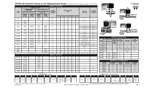
Sporlan Subcool Control Installa-tion and Operation Manual For detailed instructions, scan this QR code orgo to /SD-358M.htmsensors) should be supplied by Sporlan to ensure compatibility and proper operation. For optimal performance, a counterflow heat exchanger is recommended. There are no user-serviceable components inside the Sporlan Subcool Control. Opening the case will void the warranty.1. INSTALLATIONReference diagram on back of page. ForSubcool-O-Matic replacement see SD-358R. 1. Mount the controller in a rain-tight, pro-tected location using the supplied DIN rail. The suggested mounting area is 10 inches high and 5 inches wide, the mini-mum depth is 3 inches.2. Mount the liquid temperature sensorto the subcooled liquid outlet using the instructions provided with the sensor. Connect the non-polarized temperature sensor wires to terminals 29 and 30. Maximum torque on screw terminals is 3.5 in/lbs.Use caution when working around high voltage components.Safety covers should be used for personal safety on high voltage panels. Tools required:• Small flat screwdriver for terminals • Cordless screwdriver• Phillips and flat screwdrivers • Needle-nose pliers• Two #8 x ½” self-tapping screws tomount DIN rail2. SETUPEnter values for four system variables. The EEV is closed upon startup and the system will not operate until completing setup.Once powered up, the controller will display the firmware versions for the display and the controller. It will then display the first variable to set.1. Set StEP , Step Motor Stroke. Press andthen turn the SELECT button to select the correct number of steps for theEEV being used. Default is 2500. Press the SELECT button again to enter the value. The next variable is displayed.2. Set reFr , Refrigerant. Select theactual refrigerant used in the system, following the steps above. Default is 404A .Sporlan Subcool-O-Matic Replace-ment InstructionsFor Subcool-O-Matic replacement instructions, scan this QR code or go to /SD-358R.htm3. Mount the suction temperature sensorto the suction line after the evaporator following the instructions provided with the sensor. Connect the non-polarized sensor wires to terminals 31 and 32. 4. Mount the pressure transducer on thesuction line near the suction tempera-ture sensor, positioned at 12 o’clock. Connect the pressure transducer wires to terminals 33, 34, and 35. If the cable is spliced to extend its length, ensure that the new wire is properly connected.5. C onnect terminals 25 and 26 to a digitalinput. A short or a closed contact from an external relay will close the valve for pump down.6. Connect the Sporlan Electric ExpansionValve (EEV) wires to terminals 5, 6, 7, and 8.7. Connect power to terminals 1 and 2.Power requirements are 24 volts AC at 40 V A, Class II transformer.8. Remove the clear film from the front ofthe Subcool Control.3. OPERATIONFor further system tuning, adjust setpoints as described in document SD-358M. 1. Enter the Parameter Menu: Press andhold the SELECT knob for 5 seconds. Enter the password “111 ” and press the SELECT knob again.2. To change a parameter, rotate theSELECT knob to the desired param-eter and press the SELECT knob. The default parameter value will display. 3. Turn the SELECT knob to change theparameter value and then press the SELECT knob to enter the value and return to the Parameter Menu.4. After all parameters are set, turn theSELECT knob to “ESC ” and press the SELECT knob to save all changes. Observe the system for subcool operation.Note: The Parameter Menu times out after 60 seconds of inactivity andall changes entered will be lost.3. Set Pt4P , Pressure Sensor Type. SelectAbsolute or Gauge, following the steps above. Default is Gauge.4.Set Prng, Pressure Sensor Range.Select 150, 300, or 500 following the steps above. Default is 300.5. Once setup is complete, the displaywill alternate between LovT and actual Liquid Outlet Temperature. After the system is in operation, verify that the Liquid Outlet Temperature Setpoint, LoSP , is met. Default is 75 degrees.T emperature sensors should be mounted at either 4 or 8 o’clock, on a free-draining horizontal line.NOTE: If using a 3K temperature probe(or if unsure which probe you are using) refer to document SD-358M for instructions on how to set the controller to the correct probe profile.Parker Hannifin Corporation Sporlan Division206 Lange Drive • Washington, MO 63090 USA phone 636 239 1111 • fax 636 239 © 2011 Parker Hannifin Corporation092011 / SD-358QCounter Flow Brazed PlateHeat ExchangerDry Contacts (T4)Evap. Outlet Temp. (T1)Liquid Outlet Temp. (T2)White Green Black24V AC/DCRS485White B-GroundA+Suction Temperature SensorLiquid Temperature Sensor(optional)Temperature Sensor Warm Liquid In Pressure TransducerLiquid Inlet Temp. (T3)L1L2Liquid Line Solenoid ValveEEVSubcooled Liquid Out 10”-14”minimize 1”- 2” idealPumpdown Relay10”-14”Note: Use caution when working around high voltage components. Safety covers should be used for personal safety on high voltage panels.*Refer to the heat exchanger manufacturer’s installation/orientation instructions.Note: Piping and sensor insulation not shown.*。
- 1、下载文档前请自行甄别文档内容的完整性,平台不提供额外的编辑、内容补充、找答案等附加服务。
- 2、"仅部分预览"的文档,不可在线预览部分如存在完整性等问题,可反馈申请退款(可完整预览的文档不适用该条件!)。
- 3、如文档侵犯您的权益,请联系客服反馈,我们会尽快为您处理(人工客服工作时间:9:00-18:30)。
Sporlan产品
——制冷应用速选手册
前言
斯坡兰(Sporlan)拥有超过75年制冷系统部件供应、服务和系统解决方案的丰富经 验,并持续不断的改进、创新,以提供先进设计、完美制造、高品质产品服务于全球 制冷空调市场。
本手册重点介绍通用制冷系统的部件,如膨胀阀、电磁阀、干燥过滤器、压力控 制开关和压力调节阀等的选型和应用,其它系统部件或应用产品请联系Parker中国各 办事处。
• 最高感温包温度: 100ºC • 最高阀体温度: 121ºC • 最高环境温度: 60ºC • 短暂峰值温度: 149ºC • 最大工作压力: 34 bar • 最大测试压力: 38 bar
R22,R404A,R134a 等HFC,CFC 和HCFC制冷剂。
举例C8EF-VW:
C8
E
F
膨胀阀 类型:C8
R134a
0.44-9.5KW 内平衡或外平衡(0.14-2.71冷吨)
ERV ERVE OVE VVE WVE
Sporlan R22膨胀阀
1/3 1/2 1 2 (冷吨)
1.16-7KW
内平衡 1/3-2冷吨
1/3 1/2 1 2 3 4 5 6 8 10 12 (冷吨)
0.58-31.5KW
外平衡 1/6-9冷吨
9 12 21 30 35 38 45 (冷吨)
31.5-15.8KW
外平衡 9-45冷吨
50 70 (冷吨)
外平衡 50-70冷吨
133-245KW
ERJ
Sporlan R134a膨胀阀
C8膨胀阀 ER、EBS、O、V、W膨胀阀
Sporlan热力膨胀阀总览
热力膨胀阀
Sporlan C8可换阀芯热力膨胀阀名义制冷量
0.55(0.16) 1.1(0.3) 2.3(0.7) 3.5(1.0) 4.9(1.4) 8.4(2.4) 10.5(3.0) 14(4.0) kW(冷吨)
内平衡 外平衡1
内平衡 外平衡1
1. 平衡口(外平衡): 1/4 英寸SAE 喇叭口
进口 尺寸
3/8 英寸 SAE 喇叭口
出口 毛细管 蒸发温 尺寸 长度 度范围
1/2 英寸 SAE 喇叭口
1.5 米
-40ºC 至
+15 ºC
订货代码
30136-245 30136-242 30136-225 30136-204 30136-221 30136-200
1/6 1/4 1/2 1.5 (冷吨)
0.58-5.1KW
内平衡 1/6-1.5冷吨
1/4 1/2 1 1.5 2 3 4 5 9 (冷吨)
ERJE
0.88-32KW
外平衡 1/4-9冷吨 12 16 23 32 38 40 (冷吨)
ERS ERSE
OSE VSE
Sporlan R404A膨胀阀
1/6 1/4 1/2 1 1.5 (冷吨)
0.58-5.25KW
内平衡 1/6-1.5冷吨
1/6 1/4 1/2 1 1.5 2 3 3.5 4 5 6 7 9 (冷吨)
出口 毛细管 蒸发温 尺寸 长度 度范围
1/2 英寸 SAE 喇叭口
1.5 米
-40ºC 至
+15 ºC
订货代码
30136-247 30136-244 30136-239 30136-218 30136-235 30136-214
C8阀芯选型:
阀芯编号
R223
kW
TR
R404A3
kW
TR
R134a3
OJE
外平衡 12-40冷吨
42-140KW
C8热力膨胀阀
C8热力膨胀阀
产品简介
产品特点 技术规格 适用制冷剂 命名方式
通过感受蒸发器出口过热度的变化,C8热力膨胀阀用于调节液态制冷剂进入蒸发器 的供给量。C8膨胀阀广泛应用于商用制冷系统, 例如: • 超市用冷冻冷藏展示柜, • 冰淇淋机和冰淇淋柜, • 食品速冻设备, • 商用制冰机, • 冷冻冷藏车, • 中小型冷冻冷藏库, • 模块制冷机械(用于塑料、皮革冷却)
R22
0.55-14KW 内平衡或外平衡(0.16-4冷吨) 0.42(0.1) 0.77(0.2) 1.4(0.4) 2.1(0.6) 3.9(1.1) 6.3(1.8) 7.7(2.2) 8.2(2.3) kW(冷吨)
R404A
0.42-8.2KW 内平衡或外平衡(0.12-2.34冷吨) 0.44(0.1) 1.0(0.3) 1.6(0.5) 2.6(0.7) 4.3(1.2) 7(2.0) 8.6(2.5) 9.5(2.7) kW(冷吨)
1.16-42KW
外平衡 1/3-12冷吨
15 20 30 40 55 70 90 (冷吨)
52.5-315KW
外平衡 15-90冷吨
100 (冷吨)
外平衡 100冷吨
外平衡 135-180冷吨
135 180 (冷吨) 472.5-630KW
典型的制冷系统图:
曲轴箱 压力调节阀
热气电磁阀
热气旁通阀
压头调节阀
干燥过滤器
液路电磁阀
视液镜
热力或电子膨胀阀
吸气过滤器 蒸发压力调节阀
目录
热力膨胀阀............................................................................................................................. 2 喷液膨胀阀 .......................................................................................................................... 14 电子膨胀阀........................................................................................................................... 16 电子蒸发压力调节阀............................................................................................................ 21 电子驱动模块....................................................................................................................... 25 电磁阀.................................................................................................................................. 26 干燥过滤器........................................................................................................................... 37 滤芯...................................................................................................................................... 40 压力控制开关 ...................................................................................................................... 41 热气旁通阀........................................................................................................................... 42 避震管.................................................................................................................................. 45
2.2
8.6
2.5
C-06
14
4.0
8.2
2.3
9.5
2.7
3. 名义制冷量: (基于蒸发温度:+5 ºC, 冷凝温度:+32ºC, 阀前制冷剂温度+28ºC) 4. 阀芯组件表明刻有阀芯编号,例如:C-0X。 5. 每个阀芯都配备有一个独立的标签并安放在保护套管内,建议安装时与阀体一起固定
订货代码
C8阀体,喇叭口x焊接口选型:
制冷剂
阀类型
平衡口 类型
R22 R404A R134a
C8S-VW C8ES-VW C8S-SW C8ES-SW C8S-JW C8ES-JW
内平衡 外平衡2
内平衡 外平衡2
内平衡 外平衡2
2口 尺寸
3/8 英寸 SAE 喇叭口
C8热力膨胀阀
订货
阀芯组件4 阀芯标贴5
C8膨胀阀安装提示
C8膨胀阀订货时需选择并确定两种组件:阀体和阀芯。
C8阀体,喇叭口x喇叭口选型:
制冷剂 R22
R404A R134a