数控机床专业英语翻译题
数控专业英语
数控专业英语数控专业英语340个数控专业是一个与机器打交道的专业,当然也少不了英语的学习,以下是本店铺整理的数控专业英语,欢迎参考阅读!1、ROM n.只读存储器2、rotate v.旋转3、rotation n.旋转4、rotor n.转子5、rough adj.粗糙的6、RPM n.转/分7、RSTR(restart) v.重启动8、run v.运行9、sample n.样本,示例10、save v.存储11、save as 另存为12、scale n.尺度,标度13、scaling n.缩放比例14、schedule n.时间表,清单15、screen n.屏幕16、screw n.丝杠,螺杆17、search v.搜索18、second n.秒19、segment n.字段20、select v.选择21、selection n.选择22、self-diagnostic 自诊断23、sensor n.传感器24、sequence n.顺序25、sequence number 顺序号26、series n.系列,adj.串行的27、series spindle n.数字主轴28、servo n.伺服29、set v.设置30、setting n.设置31、shaft n.轴32、shape n.形状33、shift v.移位34、SIEMENSE(德国)西门子公司35、sign n.符号,标记36、signal n.信号37、skip v,n.跳步38、slave adj.从属的39、SLC n.小型逻辑控制器40、slide n.滑台,v.滑动41、slot n.槽42、slow adj.慢43、soft key n.软键盘44、software n.软件45、space n.空格,空间46、SPC n.增量式脉冲编码器47、speed n.速度48、spindle n.主轴49、SRAM n.静态随机存储器50、SRH(search) v.搜索51、start v.启动52、statement n.语句53、stator n.定子54、status n.状态55、step n.步56、stop v.停止,n.挡铁57、store v.储存58、strobe n.选通59、stroke n.行程60、subprogram n.子程序61、sum n.总和62、surface n.表面63、SV(servo) n.伺服64、switch n.开关65、switch off v.关断66、switch on v.接通67、symbol n.符号,标记68、synchronous adj.同步的69、SYS(system) n.系统70、system n.系统71、tab n.制表键72、table n.表格73、tail n.尾座74、tandem adv.一前一后,串联75、tandem control n.纵排控制(加载预负荷的控制方式)76、tank n.箱体77、tap n,v.攻丝78、tape n.磁带,纸带79、tape reader n.纸带阅读机80、tapping n.攻丝81、teach in 示教82、technique n.技术,工艺83、temperature n.温度84、test v,n.测试85、thread n.螺纹86、time n.时间,次数87、tolerance n.公差88、tool n.刀具,工具89、tool pot n.刀杯90、torque n.扭矩91、tower n.刀架,转塔92、trace n.轨迹,踪迹93、track n.轨迹,踪迹94、tranducer n.传感器95、transfer v.传输,传送96、transformer n.变压器97、traverse v.移动98、trigger v.触发99、turn v转动,n转,回合100、turn off v.关断101、turn on v.接通102、turning n.转动,车削103、unclamp v.松开104、unit n.单位,装置105、unload n.卸载106、unlock v.解锁107、UPS n.不间断电源108、user n.用户109、value n.值110、variable n.变量,adj.可变的111、velocity n.速度112、velocity loop n.速度环113、verify v.效验114、version n.版本115、vertical a.垂直的116、voltage n.电压117、warning n.警告118、waveform n.波形119、wear n,v.磨损120、weight n.重量,权重121、wheel n.轮子,砂轮122、window n.窗口,视窗123、workpiece n.工件124、write v.写入125、wrong n.错误,adj.错的126、year n.年127、zero n.零,零位128、zone n.区域129、increment n.增量130、incremental adj.增量的131、indeX 分度,索引132、initial adj.原始的133、initialization n.C523初始化134、initialize v.初始化135、input n.v.输入136、INS() v.插入137、v.插入138、instruction n.说明139、interface n.接口140、internal adj.内部的141、interpolate v.插补142、interpolation n.插补143、interrupt v.中断144、interruption n.中断145、intervent n.间隔,间歇146、involute n.渐开线147、ISO n.国际标准化组织148、jog n.点动149、jump v.跳转150、key n.键151、keyboard n.键盘152、label n.标记,标号153、ladder diagram 梯形图154、language n.语言155、lathe n.车床156、LCD n.液晶显示157、least adj.最小的158、length n.长度159、LIB(library) n.库160、library n.库161、life n.寿命162、light n.灯163、limit n.极限164、limit switch n.限位开关165、line n.直线166、linear adj.线性的167、linear scale n.直线式传感器168、link n,v.连接169、list n,v.列表170、load n.负荷,v.装载171、local adj.本地的172、locate v.定位,插销173、location n.定位,插销174、lock v.锁定175、logic n.逻辑176、look ahead v.预,超前177、loop n.回路,环路178、LS n.限位开关179、LSI n.大规模集成电路180、machine n.机床,v.加工181、macro n.宏182、macro program n.宏程序183、magazine n.刀库184、magnet n.磁体,磁185、magnetic a.磁的186、main program n.主程序187、maintain v.维护188、maintenance n.维护189、MAN(manual) n.手动190、management n.管理191、manual n.手动192、master adj.主要的193、maX adj.最大的,n.最大值194、maXimum adj.最大的,n.最大值195、MDI n.手动数据输入196、meaning n.意义197、measurement n.测量198、memory n.存储器199、menu n.菜单200、message n.信息201、meter n.米202、metric adj.米制的203、mill n.铣床,v.铣削204、min adj.最小的,n.最小值205、minimum adj.最小的,n.最小值206、minus v.减,adj.负的207、minute n.分钟208、mirror image n.镜像209、miscellaneous function n.辅助功能210、MMC n.人机通讯单元211、modal adj.模态的212、modal G code n.模态G代码213、mode n.方式214、model n.型号215、modify v.修改216、module n.模块217、MON(monitor) v.监控218、monitor v.监控219、month n.月份220、motion n.运动221、motor n.电机222、mouse n.鼠标223、MOV(移动) v.移动224、move v.移动225、movement n.移动226、multiply v.乘227、N number n.程序段号228、N.M n.牛顿。
数控英语测验2及答案

Test 2Major Name NumberI. Translate the WARNING into Chinese. (12分)WARNINGKeep hand body away from the tool operating area to prevent serious injury auto mode operation.SAFETY INSTRUCTION1. Be sure to switch to the manual mode at tool replacement.2. Be sure to turn off the power source at maintenance.3. Check if pull-stud is securely tightened to tool holder at tool loading.4. Load the tools in the magazine in a good balance.注意在自动运转模式下,要将身体远离刀具的操作范围,以免造成伤害。
安全操作指导1.确保在手动操作模式下更换刀具。
2.确保在关闭电源状态下,维修机器设备。
3.安装刀具时,确保刀具固定、拧紧。
4.刀具库中的刀具安装,要注意平衡。
II. Translate the following into Chinese (20分)1. Automation operation by NC is readily adaptable to the operation of all metalworking machines. Lathes, milling machines, drill machines, boring machines, grinding machines, turret punches, flame or wire-cutting machines and welding machines, and even pipe benders are available with numerical controls.数控加工制造目前已经广泛的应用于几乎所有的金属加工机床:车床,铣床,钻床,镗床,磨床,回转冲床,电火花或线切割机床和焊接机床,甚至弯管机也采用数控加工技术。
数控机床专业英语(超级棒).
3-Jaws indexing spacers 三爪、分割工具头A.T.C.system 加工中心机刀库Aluminum continuous melting & holding furnaces 连续溶解保温炉Balancing equipment 平衡设备Bayonet 卡口Bearing fittings 轴承配件Bearing processing equipment 轴承加工机Bearings 轴承Belt drive 带传动Bending machines 弯曲机Blades 刀片Blades,saw 锯片Bolts,screws & nuts 螺栓,螺帽与螺丝Boring heads 搪孔头Boring machines 镗床Cable making tools 造线机Casting,aluminium 铸铝Casting,copper 铸铜Casting,gray iron 铸灰口铁Casting,malleable iron 可锻铸铁Casting,other 其他铸造Casting,steel 铸钢Chain drive 链传动Chain making tools 造链机Chamfer machines 倒角机Chucks 夹盘Clamping/holding systems 夹具/支持系统CNC bending presses 电脑数控弯折机CNC boring machines 电脑数控镗床CNC drilling machines 电脑数控钻床CNC EDM wire-cutting machines 电脑数控电火花线切削机CNC electric discharge machines 电脑数控电火花机CNC engraving machines 电脑数控雕刻机CNC grinding machines 电脑数控磨床CNC lathes 电脑数控车床CNC machine tool fittings 电脑数控机床配件CNC milling machines 电脑数控铣床CNC shearing machines 电脑数控剪切机CNC toolings CNC刀杆CNC wire-cutting machines 电脑数控线切削机Conveying chains 输送链Coolers 冷却机Coupling 联轴器Crimping tools 卷边工具Cutters 刀具Cutting-off machines 切断机Diamond cutters 钻石刀具Dicing saws 晶圆切割机Die casting dies 压铸冲模Die casting machines 压铸机Dies-progressive 连续冲模Disposable toolholder bits 舍弃式刀头Drawing machines 拔丝机Drilling machines 钻床Drilling machines bench 钻床工作台Drilling machines,high-speed 高速钻床Drilling machines,multi-spindle 多轴钻床Drilling machines,radial 摇臂钻床Drilling machines,vertical 立式钻床drills 钻头Electric discharge machines(EDM) 电火花机Electric power tools 电动刀具Engraving machines 雕刻机Engraving machines,laser 激光雕刻机Etching machines 蚀刻机Finishing machines 修整机Fixture 夹具Forging dies 锻模Forging,aluminium 锻铝Forging,cold 冷锻Forging,copper 铜锻Forging,other 其他锻造Forging,steel 钢锻Foundry equipment 铸造设备Gear cutting machines 齿轮切削机Gears 齿轮Gravity casting machines 重力铸造机Grinder bench 磨床工作台Grinders,thread 螺纹磨床Grinders,tools & cutters 工具磨床Grinders,ultrasonic 超声波打磨机Grinding machines 磨床Grinding machines,centerless 无心磨床Grinding machines,cylindrical 外圆磨床Grinding machines,universal 万能磨床Grinding tools 磨削工具Grinding wheels 磨轮Hand tools 手工具Hard/soft and free expansion sheet making plant 硬(软)板(片)材与自由发泡板机组Heat preserving furnaces 保温炉Heating treatment funaces 熔热处理炉Honing machines 搪磨机Hydraulic components 液压元件Hydraulic power tools 液压工具Hydraulic power units 液压动力元件Hydraulic rotary cylinders 液压回转缸Jigs 钻模Lapping machines 精研机Lapping machines,centerless 无心精研机Laser cutting 激光切割Laser cutting for SMT stensil 激光钢板切割机Lathe bench 车床工作台Lathes,automatic 自动车床Lathes,heavy-duty 重型车床Lathes,high-speed 高速车床Lathes,turret 六角车床Lathes,vertical 立式车床Lubricants 润滑液Lubrication Systems 润滑系统Lubricators 注油机Machining centers,general 通用加工中心Machining centers,horizontal 卧式加工中心Machining centers,horizontal & vertical 卧式与立式加工中心Machining centers,vertical 立式加工中心Machining centers,vertical double-column type 立式双柱加工中心Magnetic tools 磁性工具Manifolds 集合管Milling heads 铣头Milling machines 铣床Milling machines,bed type 床身式铣床Milling machines,duplicating 仿形铣床Milling machines,horizontal 卧式铣床Milling machines,turret vertical 六角立式铣床Milling machines,universal 万能铣床Milling machines,vertical 立式铣床Milling machines,vertical & horizontal 立式与卧式铣床Mold & die components 模具单元Mold changing systems 换模系统Mold core 模芯Mold heaters/chillers 模具加热器/冷却器Mold polishing/texturing 模具打磨/磨纹Mold repair 模具维修Molds 模具Nail making machines 造钉机Oil coolers 油冷却器Overflow cutting machines for aluminium wheels 铝轮冒口切断机P type PVC waterproof rolled sheet making plant P型PVC高分子防水PCB fine piecing systems 印刷电器板油压冲孔脱料系统Pipe & tube making machines 管筒制造机Planing machines 刨床Planing machines vertical 立式刨床Pneumatic hydraulic clamps 气油压虎钳Pneumatic power tools 气动工具Powder metallurgic forming machines 粉末冶金成型机Presses,cold forging 冷锻冲压机presses,crank 曲柄压力机Presses,eccentric 离心压力机Presses,forging 锻压机Presses,hydraulic 液压冲床Presses,knuckle joint 肘杆式压力机Presses,pneumatic 气动冲床Presses,servo 伺服冲床Presses,transfer 自动压力机Pressing dies 压模Punch formers 冲子研磨器Quick die change systems 速换模系统Quick mold change systems 快速换模系统Reverberatory furnaces 反射炉Rollers 滚筒Rolling machines 辗压机Rotary tables 转台Sawing machines 锯床Sawing machines,band 带锯床Saws,band 带锯Saws,hack 弓锯Saws,horizontal band 卧式带锯Saws,vertical band 立式带锯shafts 轴Shapers 牛头刨床Shearing machines 剪切机Sheet metal forming machines 金属板成型机Sheet metal working machines 金属板加工机Slotting machines 插床spindles 主轴Stamping parts 冲压机Straightening machines 矫直机Switches & buttons 开关与按钮Tapping machines 攻螺丝机Transmitted chains 传动链Tube bending machines 弯管机Vertical hydraulic broaching machine 立式油压拉床Vises 虎钳Vises,tool-maker 精密平口钳Wheel dressers 砂轮修整器Woven-Cutting machines 织麦激光切割机Wrenches 扳手Assembly line组装线Layout布置图Conveyer流水线物料板Rivet table拉钉机Rivet gun拉钉枪Screw driver起子Electric screw driver电动起子Pneumatic screw driver气动起子worktable 工作桌OOBA开箱检查fit together组装在一起fasten锁紧(螺丝)fixture 夹具(治具)pallet栈板barcode条码barcode scanner条码扫描器fuse together熔合fuse machine热熔机repair修理operator作业员QC品管supervisor 课长ME制造工程师MT制造生技cosmetic inspect外观检查inner parts inspect内部检查thumb screw大头螺丝lbs. inch镑、英寸EMI gasket导电条front plate前板rear plate后板chassis 基座bezel panel面板power button电源按键reset button重置键Hi-pot test of SPS高源高压测试Voltage switch of SPS电源电压接拉键sheet metal parts 冲件plastic parts塑胶件SOP制造作业程序material check list物料检查表work cell工作间trolley台车carton纸箱sub-line支线left fork叉车personnel resource department 人力资源部production department生产部门planning department企划部QC Section品管科stamping factory冲压厂painting factory烤漆厂molding factory成型厂common equipment常用设备uncoiler and straightener整平机punching machine 冲床robot机械手hydraulic machine油压机lathe车床planer、plein刨床miller铣床grinder磨床driller床linear cutting线切割electrical sparkle电火花welder电焊机staker=reviting machine铆合机position职务president董事长general manager总经理special assistant manager特助factory director厂长department director部长deputy manager、vice manager副理section supervisor课长deputy section supervisor、vice section superisor副课长group leader/supervisor组长line supervisor线长assistant manager助理to move, to carry, to handle搬运be put in storage入库pack packing包装to apply oil擦油to file burr 锉毛刺final inspection终检to connect material接料to reverse material 翻料wet station沾湿台Tiana天那水cleaning cloth抹布 to load material上料to unload material卸料to return material/stock to退料scraped 报废scrape 刮;削deficient purchase 来料不良 manufacture procedure 制程rotating speed, revolution 转速deficient manufacturing procedure 制程不良delivery deadline交货期oxidation 氧化scratch 刮伤dents 压痕defective upsiding down抽芽不良defective to staking 铆合不良embedded lump 镶块feeding is not in place 送料不到位stamping-missing 漏冲production capacity 生产力education and training 教育与训练proposal improvement 提案改善spare parts、buffer 备件forklift叉车trailer、long vehicle拖板车compound die合模die locker锁模器pressure plate、plate pinch压板bolt螺栓name of a department部门名称administration/general affairs dept总务部automatic screwdriver电动启子thickness gauge厚薄规gauge(or jig)治具power wire电源线buzzle蜂鸣器defective product label不良标签identifying sheet list标示单screwdriver holder起子插座pedal踩踏板stopper阻挡器flow board流水板hydraulic handjack油压板车forklift叉车pallet栈板glove(s)手套glove(s) with exposed fingers割手套thumb大拇指forefinger食指midfinger中指ring finger无名指little finger小指band-aid创可贴garbage can垃圾箱garbage bag垃圾袋chain链条jack升降机production line流水线chain链条槽magnetizer加磁器lamp holder灯架to mop the floor拖地to clean the floor扫地to clean a table擦桌子air pipe 气管packaging tool打包机packaging打包missing part漏件wrong part错件excessive defects过多的缺陷critical defect极严重缺陷major defect主要缺陷minor defect次要缺陷not up to standard不合规格dimension/size is a little bigger尺寸偏大(小) cosmetic defect外观不良slipped screwhead/slippery screw head螺丝滑头slipped screwhead/shippery screw thread滑手speckle斑点mildewed、moldy、mouldy发霉rust生锈deformation变形burr(金属)flash(塑件)毛边poor staking铆合不良excesssive gap间隙过大grease/oil stains油污inclusion杂质painting peel off脏污 shrinking/shrinkage缩水 mixed color杂色scratch划伤 poor processing 制程不良poor incoming part事件不良fold of pakaging belt打包带折皱painting make-up补漆discoloration羿色water spots水渍polishing/surface processing表面处理exposed metal/bare metal金属裸露 garbage container灰箕cost成本engineering工程die repair模修enterprise plan、enterprise expansionprojects企划QC品管die worker模工production, to produce生产equipment设备 to start a press开机stop/switch off a press关机classification整理regulation整顿cleanness清扫conservation清洁culture教养qualified products, up-to-grade products良品defective products, not up-to-grade products不良品waste废料board看板feeder送料机sliding rack滑料架defective product box不良品箱die change 换模to fix a die装模to take apart a die拆模to repair a die修模packing material包材basket蝴蝶竺plastic basket胶筐isolating plate baffle plate; barricade隔板 carton box纸箱to pull and stretch拉深to put material in place, to cut material, to input落料to impose lines压线to compress, compressing压缩character die字模to feed, feeding送料transportation运输(be)qualfied, up to grade合格not up to grade, not qualified不合格material change, stock change材料变更feature change 特性变更manufacture management制造管理abnormal handling异常处理production unit生产单位lack of painting烤漆不到位safety安全quality品质evaluation评估prepare for, make preparations for 准备parameters参数vaccum cleaner吸尘器rag 抹布lots of production生产批量steel plate钢板roll material卷料manufacture procedure制程operation procedure作业流程to revise, modify修订to switch over to, switch、to throw、over switching over切换engineering, project difficulty 工程瓶颈stage die工程模automation自动化to stake, staking, reviting铆合add lubricating oil加润滑油shut die架模shut height of a die架模高度analog-mode device类模器die lifter举模器argon welding氩焊vocabulary for stampingiudustrial alcohol工业酒精alcohol container沾湿台head of screwdriver起子头sweeper扫把mop拖把pneumatic 气动的,空气的,pneumatic control 气动控制electromechanical 机电的governor 操纵杆,控制器electronic governor 电子调速器screw machine 车丝机relay 继电器timer定时器counter 计数器inherent固有的,本质的,inherent problem本质问题versatile通用,多用途的filter out过滤ladder diagram梯形图symbology符号体系contact dot接点,触点instantaneously瞬时地magnet-opened contact switch 电磁触点开关architecture构造,结构,组织implementation工具,仪器,实现thumbwheel switch指轮(微调)开关breadboard实验电路板Hardwired relay panel分立(硬连线)延时,控制面板relay module继电模块capability性能,耐受力category分类single throw单掷开关double throw switch双掷开关double-pole双极(刀开关)double-pole single throw双刀单掷开关selector switch选择开关push-button switch按钮开关proximity switch接近开关level switch (信号)液位开关thumbwheel拨轮debug调试be population for……application在……应用很广泛electromechanical control机电控制exce pt that ……除……之外be available可利用的wiring out布线图milling cutter铣刀profile轮廓,外形,断面machine tool机床perforated tape穿孔带mature成熟hard-wire硬线连接punched tape冲孔带magnetic tape磁带lathe车床turning machine车削中心punch冲床significant显著encoder编码器resolve分解,决定utilize利用magnetic磁的photoelectric光电的binary code二进制码execution cycle执行循环electronic pulse脉冲spindle主轴,转轴lead screw丝杠,螺杆turret转台,转塔刀架servomotor伺服电机machining center加工中心electric discharge machine (EDM) 电火花机床grinder磨床testing and inspection equipment测试和检测设备conventional machining常规加工recommendation for…… 关于……推荐值scrap rate废品率incorporate插(引,加,编)入quality assurance质量保证spot check点检,抽查set up安装set up method安装方法set up time按照时间assembly装配,组装件notation符号,符号表示法binary二进制accomplish完成,实现sensing传感graduate刻度backlash后座力adjacent毗连的radius半径,范围intersection交叉,交集slide刀架,滑板,滑移fluid servomotor液压伺服器open-loop开环close-loop闭环direct current (DC) 直流电alternative current (AC)交流电gear mechanism齿轮机构pneumatic motor气动马达(气泵)processed with继续(更新)discrepancy偏(误)差,不同speed discrepancy转速差transducer传感器,转换器magazine链式刀库,杂志magazine feed自动传输带(送料带)magazine tool刀库magazine attachment机床送料装置retrieve检索,查询retrieval data检索数据retrieval program检索程序。
数控机床专业英语翻译题
数控机床专业英语翻译题Journal of Cleaner ProductionVolume 137, 20 November 2016, Pages 361–369Analytical approach to establishment of predictivemodels of power consumption of machine tools' auxiliary unitsMachine tool;Energy model;Energy consumption;EcodesignThe issue of production machine energy consumption has been recently gaining prominence, particularly due to the efforts made by the developed countries to reduce the impact of human activity on the environment. Since the operation of production machines is very energy-demanding, it is during their operation that production machines contribute to damaging the environment the most, as shown by previous studies (CECIMO, 2009). Rising energy prices together with efforts to reduce manufacturing costs have resulted in machine tool users request for minimizing energy demands of manufacturing. This pressure on production machine producers is further increased by the EU directive on reducing energy demands in all areas of human activity, in particular in industrial production, where production machines are significant energy consumers (European Union, 2009). In order to meet the objective of reducing production machine energy demands, it is necessary to consider potential energy savings already during the design stage of thesemachines or when planning production on these machines. Simulation of energy consumption during the design phase of the machine or technology can be an advantage giving an overview on costs of planned production which is nowadays one of the current issues. This cannot be achieved without the application of predictive models of energy consumption. A large part of studies and models that have been carried out so far focuses in particular on predicting the consumption of drives. However, the contribution of auxiliary units to total energy consumption is significant and often higher (Holkup et al., 2013). Therefore, it is necessary to deal with them in further development of energy consumption predictive models systematically and to give them the attention they deserve.1.1. State of the artDraganescu et al (Draganescu et al., 2003). studied the influence of cutting conditions on machine tool efficiency and power consumption. They searched for a mutual relationship between these two parameters based on practical tests. Weinert et al (Weinert et al., 2004). focused on the possibilities of reducing the amount of cutting fluid used during machining, which is one of the methods of reducing manufacturing costs. Although they did not examine the effect on energy consumption directly, they are often mentioned since their research made it possible to increase cutting speeds. This allowed reduction in manufacturing time, an essential parameter affecting machine tool consumption. Rangarajan and Dornfeld (Rangarajan and Dornfeld, 2004) were also aware of the significant role operating times play in reducing energy consumption. They focused on the optimization of cutting tool paths duringmachining. They also investigated the influence of workpiece clamping orientation on total time of machining planar surfaces. Gutowski et al (Gutowski et al., 2006). were the first to apply an exergic approach to energy consumption of manufacturing processes (exergy measures the potential of materials to do work). Based on this approach, Gutowski created a simple model of machine tool power consumption (1). This model is based on the simplistic assumption that the consumption of auxiliary units is independent of the machining process. Using tests, he also discovered that the consumption of these units may approximately constitute up to 85% of total machine tool energy consumption.equation(1)Turn MathJaxonwhere E [Ws] is the total energy consumed by the machine tool, P0 [W] is the idle power, k[Wsm?3] is the specific cutting process energy, [m3s] is the material removal rate and t[s] is total machining time.This research was followed by Diaz et al. (Diaz et al., 2011), who focused on identification of relationships between cutting conditions represented by material removal rate, active power requirement and total energy consumption. Kara and Li (Kara and Li, 2011) brought new insights into energy consumption of production machines. They considered the machine as a holistic system, which is able to influence its subsections. Therefore, it is necessary to deal with the relationships between these subsections as it is no longer possible to strictly divide energy consumption between the cutting process and auxiliary units as has been the practice so far. Mori et al (Mori et al., 2011). focused on the possibilities of energy savings using enhancedacceleration and deceleration control with added synchronisation of the spindle with feed axes. Their improved model included power demand for the spindle to accelerate or decelerate. Mativenga and Rajemi (Mativenga and Rajemi, 2011) focused on the selection of optimum cutting conditions with respect to cutting tool lifetime. This initiated a discussion on power consumption during tool exchange. Li and Yan (Li et al., 2013) dealt with modelling machine tool energy consumption and established a refined empirical model of machine tool active power, which achieves significantly more accurate results in comparison with predictive models of their predecessors. In their further research, they looked at multicriterial optimization of cutting conditions as a search for a compromise between material removal rate, power consumption and surface quality (Yan and Li, 2013). Avram and Xirouchakis (Avram and Xirouchakis, 2011) focusedon predictive models of energy consumption using NC code analysis. A similar sophisticated model (2) was also developed by He et al. (He et al., 2012). equation(2)Et o t a l =Es p i n d l e+Ef e e d+Et o o l+Ec o o l+Ef i xTurn MathJaxonwhere E total [Ws] is the total direct requirements, E spindle [Ws] is spindle energy requirements for the main cutting motion, E feed [Ws] is feed axes requirements for secondary cutting motions, E tool [Ws] is tool exchange energy requirements, E cool [Ws] is energy of cutting process cooling and E fix [Ws] is machine energy requirements.The research of the above-mentioned authors was further continued by Balogun and Mativenga (Balogun and Mativenga, 2013) and Dietmair and Verl (Dietmair and Verl, 2009), who developed own advanced models of energy consumption. These models use a division of the entire working cycle according to machine regimes. Witt et al (Witt et al., 2014). developed simulation software for real-time energy consumption and manufacturing cost predictions. This software is capable of providing valuable information already in the production planning phase. It uses data from a real control system (hardware in the loop) for the prediction of energy consumption of drives. As many other authors, they are confronted with the issue of determining the consumption of a substantial part of auxiliary units, which significantly contribute to the total consumption of a machine tool.The analysis of existing machine tool energy models leads to conclusion that consumption of auxiliary units can be higher than consumption of drives. Unfortunately not so many researchers have been interested in the precise modelling of energy consumption of machine tools auxiliary units yet. Therefore this part of the simulation should be investigated in more details.1.2. Research aim and scopeThis paper proposes an analytical approach to theestablishment of predictive models of power consumption of machine tools' auxiliary units. An estimation of power consumption of auxiliary units acquired by the model described below together with the consumption of drives. Drives can be predicted using the already published models and it will provide machine tool users with insights into total energy demands during production. The main objective of using this analytical approach is an increasing of the conformity between the consumption predicted by the model and the actual consumption of a machine tool.2. Method of modellingIn this chapter a creation process of energy models of machine tools especially of their auxiliary units will be described.2.1. Model establishmentThe evaluation of the proposed model (see Fig. 1) can be described in the following three steps:Step 1. Analysis of all installed machine auxiliary units and theirbehaviour.Step 2. Establishment of submodels of analyzed auxiliary units.Step 3. Sum of energy flows of all auxiliary units, including theconsumption of compressed air and drives.Fig. 1.Model of machine tool energy consumption.Figure options2.2. Core of modelThe core of the established model may be mathematically described by three basic equations. They express the relationshipbetween the active power of the device and its activity (3), the above-mentioned summation of energy flows (4) and subsequent calculation of the energy consumed (5).equation(3)Pi (t)=A(t)·Pi n p u tTurn MathJaxonwhere P i?(t) [W] is the time characteristic of the active power of a given auxiliary unit, A(t) [?] is the time characteristic of activity of a given auxiliary unit and P input [W] is the required active power of a given auxiliary unit in normal operation.equation(4)Turn MathJaxonwhere P total?(t) [W] is the time characteristic of total active power of the machine, P drive?(t) [W] is the time characteristic of active power of machinedrives, P air?(t) [W] is the time characteristic of equivalent active power of auxiliary units powered by compressed air (see Eq. (6)) and P i?(t) [W] is the time characteristic of active power of individual auxiliary units included in the model.equation(5)Turn MathJaxonwhere E total [Ws] is total consumed energy of the machine, P total?(t) [W] is the time characteristic of total active power of the machine, T [s] is totalsimulation time, is the vector of machine active powers and is thevector of simulation time increments.The complexity of the model is dependent on the number ofauxiliary units included in the model. It is also dependent on their selected main properties and their energy behaviour.2.3. Auxiliary units categorizationThe auxiliary units is possible classify according to the following basic criteria. Criterion 1 – mode of operation The mode of operation is mainly influenced by time parameters that are entered into appropriate submodels. Based on this criterion, the following types of auxiliary units are distinguished (see Fig. 2).Fig. 2.Classification of auxiliary units based on mode of operation.Criterion 2 – autonomy of auxiliary units behaviourThe autonomy of auxiliary units control is an important factor, which is an expression of the relationship between the control system of the machine and the controlled auxiliary unit. This key property of auxiliary units influences the possibility of predicting their activity based on knowledge of machine control system commands. Based on the autonomy of control, auxiliary units can be divided into three groups (see Fig. 3).Fig. 3.Classification of auxiliary units based on the autonomy of their control.Figure options Non-autonomous auxiliary units are controlled directly by the machine control system and have no other regulation that would influence their operation and active power. Semi-autonomous auxiliary units are operated by the machine control system and they have their own autonomous regulation, which influences their activity. Fully-autonomous auxiliary units are not controlled by the machine control system and are completely independent on it.Criterion 3 – type of performance controlThe type of performance control of auxiliary units is the next criterion directly influences the complexity of submodels and thus in particular input performance parameters. The following types of auxiliary units control are significant (see Fig. 4). Auxiliary units with one-level control only operate in ON/OFF regime, whereas auxiliary units with discrete multi-level control operate on several discrete performance levels. Auxiliary units with continuous control can work in all performance level of the entire range.Fig. 4.Classification of auxiliary units based on the type of performance control.Figure optionsCriterion 4 – type of operation initializationThe mode of operation initialization of auxiliary units significantly influences the ability to predict their activity in advance. Based on this criterion, the following basic types of auxiliary units initialization can be distinguished:AUTO The characteristic of activity of auxiliary units with automatic operation initialization is determined by the machine producer and their behaviour cannot be influenced by the machine user (for example electric cabinet air conditioning). The activity of auxiliary units can be predicted only based on a thorough knowledge of the PLC programme.SEMI Auxiliary units with semi-automatic operation initialization are initialized by the NC programme (for example tool edge cooling). Their activity can be predicted based on the NC programme analysis.MAN Auxiliary units with manual operation initialization areinitialized manually by a machine operator using the control panel. The characteristic of their activity is very difficult to predict or they are completely unpredictable.2.4. Acquiring submodel input parametersClassification of auxiliary units based on the above-mentioned criteria has a significant impact on the complexity of submodels and their performance parameters. These parameters may be determined in two ways, i.e. directly without measuring on the machine and indirectly by measuring on the machine.Time parameters and some performance parameters that may be determined directly without measuring on the machine. Time parameters may be acquired for example by a time analysis of the NC programme. Some performance parameters may be obtained in the same manner although the model established in this manner may provide very rough results (the upper limit of consumption). It is primarily performance parameters of individual auxiliary units that are determined indirectly by measuring on the machine. Using parameters obtained by measuring on a specific machine tool, relatively accurate results of energy consumption calculation are obtained.2.5. Submodels of selected auxiliary unitsA typical representative of auxiliary units that are difficult to simulate are air conditioning of an electrical cabinet of a machine tool. These auxiliary units usually belong to automatically operated devices with own autonomous regulation. Performed measurements (see Fig. 5) showed that at the beginning of the machine operation the period between the activation of the air conditioning became gradually shorter due to rising temperature of elements in the electrical cabinet. Later, the number of activations became stable, which is caused by stabilization oftemperature in the electrical cabinet. It can be assumed that unless there is a dramatic change in machine tool load or ambient conditions, the air-conditioning unit will continue to be activated in this periodic manner.Fig. 5.Time characteristic of active power of electrical cabinet cooling unit.Figure options These auxiliary units are usually replaced by an average value in models, so called “simple-submodel”. In case of long-term simulation the difference between model and reality can be neglected. For middle-term simulation it is more appropriate to select an enhanced submodel (combined-submodel of a permanently working and periodically started device). This enhancedsubmodel provides a higher degree of compliance with more negligible error in comparison with a simple-submodel.The combined-submodels may be also used for example in modelling machine tool fluid systems. This is evident from the active power measuring of auxiliary units on the three axis milling machine (see Fig. 6). The fluid systems for coolant comprise of a complex set of pumps. The main pump works continuously from its initialization by an appropriate M function in the NC programme, whereas the transfer pump is initialized discontinuously depending on the drop of fluid level in the tank.Fig. 6.Time characteristic of active power of selected machine tool auxiliary units.Figure options Another type of submodel is a division of the total operation of a selected auxiliary unit into two and more sections (run-up and operation). This type of submodel is forinstance applicable to the unit responsible for sucking vapour from the workspace as shown by the same measurement performed on the three axis milling machine (see Fig. 6). Measurements revealed that active power during the run-up of this unit is approximately double the normal operation active power and the run-up itself takes approximately from 3 to 5 s. Apart from electric appliances, it is also necessary to consider the electric equivalent of air consumption according the equation (6) (Holkup et al., 2013). equation(6)Pa i r (t)=c·Qa i r(t)Turn MathJaxonwhere P air?(t) [W] is the time characteristic of equivalent active power of auxiliary units powered by compressed air, c [Wdm?3min] is the conversion ratio between compressor active power and flow of air into the machine for a given compressed air distribution system and Q air(t) [dm3min?1] is the time characteristic of flow of compressed air into given auxiliary units in the machine.Using this calculation of compressed air equivalent active power (6) is possible to improve any standard models they do not account with this like (1) and (2).As shown by the measurement results (see Fig. 7), compressed air consumption in this specific case is a typical area where it is possible to replace the measured characteristic by the average value for the calculation of consumption. This is due to the fact that in 80% of the monitored characteristic the value of average and real compressed air flow differs approximately onlyby 10%. However, it depends on the specific type of machine and the number of installed auxiliary units powered by air as well as on the quality of elements used and compressed air distribution with respect to leakage. Last but not least, the machine working regime is important as well.Fig. 7.Time characteristic of compressed air flow into the machine.Figure options3. Experiment proposalAn experiment was proposed in order to compare the accuracy of the model of machine tool auxiliary units energy consumption and measurements on a real machine. The experiment was performed on the three axis horizontal milling machine (see Fig. 8 and Table 1).Table optionsexternal cooling of cutting tool (M8).flushing chips from workspace (M20, M22).lubricating unit.Fig. 10.Time characteristic of total active power of machine tool auxiliary units (uncalibratedmodel).Figure optionsFig. 11.Time characteristic of total energy consumed by machine tool auxiliary units(uncalibrated model).Figure options Therefore, it is necessary to perform a simple calibration of real energy consumption of all auxiliary units used for the model. Each unit is measured separately and real consumption is monitored. This simple calibration resulted in greater accuracy of input performance parameters of monitored auxiliary units submodels. These calibrated data are than used to make a verification measurement with the proposed model.4.2. Model verificationThis calibration led to greater accuracy of the calculation of the total energy consumed as shown in Fig. 12 and Fig. 13. The error of the model is now around 12?% during the whole simulation period. This difference is caused by unknown energy consumer activity during the last phase of the measuring. In case of simulation of all known consumers in ti me 0 to 700?s, the accuracy of the model is around 1?%. This difference is discussed in the next chapter.Fig. 12.Time characteristic of total active power of machine tool auxiliary units (calibratedmodel).Figure optionsFig. 13.Time characteristic of total energy consumed by machine tool auxiliary units(calibrated model).Figure options4.3. DiscussionClear error that is noticeable from the comparison of real and predicted machine tool active power is the activity of an unidentified auxiliary unit in the time section from 700 to 720?s.An error of the model relative to the measurements arose during the activity of this auxiliary unit. The relative deviation of the modelled consumption in comparison to the measured consumption was 1?% until this moment in time. However, it rose to final 12?% due to the activity of the unidentified auxiliary unit. This situation shows the necessity to know all energy consumers and account with them in the modeleven if it looks like negligible from the point of view actual power input. The overall energy consumption calculation can be significantly affected.Another small error is evident from the time characteristic of total active power of the monitored group of auxiliary units. The model contains errors in the time offset of initialization of given auxiliary units. In this case, these errors are caused by the method of NC code analysis, which failed to take into account transfer delays in initializing individual auxiliary units. These errors may be suppressed by using real or simulated control systems (e.g. virtual iTNC). However, the impact on total consumed energy in the performed test is minimal (see Fig. 13).5. ConclusionsThe functionality of the simple model was proved. The performed tests showed the great significance of a thorough identification of all auxiliary units contributing to energy consumption. This accurate identification of machine tool auxiliary units is an important factor affecting the resultant accuracy of the model of the entire machine tool. The necessary step is to calibrate the real consumption of tested units and devices because the plates parameters and real situation can be quite different. Without this calibration, the accuracy of the modelling is not good.The next issue for the modelling is to have a proper time line for the activation of tested devices. Therefore, the next step would be using the virtual control system with the real PLC setting to cover drives performance such as real positioning and speed control loops. Due to this model improvement, a better time line of the machining and auxiliary unit initialization can be achieved to make a more accurate simulation of energy consumption.AcknowledgementThe paper has received funding from the Technology Agency of the Czech Republic。
数控英语试题2

一.英汉互译(20分)theputer-assisted programming2.machining cycle3.Word Address Format4.miscellaneous function address5.broach6.swarf7.bar feed8.variation9.register10.传动装置11.传动12.刀具13.车刀14.梳刀15.程序段16.铣刀17.钻孔18.字符19.手工编程二.将下列英语翻译成汉语。
(30分)1.Good morning, everyone. Today we will take an overall tour of the workshop, and you will get to know how different parts are arranged and how they work together.各位早上好。
今天我们将对车间进行整体参观,你们会了解到不同部分如何安排以及如何一起工作。
2.The entire information about an operation is called a block. Thereare 3 types of formats for representing the block——Fixed sequential Format, Word address format, and Tab Sequential Format.一个操作的完整信息叫做程序段。
程序段有三种格式:固定顺序格式,字地址格式,分隔符顺序格式。
3.Sequence is not necessary in this format because all information is labeled by a letter. Repetition is not necessary either since the controller can take it from the earlier block.在这个格式中顺序是不必要的,因为所有信息都用字母标记了。
《数控技术(双语)》习题参考答案
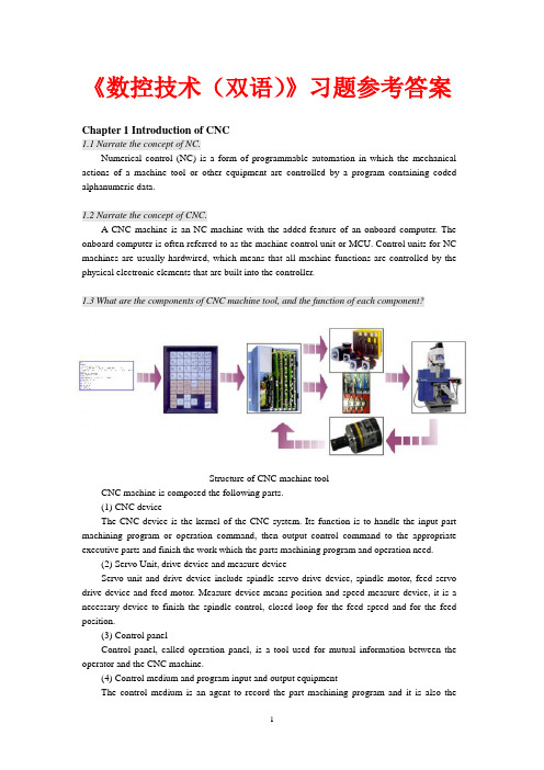
《数控技术(双语)》习题参考答案Chapter 1 Introduction of CNC1.1 Narrate the concept of NC.Numerical control (NC) is a form of programmable automation in which the mechanical actions of a machine tool or other equipment are controlled by a program containing coded alphanumeric data.1.2 Narrate the concept of CNC.A CNC machine is an NC machine with the added feature of an onboard computer. The onboard computer is often referred to as the machine control unit or MCU. Control units for NC machines are usually hardwired, which means that all machine functions are controlled by the physical electronic elements that are built into the controller.1.3 What are the components of CNC machine tool, and the function of each component?Structure of CNC machine toolCNC machine is composed the following parts.(1) CNC deviceThe CNC device is the kernel of the CNC system. Its function is to handle the input part machining program or operation command, then output control command to the appropriate executive parts and finish the work which the parts machining program and operation need.(2) Servo Unit, drive device and measure deviceServo unit and drive device include spindle servo drive device, spindle motor, feed servo drive device and feed motor. Measure device means position and speed measure device, it is a necessary device to finish the spindle control, closed-loop for the feed speed and for the feed position.(3) Control panelControl panel, called operation panel, is a tool used for mutual information between the operator and the CNC machine.(4) Control medium and program input and output equipmentThe control medium is an agent to record the part machining program and it is also themedium to set up contraction between man and machine. Program input and output equipment are the devices by which the information exchange can be done between the CNC system and external equipment. Its effect is to input the part machining program recorded on the control medium into the CNC system and to store or record the debugged part machining program on the appropriate medium with the output device.(5) Machine bodyThe object of CNC system is the executive part to fulfill the machining parts. It is composed of the main motion parts, feed motion parts, bearing rack and special device, automatic platform change system, automatic tool changer system and accessory device.1.4 What is the Point-to-point control, Contouring control?Point-to-point system, also called Positing control systems, moves the worktable to a programmed location without regard for the path taken to get to the location.The contouring facility enables a CNC machine to follow any path at any prescribed feed- rate. The contouring control system, also called continuous path control systems, manages the simultaneous motion of the cutting tool in two, three, four, or five axes (the fourth and fifth axes are angular orientations)by interpolating the proper path between prescribed points.1.5 What is the open-loop control, Half-closed-loop control and Closed-loop control?Open-loop systems have no access to the real time data about the performance of the system and therefore no immediate corrective action can be taken in case of system disturbance.A semi-closed-loop control CNC system uses feedback measurements to ensure that the worktable is moved to the desired position. It is characterized as a system that the indirect feedback monitors the output of servomotor.In a close loop system, feed back devices closely monitor the output and any disturbance will be corrected in the first instance.1.6 What are the advantages and disadvantages of CNC?CNC opens up new possibilities and advantages not offered by older NC machines.(1) Reduction in the hardware necessary to add a machine function. New functions can be programmed into the MCU as software.(2) The CNC program can be written, stored, and executed directly at the CNC machine.(3) Any portion of an entered CNC program can be played back and edited at will. Tool motions can be electronically displayed upon playback.(4) Many different CNC programs can be stored in the MCU.(5) Several CNC machines can be linked together to a main computer. Programs written via the main computer can be downloaded to any CNC machine in the network. This is known as direct numerical control or DNC.(6) Several DNC systems can also be networked to form a large distributive numerical control system.(7) The CNC program can be input from flash or floppy disks or downloaded from local area networks.CNC machines can dramatically boost productivity. The CNC manager, however, can only ensure such gains by first addressing several critical issues, such as the following:(1) Sufficient capital must be allocated for purchasing quality CNC equipment.(2) CNC equipment must be maintained on a regular basis by obtaining a full-service contract or by hiring an in-house technician.(3) Personnel must be thoroughly trained in the operation of CNC machines. In particular, many jobs require setups for machining parts to comply with tolerances of form and function.(4) Careful production planning must be studied because the hourly cost of operation of a CNC machine is usually higher than that for conventional machines.1.7 Narrate the financial rewards of CNC investment using Return on Investment.Return on investment (ROI) is used to estimate investment efficiency. The ROI calculation predicts what percent of the net cost of the CNC will be recovered each year. The ROI calculation accounts for the useful life of the CNC machine tool.Chapter 2 CNC Part Programming2.1 Read and match the picture to the name of the hand tool.[13] hacksaw[8] bench vise [2] file card [16] scraper [23] die[4] hand taps [25] hammer [12]burnishing tool[6] adjustable wrench [3] tap extractor。
数控技术应用专业英语LS5-3

Task , it has been held in China every 2 years ever since the first CIMT show existence in 1989. The show had been recognized as one of the four most important machine exhibitions in the world. 张 :不是,自从1989年的第一届中国国际机床展览会以 来,每两年在中国举行一次。该机床展览会被公认为世界四大 机床展览会之一。 Smith: I’m sure to come next time. 史密斯:下次我肯定还会来的。 Zhang: You are welcome! Let me show you around. 张 :欢迎,欢迎!我带你转转。 Smith: It’s very kind of you! 史密斯:你真是太好了!
Task 3 At CIMT Outside the Hall
Smith: What products will be shown on CIMT? 史密斯:CIMT展出哪些产品? Zhang: The scope of CIMT includes the following: machines, tools, measurement equipments, automation for the industry and CAD/CAM etc. 张:CIMT展出产品包括:机床、刀具、测量装置、工业 自动化和CAD/CAM等等。 Zhang: Look at those large balloons in the air with welcoming slogans on them. 张:看那些在空中飘扬的大气球,上面写着欢迎标语。 Smith: This is very impressive indeed. It seems to be a big show. 史密斯:真的让人印象深刻,看起来是一个大展会。
数控机床英语试题及答案

数控机床英语试题及答案一、选择题(每题2分,共20分)1. What is the abbreviation for "Computer Numerical Control"?A. CNCB. NCC. CADD. CAM2. Which of the following is not a CNC machine tool?A. LatheB. Milling machineC. Drilling machineD. Hand saw3. The primary function of a CNC system is to:A. Cut materialsB. Control the movement of the machine toolC. Design partsD. Operate the machine manually4. What does the term "G-code" refer to in CNC?A. Graphical codeB. Geometric codeC. General codeD. Group code5. In CNC machining, the term "feed rate" refers to:A. The speed of the cutting toolB. The rate at which the machine moves the workpieceC. The rate at which the machine changes the cutting toolD. The speed of the machine's spindle6. Which of the following is a common CNC programming language?A. JavaB. PythonC. M-codeD. C++7. What is the purpose of a tool changer in CNC machines?A. To improve the accuracy of the machineB. To increase the efficiency of the machining processC. To reduce the cost of the machineD. To decrease the size of the machine8. The term "machining center" refers to a CNC machine that:A. Can only perform milling operationsB. Can perform a variety of machining operationsC. Is located at the center of a workshopD. Is the most expensive type of CNC machine9. What does the "Z-axis" represent in CNC machines?A. The horizontal movement of the cutting toolB. The vertical movement of the cutting toolC. The rotational movement of the workpieceD. The linear movement of the workpiece10. The main advantage of CNC machines over traditional machines is:A. Lower costB. Greater flexibility and precisionC. Easier operationD. Smaller size二、填空题(每题2分,共20分)1. The CNC machine tool is controlled by a ________ that interprets the programmed instructions.2. The ________ axis in CNC machines is responsible for the rotational movement of the workpiece.3. A CNC machine can perform complex operations with high________ and ________.4. The ________ is a set of rules that defines the movement and actions of the CNC machine.5. CNC machines are widely used in industries such as automotive, aerospace, and ________.6. The ________ is the part of the CNC machine that holds the cutting tool.7. In CNC programming, the ________ command is used to specify the path of the cutting tool.8. The ________ is a device that translates the programmed instructions into machine movements.9. The ________ is the process of creating a part by removing material from a workpiece.10. CNC machines can be programmed manually or through the use of ________ software.三、简答题(每题10分,共20分)1. Explain the difference between a CNC lathe and a CNC milling machine.2. Describe the basic components of a CNC machine and theirfunctions.四、论述题(每题15分,共30分)1. Discuss the importance of CNC machines in modern manufacturing and their impact on productivity and quality.2. Analyze the role of CNC programming in the operation of CNC machines and the skills required for effective CNC programming.五、翻译题(每题5分,共10分)1. 翻译以下句子:"CNC machines have revolutionized the way parts are manufactured."2. 翻译以下句子:"The CNC programmer must ensure that the program is error-free before running it on the machine."答案:一、选择题1-5 A D B C B6-10 C B B B B二、填空题1. computer program2. C-axis3. precision, efficiency4. G-code5. electronics6. tool holder7. G8. control unit9. machining10. CAD/CAM三、简答题1. A CNC lathe is designed for turning operations, which involve rotating the workpiece and cutting from the exterior.A CNC milling machine, on the other hand, is used for milling operations, which involve moving the cutting tool in various directions to remove material from the workpiece.2. The basic components of a CNC machine include the control unit, which interprets and executes the program; the drive system,。
- 1、下载文档前请自行甄别文档内容的完整性,平台不提供额外的编辑、内容补充、找答案等附加服务。
- 2、"仅部分预览"的文档,不可在线预览部分如存在完整性等问题,可反馈申请退款(可完整预览的文档不适用该条件!)。
- 3、如文档侵犯您的权益,请联系客服反馈,我们会尽快为您处理(人工客服工作时间:9:00-18:30)。
Journal of Cleaner ProductionVolume 137, 20 November 2016, Pages 361–369Analytical approach to establishment of predictivemodels of power consumption of machine tools' auxiliary units∙Machine tool;∙Energy model;∙Energy consumption;∙EcodesignThe issue of production machine energy consumption has been recently gaining prominence, particularly due to the efforts made by the developed countries to reduce the impact of human activity on the environment. Since the operation of production machines is very energy-demanding, it is during their operation that production machines contribute to damaging the environment the most, as shown by previous studies (CECIMO, 2009). Rising energy prices together with efforts to reduce manufacturing costs have resulted in machine tool users request for minimizing energy demands of manufacturing. This pressure on production machine producers is further increased by the EU directive on reducing energy demands in all areas of human activity, in particular in industrial production, where production machines are significant energy consumers (European Union, 2009). In order to meet the objective of reducing production machine energy demands, it is necessary to consider potential energy savings already during the design stage of these machines or when planning production on these machines. Simulation of energy consumption during the design phase of the machine or technology can be an advantage giving an overview on costs of planned production which is nowadays one of the current issues. This cannot be achieved without the application of predictive models of energy consumption. A large part of studies and models that have been carried out so far focuses in particular on predicting the consumption of drives. However, the contribution of auxiliary units to total energy consumption is significant and often higher (Holkup et al., 2013). Therefore, it is necessary to deal with them in further development of energy consumption predictive models systematically and to give them the attention they deserve.1.1. State of the artDraganescu et al (Draganescu et al., 2003). studied the influence of cutting conditions on machine tool efficiency and power consumption. They searched for a mutual relationship between these two parameters based on practical tests. Weinert et al (Weinert et al., 2004). focused on the possibilities of reducing the amount of cutting fluid used during machining, which is one of the methods of reducing manufacturing costs. Although they did not examine the effect on energy consumption directly, they are often mentioned since their research made it possible to increase cutting speeds. This allowed reduction in manufacturing time, an essential parameter affecting machine tool consumption. Rangarajan and Dornfeld (Rangarajan and Dornfeld, 2004) were also aware of the significant role operating times play in reducing energy consumption. They focused on the optimization of cutting tool paths duringmachining. They also investigated the influence of workpiece clamping orientation on total time of machining planar surfaces. Gutowski et al (Gutowski et al., 2006). were the first to apply an exergic approach to energy consumption of manufacturing processes (exergy measures the potential of materials to do work). Based on this approach, Gutowski created a simple model of machine tool power consumption (1). This model is based on the simplistic assumption that the consumption of auxiliary units is independent of the machining process. Using tests, he also discovered that the consumption of these units may approximately constitute up to 85% of total machine tool energy consumption.equation(1)Turn MathJaxonwhere E [Ws] is the total energy consumed by the machine tool, P0 [W] is the idle power, k[Wsm−3] is the specific cutting process energy, [m3s] is the material removal rate and t[s] is total machining time.This research was followed by Diaz et al. (Diaz et al., 2011), who focused on identification of relationships between cutting conditions represented by material removal rate, active power requirement and total energy consumption. Kara and Li (Kara and Li, 2011) brought new insights into energy consumption of production machines. They considered the machine as a holistic system, which is able to influence its subsections. Therefore, it is necessary to deal with the relationships between these subsections as it is no longer possible to strictly divide energy consumption between the cutting process and auxiliary units as has been the practice so far. Mori et al (Mori et al., 2011). focused on the possibilities of energy savings using enhanced acceleration and deceleration control with added synchronisation of the spindle with feed axes. Their improved model included power demand for the spindle to accelerate or decelerate. Mativenga and Rajemi (Mativenga and Rajemi, 2011) focused on the selection of optimum cutting conditions with respect to cutting tool lifetime. This initiated a discussion on power consumption during tool exchange. Li and Yan (Li et al., 2013) dealt with modelling machine tool energy consumption and established a refined empirical model of machine tool active power, which achieves significantly more accurate results in comparison with predictive models of their predecessors. In their further research, they looked at multicriterial optimization of cutting conditions as a search for a compromise between material removal rate, power consumption and surface quality (Yan and Li, 2013). Avram and Xirouchakis (Avram and Xirouchakis, 2011) focusedon predictive models of energy consumption using NC code analysis. A similar sophisticated model (2) was also developed by He et al. (He et al., 2012). equation(2)Et o t a l =Es p i n d l e+Ef e e d+Et o o l+Ec o o l+Ef i xTurn MathJaxonwhere E total [Ws] is the total direct requirements, E spindle [Ws] is spindle energy requirements for the main cutting motion, E feed [Ws] is feed axes requirements for secondary cutting motions, E tool [Ws] is tool exchange energy requirements, E cool [Ws] is energy of cutting process cooling and E fix [Ws] is machine energy requirements.The research of the above-mentioned authors was further continued by Balogun and Mativenga (Balogun and Mativenga, 2013) and Dietmair and Verl (Dietmair and Verl, 2009), who developed own advanced models of energy consumption. These models use a division of the entire working cycle according to machine regimes. Witt et al (Witt et al., 2014). developed simulation software for real-time energy consumption and manufacturing cost predictions. This software is capable of providing valuable information already in the production planning phase. It uses data from a real control system (hardware in the loop) for the prediction of energy consumption of drives. As many other authors, they are confronted with the issue of determining the consumption of a substantial part of auxiliary units, which significantly contribute to the total consumption of a machine tool.The analysis of existing machine tool energy models leads to conclusion that consumption of auxiliary units can be higher than consumption of drives. Unfortunately not so many researchers have been interested in the precise modelling of energy consumption of machine tools auxiliary units yet. Therefore this part of the simulation should be investigated in more details.1.2. Research aim and scopeThis paper proposes an analytical approach to the establishment of predictive models of power consumption of machine tools' auxiliary units. An estimation of power consumption of auxiliary units acquired by the model described below together with the consumption of drives. Drives can be predicted using the already published models and it will provide machine tool users with insights into total energy demands during production. The main objective of using this analytical approach is an increasing of the conformity between the consumption predicted by the model and the actual consumption of a machine tool.2. Method of modellingIn this chapter a creation process of energy models of machine tools especially of their auxiliary units will be described.2.1. Model establishmentThe evaluation of the proposed model (see Fig. 1) can be described in the following three steps:Step 1. Analysis of all installed machine auxiliary units and theirbehaviour.Step 2. Establishment of submodels of analyzed auxiliary units.Step 3. Sum of energy flows of all auxiliary units, including theconsumption of compressed air and drives.Fig. 1.Model of machine tool energy consumption.Figure options2.2. Core of modelThe core of the established model may be mathematically described by three basic equations. They express the relationship between the active power of the device and its activity (3), the above-mentioned summation of energy flows (4) and subsequent calculation of the energy consumed (5).equation(3)Pi (t)=A(t)·Pi n p u tTurn MathJaxonwhere P i (t) [W] is the time characteristic of the active power of a given auxiliary unit, A(t) [−] is the time characteristic of activity of a given auxiliary unit and P input [W] is the required active power of a given auxiliary unit in normal operation.equation(4)Turn MathJaxonwhere P total (t) [W] is the time characteristic of total active power of the machine, P drive (t) [W] is the time characteristic of active power of machinedrives, P air (t) [W] is the time characteristic of equivalent active power of auxiliary units powered by compressed air (see Eq. (6)) and P i (t) [W] is the time characteristic of active power of individual auxiliary units included in the model.equation(5)Turn MathJaxonwhere E total [Ws] is total consumed energy of the machine, P total (t) [W] is the time characteristic of total active power of the machine, T [s] is totalsimulation time, is the vector of machine active powers and is thevector of simulation time increments.The complexity of the model is dependent on the number of auxiliary units included in the model. It is also dependent on their selected main properties and their energy behaviour.2.3. Auxiliary units categorizationThe auxiliary units is possible classify according to the following basic criteria. Criterion 1 – mode of operationThe mode of operation is mainly influenced by time parameters that are entered into appropriate submodels. Based on this criterion, the following types of auxiliary units are distinguished (see Fig. 2).Fig. 2.Classification of auxiliary units based on mode of operation.Criterion 2 – autonomy of auxiliary units behaviourThe autonomy of auxiliary units control is an important factor, which is an expression of the relationship between the control system of the machine and the controlled auxiliary unit. This key property of auxiliary units influences the possibility of predicting their activity based on knowledge of machine control system commands. Based on the autonomy of control, auxiliary units can be divided into three groups (see Fig. 3).Fig. 3.Classification of auxiliary units based on the autonomy of their control.Figure options Non-autonomous auxiliary units are controlled directly by the machine control system and have no other regulation that would influence their operation and active power. Semi-autonomous auxiliary units are operated by the machine control system and they have their own autonomous regulation, which influences their activity. Fully-autonomous auxiliary units are not controlled by the machine control system and are completely independent on it.Criterion 3 – type of performance controlThe type of performance control of auxiliary units is the next criterion directly influences the complexity of submodels and thus in particular input performance parameters. The following types of auxiliary units control are significant (see Fig. 4). Auxiliary units with one-level control only operate in ON/OFF regime, whereas auxiliary units with discrete multi-level control operate on several discrete performance levels. Auxiliary units with continuous control can work in all performance level of the entire range.Fig. 4.Classification of auxiliary units based on the type of performance control.Figure optionsCriterion 4 – type of operation initializationThe mode of operation initialization of auxiliary units significantly influences the ability to predict their activity in advance. Based on this criterion, the following basic types of auxiliary units initialization can be distinguished:AUTO The characteristic of activity of auxiliary units with automatic operation initialization is determined by the machine producer and their behaviour cannot be influenced by the machine user (for example electric cabinet air conditioning). The activity of auxiliary units can be predicted only based on a thorough knowledge of the PLC programme.SEMI Auxiliary units with semi-automatic operation initialization are initialized by the NC programme (for example tool edge cooling). Their activity can be predicted based on the NC programme analysis.MAN Auxiliary units with manual operation initialization are initialized manually by a machine operator using the control panel. The characteristic of their activity is very difficult to predict or they are completely unpredictable.2.4. Acquiring submodel input parametersClassification of auxiliary units based on the above-mentioned criteria has a significant impact on the complexity of submodels and their performance parameters. These parameters may be determined in two ways, i.e. directly without measuring on the machine and indirectly by measuring on the machine.Time parameters and some performance parameters that may be determined directly without measuring on the machine. Time parameters may be acquired for example by a time analysis of the NC programme. Some performance parameters may be obtained in the same manner although the model established in this manner may provide very rough results (the upper limit of consumption). It is primarily performance parameters of individual auxiliary units that are determined indirectly by measuring on the machine. Using parameters obtained by measuring on a specific machine tool, relatively accurate results of energy consumption calculation are obtained.2.5. Submodels of selected auxiliary unitsA typical representative of auxiliary units that are difficult to simulate are air conditioning of an electrical cabinet of a machine tool. These auxiliary units usually belong to automatically operated devices with own autonomous regulation. Performed measurements (see Fig. 5) showed that at the beginning of the machine operation the period between the activation of the air conditioning became gradually shorter due to rising temperature of elements in the electrical cabinet. Later, the number of activations became stable, which is caused by stabilization of temperature in the electrical cabinet. It can be assumed that unless there is a dramatic change in machine tool load or ambient conditions, the air-conditioning unit will continue to be activated in this periodic manner.Fig. 5.Time characteristic of active power of electrical cabinet cooling unit.Figure options These auxiliary units are usually replaced by an average value in models, so called “simple-submodel”. In case of long-term simulation the difference between model and reality can be neglected. For middle-term simulation it is more appropriate to select an enhanced submodel (combined-submodel of a permanently working and periodically started device). This enhancedsubmodel provides a higher degree of compliance with more negligible error in comparison with a simple-submodel.The combined-submodels may be also used for example in modelling machine tool fluid systems. This is evident from the active power measuring of auxiliary units on the three axis milling machine (see Fig. 6). The fluid systems for coolant comprise of a complex set of pumps. The main pump works continuously from its initialization by an appropriate M function in the NC programme, whereas the transfer pump is initialized discontinuously depending on the drop of fluid level in the tank.Fig. 6.Time characteristic of active power of selected machine tool auxiliary units.Figure options Another type of submodel is a division of the total operation of a selected auxiliary unit into two and more sections (run-up and operation). This type of submodel is for instance applicable to the unit responsible for sucking vapour from the workspace as shown by the same measurement performed on the three axis milling machine (see Fig. 6). Measurements revealed that active power during the run-up of this unit is approximately double the normal operation active power and the run-up itself takes approximately from 3 to 5 s. Apart from electric appliances, it is also necessary to consider the electric equivalent of air consumption according the equation (6) (Holkup et al., 2013). equation(6)Pa i r (t)=c·Qa i r(t)Turn MathJaxonwhere P air (t) [W] is the time characteristic of equivalent active power of auxiliary units powered by compressed air, c [Wdm−3min] is the conversion ratio between compressor active power and flow of air into the machine for a given compressed air distribution system and Q air(t) [dm3min−1] is the timecharacteristic of flow of compressed air into given auxiliary units in the machine.Using this calculation of compressed air equivalent active power (6) is possible to improve any standard models they do not account with this like (1) and (2).As shown by the measurement results (see Fig. 7), compressed air consumption in this specific case is a typical area where it is possible to replace the measured characteristic by the average value for the calculation of consumption. This is due to the fact that in 80% of the monitored characteristic the value of average and real compressed air flow differs approximately only by 10%. However, it depends on the specific type of machine and the number of installed auxiliary units powered by air as well as on the quality of elements used and compressed air distribution with respect to leakage. Last but not least, the machine working regime is important as well.Fig. 7.Time characteristic of compressed air flow into the machine.Figure options3. Experiment proposalAn experiment was proposed in order to compare the accuracy of the model of machine tool auxiliary units energy consumption and measurements on a real machine. The experiment was performed on the three axis horizontal milling machine (see Fig. 8 and Table 1).Table options•external cooling of cutting tool (M8).•flushing chips from workspace (M20, M22).•lubricating unit.Fig. 10.Time characteristic of total active power of machine tool auxiliary units (uncalibratedmodel).Figure optionsFig. 11.Time characteristic of total energy consumed by machine tool auxiliary units(uncalibrated model).Figure options Therefore, it is necessary to perform a simple calibration of real energy consumption of all auxiliary units used for the model. Each unit is measured separately and real consumption is monitored. This simple calibration resulted in greater accuracy of input performance parameters of monitored auxiliary units submodels. These calibrated data are than used to make a verification measurement with the proposed model.4.2. Model verificationThis calibration led to greater accuracy of the calculation of the total energy consumed as shown in Fig. 12 and Fig. 13. The error of the model is now around 12 % during the whole simulation period. This difference is caused by unknown energy consumer activity during the last phase of the measuring. Incase of simulation of all known consumers in ti me 0 to 700 s, the accuracy of the model is around 1 %. This difference is discussed in the next chapter.Fig. 12.Time characteristic of total active power of machine tool auxiliary units (calibratedmodel).Figure optionsFig. 13.Time characteristic of total energy consumed by machine tool auxiliary units(calibrated model).Figure options4.3. DiscussionClear error that is noticeable from the comparison of real and predicted machine tool active power is the activity of an unidentified auxiliary unit in the time section from 700 to 720 s. An error of the model relative to the measurements arose during the activity of this auxiliary unit. The relative deviation of the modelled consumption in comparison to the measured consumption was 1 % until this moment in time. However, it rose to final 12 % due to the activity of the unidentified auxiliary unit. This situation shows the necessity to know all energy consumers and account with them in the modeleven if it looks like negligible from the point of view actual power input. The overall energy consumption calculation can be significantly affected.Another small error is evident from the time characteristic of total active power of the monitored group of auxiliary units. The model contains errors in the time offset of initialization of given auxiliary units. In this case, these errors are caused by the method of NC code analysis, which failed to take into account transfer delays in initializing individual auxiliary units. These errors may be suppressed by using real or simulated control systems (e.g. virtual iTNC). However, the impact on total consumed energy in the performed test is minimal (see Fig. 13).5. ConclusionsThe functionality of the simple model was proved. The performed tests showed the great significance of a thorough identification of all auxiliary units contributing to energy consumption. This accurate identification of machine tool auxiliary units is an important factor affecting the resultant accuracy of the model of the entire machine tool. The necessary step is to calibrate the real consumption of tested units and devices because the plates parameters and real situation can be quite different. Without this calibration, the accuracy of the modelling is not good.The next issue for the modelling is to have a proper time line for the activation of tested devices. Therefore, the next step would be using the virtual control system with the real PLC setting to cover drives performance such as real positioning and speed control loops. Due to this model improvement, a better time line of the machining and auxiliary unit initialization can be achieved to make a more accurate simulation of energy consumption.AcknowledgementThe paper has received funding from the Technology Agency of the Czech Republic。