S100说明书
金松S100系列说明书.doc02

深圳希望金松变频技有限公司
地址:深圳市沙井新区恒明珠科技工业区 11 栋 电话:0755-27832510 传真:0755-29497582 全国统一服务热线: 400-627-0809
择
DI5 COM
DO COM
多功能双极性 开路集电极输
出端子
+10V
AI AI
IV
GND
TA 继电器1 TC 输出 TB
TA1 继电器2输 TC1 出(预留) TB1
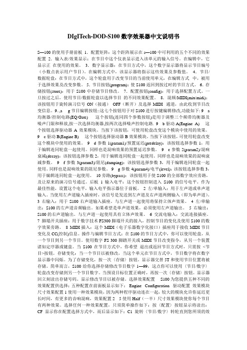
1.7.2 控制回路端子布局图
图 1-7 控制回路及主回路接线图
产品信息
图 1-8 金松 JS100 系列控制回路端子图
1.7.3 控制回路端子说明
1.7.4 控制回路跳线说明
跳线名称 AI AO 485 J3
功能说明
AI电压、电流输入模式选择 AO电压、电流输出模式选择 通讯一台OFF,多台并联选ON
主板接地选择
出厂设定 V V
OFF OFF
金松 JS100 系列简易型矢量变频器使用说明
8
功能参数表
第二章 功能参数表
F7-29 设为非 0 值,即设置了参数保护密码,在功能参数模式和用户更改参数模式下,参数菜单必须在正确 输入密码后才能进入,取消密码,需将 F7-29 设为 0。
金松 JS100 系列简易型矢量变频器使用说明
3
1.1 命名规则
第一章 产品信息
产品信息
1.2 铭牌
图 1-1 命名规则
云图车联网S100说明书

云图车联网S100说明书产品定义S100是专门针对物流车和工程车而开发的一款远程车载智能终端设备。
S100集成了GSM/GPRS模块、高精度GPS模块、高性能三轴重力传感器和车载ECU电脑通信模块,可以将车辆运行状态、车况数据、车辆故障诊断数据、驾驶者操控数据等通过GSM模块上传至车联网管理云平台。
车联网管理云平台将这些数据进行深度挖掘,为企业车辆的运营管理、远程调度、在途监管、安全用车等应用服务提供全方位解决方案。
产品结构产品外观产品功能a)、支持即插即用b)、支持车型广泛c)、具有内部总线的车辆,采用总线感应器方式,不破坏汽车原有线路,采集汽车内部总线上的和车辆运行相关的数据。
总线感应方式获取国家发明专利。
d)、车辆定位和轨迹跟踪e)、车机与车辆通讯f)、设备支持低功耗休眠和唤醒方式g)、精准里程和精准油耗统计h)、车辆实时车况监测i)、多种报警提醒功能:点火报警、熄火报警、车辆低电压报警、怠速过长报警、超速报警、疲劳驾驶报警、设备插入报警、设备拔出报警、水温报警、定位时间过长报警、高速空档滑行报警、急加速报警、急减速报警、急转弯等等。
j)、驾驶行为分析:急加速、急减速、急转弯、超速、疲劳驾驶、空档滑行、非经济驾驶等等k)、事件统计及上报功能:驾驶行为事件、超速事件、怠速事件、非经济驾驶事件、空档滑行事件等等。
l)、集成RFID射频设备模块,实现出勤、换班打卡功能。
m)、提供串口与车机设备进行数据通讯。
n)、设备数据支持透传给采集处理平台。
o)、集成车载终端系统,支持系统远程升级。
p)、支持远程参数设置与查询功能,比如:告警相关参数、数据透传上报频率等。
q)、设备可扩展性强。
LS电子标准AC驱动S100说明书

S1000.4~2.2kW(0.5~3HP) 1-Phase 200~240Volts0.4~15kW(0.5~20HP) 3-Phase 200~240Volts0.4~75kW(0.5~100HP) 3-Phase 380~480VoltsIP66 NEMA4X 0.4~2.2kW(0.5~3HP) 1-phase 200V~240VoltsIP66 NEMA4X 0.4~15kW(0.5~20HP) 3-Phase 200~240VoltsIP66 NEMA4X 0.4~22kW(0.5~30HP) 3-Phase 380~480Volts2C o n t e n t s0410121417212832S100 Features IP66/NEMA 4X Model and Type SpecificationsWiring / Terminal Configuration Keypad Functions Peripheral Devices DimensionsPowerful sensorless control, and a diverse range of user friendly functions delivers added value to our customers.Meet the new standard drive S100 by LS for the global market.Strong Power with a Compact Size !S10 0High-performanceStandard Drive3High-performance Standard Drive• Built-in safe torque off (STO) • Redundant input circuitSafetyFunctions • Sensorless control functions• Starting torque (200%/0.5Hz)Strong Performance• Side-by-side installation • Decreased dimensions Space EfficientDesign • Various field networksSuitable for Users• Built-in EMC filter • International standardsStandard ComplianceScan the QR code on your drive front and check the key use information4Specialized FeaturesS100 Improves User Convenience with Smart Copier .Drive Control PartDrive Input/Output Part (Flash Memory)Auto-synchronization When Power-onSmart Copier Receives From Drive Input/Output PartSmart Copier Sends to Drive Input/Output PartRead Parameter Memory Write Parameter MemorySmart CopierSmart Copier Flow ChartThe drive does not need to be powered when using the smart copier.Functions Without Power InputI/O input and output can be shared among master and slave drive (RS485 wiring required)P2P Function EmbeddedThe run LED flickers during normal operation. The error LED flickers when events such as communication errors occur.LED Lamp FeedbacksParameters can be copied/loaded from the drive to the smart copier and vise versa,simply with the keypad.Read / Write Function of ParametersMultiple drives can be controlled and monitored with single keypad. (RS485 wiring required)Multi Keypad FunctionParameters saved in the smart copier can be down-loaded to both the drive I/O and the control part.Simple InstallationSimple PLC sequences can be operated with various function block combinations.User Sequence FunctionUser ConvenienceRJ45(Included if Smart Copiers are Purchased)Smart CopierGraphic LCD can be used for parameter copy from drive to drive.6Suitable for UsersS100 Offers a Variety of Customer Conveniencesto Compete in the Global Market.① Profibus-DP ④ CANopen ② Ethernet IP ⑤ EtherCAT ③ Modbus TCP⑥ PROFInet[Various Field Bus Options]Various Field Bus Options Easy to Install and Use.Conduit Kit Acquired UL open type & enclosed type1 certification※ UL open type is offered as default※ UL enclosed type1 needs conduit kit(option) installationThe heat sink can be mounted outside of the panel in case the space is limited.Flange Type• Relay output: 2ea (NO/NC selectable)• Digital input: 3ea (NPN/PNP selectable)• Analog I/O: 2ea/1ea eachExtension I/O Option CardPossible to connect to a variety of fieldbus networks Easy maintenance and mountingSimple Cooling Fan ReplacementReplaceable fan without complete disassemblyMasterSlave2Slave1※ LCD keypad (same as iS7 model) enables handy parameter set up.※ Multi language support will be available.Multi-Keypad FunctionSingle LCD keypad can be used to set up the parameters of a RS485 connected drives.Parameter Change with a Keypad.7High-performance Standard DriveDriveView9 Connection with RJ45 PortiS7 Normal CableRJ45 to USB Cable* RJ45 to USB Cable : Available as option8Space Efficient DesignS100 Increases Efficiency of the Control Panel.50mm50mm2mm2mm50mm 50mm50mm50mmiG5A (500mm) S100 (404mm) Minimized distance between drives enables panel size reduction for multiple drives installation.Side-by-side InstallationMain components have been optimally designedthrough thermal analysis and 3D design to reducethe dimension up to 60% compared to iG5A.Smaller SizeHDWSize Reduction60%400V 11kW Basis9High-performance Standard DriveStandard ComplianceS100 Has Built-in Safety Functions Suitable for Modern Safety Standards.※ Safety relay needs to be purchased separately.Main PowerSafety RelaySC 24VSA SBGate BlockMControl Circuit• Meets the electrical noise reduction regulation.• Related standards: 2nd Environment/Category C3(Class A) - CE standard is certified※ 1-phase 200V 0.4~2.2kW (C2) / 3-phase 400V 0.4~45kW (C3]Designed to be used for heavy and normal duty applications.• Overload capacity - H eavy duty operation: 150% of rated current, 60 seconds - Normal duty operation: 120% of rated current, 60 seconds※ Excludes IP66/NEMA 4XDual Rating OperationThe Safety input function meets EN ISO 13849-1 PLd and EN 61508 SIL2 (EN60204-1, stop category 0).This feature is standard and enables compliance with current safety standards.Built-in Safe Torque Off(STO)Built-in EMC FilterEffective in improving power factor and decreasing THD.※ 3-phase 400V 30~75kWBuilt-in DC ReactorRedundant Input CircuitStandstill or rotary auto-tuning options are available as standard to find motor constants with or without rotating the motor for optimized motor performance.Selectable Rotary / Standstill Auto-tuningGlobal standard complianceGlobal Compliance10High-performance Standard DriveS100 IP66/NEMA 4X SeriesProtected Against Foreign Substances Such as Fine Dust and High Pressure Water Spray.• Satisfies NEMA standard type 4X for indoor use.• Satisfies IEC 60529 standard IP66•1Ø 200V 0.4~2.2kW / 3Ø 200V 0.4~15kW / 3Ø 400V 0.4~22kW • PDS / Non-PDS (PDS; Power Disconnect Switch)The Drive for Harsh Ambient Conditions.IP66 / N EMA 4X※ (F): Built-in EMC or Non-EMC type selectable ※ 55~75kW satisfies EMC class 3* For the rated capacity, 200 and 400V class input capacities are based on 220 and 440V, respectively.* The rated output current is limited depending on the setup of carrier frequency (CN-04).* The output voltage becomes 20~40% lower during no-load operations to protect the drive from the impact of the motor closing and opening (0.4~4.0kW models only). * Dual rating is supported except IP66/NEMA 4X* For the rated capacity, 200 and 400V class input capacities are based on 220 and 440V, respectively.* The rated output current is limited depending on the setup of carrier frequency (CN-04).* The output voltage becomes 20~40% lower during no-load operations to protect the drive from the impact of the motor closing and opening (0.4~4.0kW models only). * Dual rating is supported except IP66/NEMA 4Xequest saLes peRson FoR ensoRLess FunctionDC InputShort Bar2) Use copper wires with 600V, 75°C specification.connected .DC ReactorBraking ResistorR(L1)S(L2)T(L3)P1(+)P2(+)BN(-)U V WR(L1)S(L2)T(L3)P2(+)P3(+)N(-)U V WDC InputBraking Unit1)2) Standard I/O is only provided for P5.3) In case of Standard I/O, Pulse input TI and multi-function terminal P5 share the same terminal. Set the ln.69 P5 define to 54(TI).4) In case of Standard I/O, Pulse output TO and multi-function output Q1 share the same terminal. Set the OU.33Q1 define to 38(TO).S+S-SG VR V1CM I2AO P5P6P7CM SA SB SC TO A1B1C1Q1EG24P1P2P3P4TIS+S-SG VR V1CM I2AOP4P5CM SA SB SC A1B1C1Q1EG24P1P2P30.4~22kW30~75kW0.4~22kWStandard I/OMultiple I/OStandard I/O※ LSLV-S100 can be supplied with either standard I/O or multiple I/O※ I/O board is supplied built in. IS7 LCD loader can be mounted on the front of the drive. ※ NC: Terminal not in use.DisplayFWD during acceleration/deceleration)operationSETLearning how to operate a S100(Smart device with android)2) Visible only when setting the function item of In.65~71 multi-function input terminal as no.26(2nd motor).1) Indicates only the target frequency when LCD keypad is installed. The first code of the operation group is a place to set a target frequency. It had been set as 0.00 when shipping fromthe factory, however, if a user changes the operating frequency, it indicates the changed operating frequency.2) Visible only when setting the function item of In.65~71 multi-function input terminal as no.26(2nd motor).Therefore, an over current trip (OCT) or over voltage trip (OVT) may occur when there is a low-resistance ground fault.1)If you do not want to enter the modified value, you can press the left, right, up or down keys (◀) (▶) (▲) (▼) except the enter key (ENT) in the ON condition to cancel the input.calculated at twice the standard.• The resistance/rated capacity/braking torque/%ED of DB Resistor are valid only for the DB unit of type A and the values of DB Resistor for type B and C refer to the manual of DB Unit..• Rating Watt of DBU has to be doubled when %ED is doubled.• It is not necessary to use option type dynamic braking unit for S100 below 22kW capacity because basically the dynamic braking unit is built in.• You must refer to dynamic braking unit manual for usage recommended dynamic braking unit in the table above due to changeable table.Terminal ArrangementGroup 1Group 3Group 2 :Group 4, 5braking unit.LSLV0022S100-1 / 0037S100-2 / 0037S100-4 / 0040S100-2 / 0040S100-4LSLV0004S100-1 / 0004S100-4 / 0008S100-4 (Built-in EMC)LSLV0008S100-1 / 0015S100-1 / 0015S100-4 / 0022S100-4 (Built-in EMC)LSLV0022S100-1 / 0037S100-4 / 0040S100-4 (Built-in EMC)LSLV0055S100-2 / 0075S100-2 / 0055S100-4 / 0075S100-4LSLV0110S100-2 / 0110S100-4 / 0150S100-4LSLV0150S100-2 / 0185S100-4 / 0220S100-4LSLV0300S100-4LSLV0370S100-4 / 0450S100-4LSLV0550S100-4 / 0750S100-4IP66(NEMA4X) 0.4~4.0kWIP66(NEMA4X) 5.5~7.5kWIP66(NEMA4X) 11~22kWCommunication Option Module (Installation Example)Conduit OptionConduit Option1) eMc LteRBuiLt-in c La※c onduit s ize:1/2inches(Ø:22.3MM),3/4inches(Ø:28.6 MM) 1 inches (Ø : 35 MM), 1+1/4 inches (Ø : 44.5 MM)1) eMc LteRBuiLt-in c Lass3 ※c onduit s ize:1/2inches(Ø:22.3MM),1+1/4inches(Ø:44.5MM) 1+1/2 inches (Ø : 50.8 MM), 2 inches (Ø : 63.5 MM)Flange OptionFlange OptionFlange Option。
S100说明书
DIgITech-DOD-S100数字效果器中文说明书S—100的使用手册前板1.配置矩阵:这个距阵展示在s—100中可利用的五个不同的效果配置2.输入表/效果显示:在节目中这个仪表显示进入该单元的输入信号。
在编辑中,它显示正在使用的效果。
3.数字显示器:在节目方式中,这个数字显示器将显示节目编号(小数点表示用户节目)。
在编辑方式中,该显示器将指示这些效果及参数值。
4.节目/数据轮盘:在节目方式中,这个轮盘用于改变节目的当前使用单元,在编辑方式中,被用于选择效果及改变参数。
5.节目按钮(program):使S100返回到按过时的节目方式。
6.存储按钮(store):用于S100中存储节目修改。
7.配置按钮(config):用于选择配置方式。
一旦按过之后,使用节目/数据轮盘以选择节目的不同效果配置。
8.混频/MIDI(mix/midi):该按钮用于旋转演习信号ON(接通)OFF(断开)及选择MIDI 通道,由此收到节目改变信息。
9.,a----g节目编辑按钮::这七个按钮用于对S100进行按键编辑修改,功能如下: 9---a 均衡器/控制电路(EQ/Gate)-----这个按钮(连同四个参数按钮)是用于调整三个频带均衡器及噪声门限和释放,按一次选择均衡器,按两次选择噪声控制电路. 9---b驱动A(Engine A)----这个按钮选择驱动器A效果模块。
当按下该按钮,可使用轮盘改变这个模块中使用的效果。
9---c驱动B(Engine B)----这个按钮选择驱动器B效果模块。
当按下该按钮,可使用轮盘改变这个模块中使用的效果。
9---d参数1(param1)/预置延迟(predelay):该按钮选择参数1,用于编辑连同轮盘一起使用。
同样也是混响效果的预置延迟参数。
9---e参数2(param2)/混响衰减(decay):该按钮选择参数2,用于编辑连同轮盘一起使用。
同样也是混响效果的混响衰减参数。
9---f参数3(param3)/阻尼(damping):该按钮选择参数3,用于编辑连同轮盘一起使用。
霍尼韦尔 S10010 S20010 A使用说明书

® U.S. Registered TrademarkEN0B-0463GE51 R0418Copyright © 2018 Honeywell Inc. • All rights reservedS10010 / S20010SPRING RETURN DIRECT-COUPLED DAMPER ACTUATORS10/20 Nm (88/177 lb-in) FOR MODULATING AND FLOATING CONTROLPRODUCT DATAGENERALThese direct-coupled damper actuators provide modulating / floating control for: ∙ air dampers, ∙ VAV units, ∙ air handlers, ∙ ventilation flaps, ∙ louvers, and∙ reliable control for air damper applications with up to1.5 m 2 / 16 sq.ft (10 Nm / 88 lb-in) or 4.6 m 2 / 50 sq.ft. (20 Nm / 177 lb-in) (seal-less dampers; air friction-dependent).FEATURES∙ Self-centering shaft adapter ∙ Removable access cover∙ Mechanical end limits (non-adjustable)∙Rotation direction selectable by choice of mounting orientation∙ Mountable in any orientation (IP54 only whenmounted on a horizontal shaft with access cover below the shaft)∙ Mechanical position indicatorSPECIFICATIONSSupply voltage S10010 / S20010 24 VAC ±20% / 24 VDC, 50/60 Hz Nominal voltage S10010 / S20010 24 VAC / 24 VDC, 50/60 Hz All values stated hereinafter apply to operation under nominal voltage conditions. Power consumption Holding Driving S10010 5 VA / 5 W 14 VA S20010 5 VA / 5 W 16 VA Ambient limitsAmbient operating limits -40...+60 ︒C Ambient storage limits -40...+70 ︒C Relative humidity 5...95%, non-condensing SafetyProtection standard IP54 Overvoltage category III Lifetime Full strokes 60000 Repositions 1.5 million Full stroke spring return 60000 MountingRound damper shaft 10...27 mm Square damper shaft 13...19 mm Shaft length 25 mm End switch (when included) Rating 5 A (resistive) / 3 A (induct.) Triggering points 7︒ / 85︒ Torque rating S10010 10 Nm (88 lb-in) S20010 20 Nm (177 lb-in) Runtime 90 sec (50 Hz) Spring return timing 20 sec (50 Hz) Rotation stroke 95︒ ± 3︒ Dimensions see Fig. 8 on page 6 Weight 3.2 kg Noise rating Driving 40 dB(A) Holding 20 dB(A) (no audible noise) Spring return 50 dB(A)SmartAct S10010, S20010 – PRODUCT DATAEN0B-0463GE51 R0418 2MODELSorder numbersupply voltage end switchespower consumption torque S1001024 VAC / 24 VDC-- 14 VA (driving) / 5 VA (holding) 10 Nm (88 lb-in) S10010-SW2 2 S20010-- 16 VA (driving) / 5 VA (holding)20 Nm (177 lb-in)S20010-SW2 2Product Identification SystemFig. 1. Product Identification SystemOPERATION / FUNCTIONSContents of Package1 Self-centering shaft adapter2 Retainer clip3 Rotational angle scales (0...90° / 90...0°)4 Mechanical end limits (non-adjustable)5 Hex wrench for manual adjustment6 Rotation direction switch7 Access coverRotary MovementThe actuators are designed to open a damper by driving the damper shaft in either a clockwise or counterclockwise direction.NOTE: Actuators are shipped in the fully-closed (springreturn) position.Position IndicationAn arrow molded into the hub points to tick marks on the label to indicate the hub rotary position.CCW to close (failsafe position)CW to open90°0°45°CW to close (failsafe position)CCW to open90°0°45°Fig. 2. Mounting orientationSmartAct S10010, S20010 – PRODUCT DATA3 EN0B-0463GE51 R0418Manual Adjustment IMPORTANTTo prevent equipment damage, before manual adjustment, you must remove power.The actuator can be operated with no power present. Use this feature during installation or to move and lock the damper or valve shaft position when there is no power.Operating the Manual PositioningTo operate the manual positioning with no power, proceed as follows:1. If the power is ON, turn it OFF.2. Insert the supplied hex wrench (key) as shown in Fig.3. 3. Rotate the key in the direction indicated on the cover.4. Once the desired position has been reached, hold the keyto prevent the spring return from moving the actuator. 5. With the key held in place, use a screwdriver to turn thegear train lock pin in the indicated direction until the detent is reached.NOTE: At the detent, the pin resists further rotation.6. Remove the key without rotating it further.Releasing the Manual PositioningTo release the manual positioning with no power present, proceed as follows:1. Insert the supplied key.2. Turn the key ¼ of a turn in the direction indicated on thecover.3. Remove the key without engaging the gear train lock pin.4. The spring will return the actuator to the failsafe position.NOTE: Once power is restored, the actuator will return tonormal automated control.Fig. 3. Manual positioningInternal End SwitchesNOTE: Only those actuators for which "-SW2" has beenspecified when ordering (e.g.: "S10010-SW2") feature internal end switches.The internal end switches are set to switch from "common" to "normally open" at angles of 7° (±3°) and 85° (±3°), respectively, from the totally counterclockwise position.Fig. 4. Internal end switch triggering pointsMechanical Stroke Limit ReductionFor applications requiring a span of less than 95°, a simple adjustment can be made. When the rotational mounting of the shaft coupling is changed, the actuator drives less than the full 95° stroke.The stroke is adjustable in 5° increments. Once adjusted, the actuator drives until the shaft coupling reaches themechanical stop (part of the housing). The stop causes the motor to discontinue driving, and the shaft coupling drives no farther. When the actuator returns, it stops at the fail-safe position.To set the fail-safe position, proceed as follows:1. Remove the retainer clip from the shaft coupling and set itaside for later use.2. Remove the shaft coupling from the actuator.3. Rotate the coupling to the desired fail-safe position,aligning it based on the stroke labeling. See Fig. 5.EXAMPLE: Setting the shaft coupling to an approx. fail-safeposition of 35° (as indicated on the housing) limits the stroke to 60° (see Fig. 5).4. Install the shaft coupling at this position.5. Replace the retainer clip on the shaft coupling using thegroove of the coupling.6. If necessary, replace the holder and position indicator onthe shaft coupling.SmartAct S10010, S20010 – PRODUCT DATAEN0B-0463GE51 R0418 4Fig. 5. Stroke reductionINSTALLATIONThese actuators are designed for single-point mounting.IMPORTANTTo prevent equipment damage, before manual operation, you must remove power.Mounting InstructionsAll information and steps are included in the Installation Instructions supplied with the actuator.Mounting PositionThe actuators can be mounted in any position (IP54 only when mounted on a horizontal shaft with access cover below the shaft). Choose a mounting position permitting easyaccess to the actuator's cables and controls. When stationing outdoors, equip with suitable cover to protect against UV and rain.Mounting Bracket and ScrewsIf the actuator is to be mounted directly on a damper shaft, use the mounting bracket included in the delivery package.Self-Centering Shaft AdapterThe self-centering shaft adapter can be used for shafts having various diameters and shapes (round: 10...27 mm; square: 13...19 mm).In the case of short shafts, the shaft adapter may be reversed and mounted on the duct side.StrokeThe stroke amounts to 95° ( 3°) and is mechanically limited by end limits (non-adjustable).WiringConnecting to the Power SupplyIn order to comply with protection class II, the power source of 24 V actuators must be reliably separated from the network power supply circuits as per DIN VDE 0106, part 101.Access CoverTo facilitate wiring the actuator to the controller, the access cover can be detached from the actuator.IMPORTANTRemove power before detaching the access cover. Once the access cover has been removed, please take care to avoid damaging any of the parts now accessible.Fig. 6. Access cover (S10010-SW2)Fig. 7. S10010-SW2 with access cover removedSmartAct S10010, S20010 – PRODUCT DATA5 EN0B-0463GE51 R0418Wiring DiagramsS10010 / S20010S10010-SW2 / S20010-SW2NOTE: Internal end switches S1 and S4 must be connected to the same power source.SmartAct S10010, S20010 – PRODUCT DATAManufactured for and on behalf of the Environmental & Energy Solutions Division of Honeywell Technologies Sàrl, Rolle, Z.A. La Pièce 16, Switzerland by its Authorized Representative:Home and Building Technologies Honeywell GmbH Böblinger Strasse 1771101 Schönaich, Germany Phone +49 (0) 7031 637 01 Fax +49 (0) 7031 637 740 EN0B-0463GE51 R0418Subject to change without noticeDIMENSIONS40M I N . 64247MIN. 76MIN. 76757ANTI-ROTATION BRACKET230 mm2 mm20 mm13 mm7 mm10 mmSHAFT ADAPTERALTERNATE POSITION1005050MIN. 15MIN. 155SHAFT ADAPTER SUITABLE FOR SHAFTS WITH LENGTH OF 25 ... 80 mmWHEN THE SHAFT ADAPTER IS INSTALLED IN ALTERNATE POSITION, THE POSITION INDICATOR IS NOT VISIBLE.170 (190)20...25 NmFig. 8. Dimensions (in mm)。
S100 温湿度记录仪使用说明手册说明书
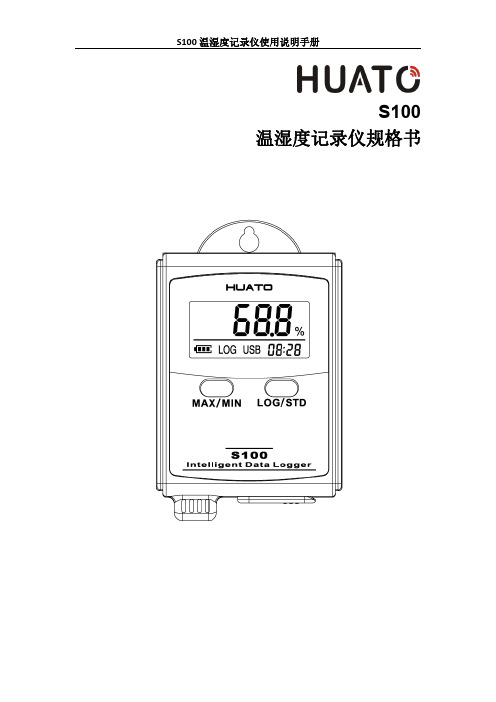
S100温湿度记录仪规格书目录第一章产品介绍 (1)1.1介绍 (1)1.2特性 (1)1.3应用环境 (1)1.4记录仪数据 (2)1.5温湿度记录仪S100-ET/S100-EX外观 (2)1.6温湿度记录仪S100-T/S100-TH外观 (3)1.7S100系列温度记录仪显示屏 (3)1.8S100系列温湿度记录仪显示屏 (4)1.9按键功能介绍 (4)1.10设备状态说明 (4)第二章软件使用指南 (7)2.1计算机硬件的要求 (7)2.2USB驱动安装 (7)2.3LogPro软件使用 (9)2.3.1读取和设置记录仪属性 (9)2.3.2参数设置说明 (10)2.3.3查看数据 (10)2.3.4删除数据 (11)3.1液晶屏显示暗淡 (12)3.2日期&时间错误 (12)3.3软件运行错误 (12)第一章产品介绍1.1介绍华图S100系列记录仪是华图公司最新推出的用于疫苗、冷藏运输、低温冷库等场所的具有国内领先水平的温度测量仪器,采用原装进口之温湿度传感器,精度高,一致性非常好,两节1.5V7号电池供电,连续工作时间达6个月以上,是国家技术监督总局认可的计量仪器。
1.2特性(1)外形小巧精致,使用方便;(2)传感器由瑞士生产,精度高;(3)2节1.5V7号电池可以工作6个月以上,25℃环境(采样间隔60秒,记录间隔300秒);(4)主机尺寸:57x92x20mm;(5)LCD屏幕尺寸:37x17mm;(6)温度和湿度外探针直径:16mm;(7)温度外探头直径:6mm;1.3应用环境(1)疫苗(2)冷藏运输(3)低温冷库(4)工作及生活区域(5)超市1.4记录仪数据1.5温湿度记录仪S100-ET/S100-EX外观LCD显示区型号标签LOG/STD:记录和开关机按键电池盖,打开可更换电池MIN/MIN:最大最小值查看按键USB接口外置传感器接口外置温湿度传感器(S100-EX/S100-EX+)挂孔外置温度传感器(S100-ET/S100-ET+)1.6温湿度记录仪S100-T/S100-TH外观LCD显示屏挂孔LOG/STD按键型号标签MAX/MIN按键电池盖传感器USB端口1.7S100系列温度记录仪显示屏温湿度数值显示区域USB连接标志记录过程中的最大值显示年-月日-时分切换显示记录过程中的最小值华氏度单位符号电池电量摄氏度单位符号记录状态标志1.8S100系列温湿度记录仪显示屏温湿度数值显示区域USB连接标志记录过程中的最大值显示年-月日-时分切换显示记录过程中的最小值湿度单位符号电池电量华氏度单位符号记录状态标志摄氏度单位符号1.9按键功能介绍:进行当前值与记录过程中的最大值、最小值切换(数值锁定);:设备关机时,长按5S后开机进入待机模式,再按3S进入记录模式;记录模式下,按3S可进入待机模式(仅进入待机模式),在待机模式下,按5S 关闭设备。
海尔 EHGS100FMATE81U1 10公斤热泵干衣机 使用说明书
洗衣机使用说明书型号EHGS100FMATE81U1• 本说明书为通用手册• 本公司保留说明书解释权• 产品外观请以实物为准• 阅后请与发票一并妥善保存• 如遇产品技术或软件升级,恕不另行通知• 本产品只适合在中国大陆销售和使用1. 产品介绍1 1.1. 部件介绍1 1.1.1. 产品部件1 1.2. 技术参数1 1.2.1. 技术数据11.2.2. 产品尺寸及安装要求12. Wi-Fi连接3 2.1. APP下载3 2.1.1. 下载途径3 2.2. 智慧物联32.2.1. 功能介绍33. 使用说明4 3.1. 安全注意事项4 3.1.1. 标志说明4 3.1.2. 电气要求4 3.1.3. 运输安装要求4 3.1.4. 放置场景要求4 3.1.5. 使用要求4 3.1.6. 烘干衣物要求5 3.1.7. 清洁保养要求5 3.1.8. 儿童、特殊人群注意事项5 3.2. 干衣准备5 3.2.1. 干衣检查5 3.2.2. 干衣注意事项5 3.3. 安装说明6 3.3.1. 调整底脚6 3.3.2. 安装烘干支架6 3.3.3. 外接排水管6 3.3.4. 门换向6 3.4. 干衣操作6 3.4.1. 基本操作6 3.4.2. 操作面板6 3.4.3. 程序指南8 3.4.4. 衣物重量参考9 3.5. 清洁维护9 3.5.1. 清理过滤网9 3.5.2. 清理水盒10 3.5.3. 清洁104. 售后服务11 4.1. 疑问解答11 4.1.1. 故障排除11 4.1.2. 显示代码及处理方法11 4.2. 保修说明11 4.2.1. 干衣机保修说明11 4.3. 有害物质11 4.3.1. 有害物质的名称与含量111. 产品介绍1.1. 部件介绍1.1.1. 产品部件正面说明书中所有图示均为示意图,由于产品改进及系列化扩展,您所得到的产品外观、颜色及功能可能于此图片不一致,请以实际产品为准。
Ocean Signal S100用户手册说明书
User ManualEnglishSearch and RescueTransponderS100© 2022 Ocean Signal LtdThe technical data, information and illustrations contained in this manual were believed to be correct at the time of print. Ocean Signal Ltd reserve the right to change specifications and other information contained in this manual as part of our continual improvement process.No part of this manual may be reproduced, stored in a retrieval system or transmitted in any form, electronic or otherwise, without the prior and express written permission of Ocean Signal Ltd.No liability can be accepted for any inaccuracies or omissions in this manual.Ocean Signal® and safeSEA® are registered trademarks of Ocean Signal Ltd.14/06/2022912S-00678 v01.203IN CASE OF EMERGENCY• REMOVE THE SART FROM ITS MOUNTING OR HOUSING • ACTIVATE THE SART:• TETHER THE SART TO THE LIFE RAFTUSING THE LANYARD TO AVOID IT BEING LOST OVERBOARD.FOR MAXIMUM EFFECTIVENESS, THE SART NEEDS TO BE MOUNTED AT LEAST 1 METER ABOVE THE SEA.• THE SART MAY BE ATTACHED TO THEROOF OF THE LIFE RAFT USING THE TIE PROVIDED IN THE LIFE RAFT. ALTERNATIVELY THE SART MAY BE MOUNTED ON THE TELESCOPIC POLE SUPPLIED AND ATTACHED TO THE SIDE OF THE LIFE RAFT.NOTE: Refer to section 4.3 for deactivation instructions 1. Break off the protective cover2. Slide and hold the Green switch to the left,then slide the Red switch into the down position and release the Green switch4 912S-00678 v01.2014/06/2022CONTENTS1. GENERAL51.1 Exposure to RF Electromagnetic Energy 51.2 Warnings 52.S100 OVERVIEW63. INSTALLATION 74. O P ERATION84.1 Deploy m ent 84.2 Activation 94.3 Deactivation 104.4 Testing 105. BATTERIES115.1 Battery Replacement126. A P P ENDIX 136.1 Maintenance and Troubleshooting 136.2 Accessories 136.3 Specifications 136.4 Approvals 146.5 Limited Warranty1414/06/2022 912S-00678 v01.20 51.GENERAL1.1 Exposure to RF Electromagnetic EnergyThis product has been evaluated for compliance with the FCC RF exposure limits given in CFR 47 part 2.1093 at a distance of 2.5cm for “Occupational Use Only”1.2 Warnings!Always operate the SART with any part of the device at least 6cm (2.4in) away from your body.!The SafeSEA S100 SART is designed for use in emergency only. Only operate it in situations of grave and imminent danger.!The SafeSEA S100 SART incorporates a protective tab over the operating controls to avoid accidental activation and indicate that the unit has been used.!After any period of operation, the battery should be replaced and the unit returned to your local service dealer for replacement of the protective tab. !Always replace the battery before the expiry date is exceeded to ensure full operating capacity in case of emergency.!Please ensure you follow local regulations before disposing of this item. Ensure the battery is removed from the unit before disposal.6 912S-00678 v01.2014/06/20222.S100 OVERVIEW1. Telescopic Mounting Pole2. Lanyard Attachment Point3. Test Switch4. Indicator LED5. Pole Attachment Point6. Interlock Switch7. Activation Switch8. Tear off tag9. Battery compartment in base14/06/2022 912S-00678 v01.20 73.INSTALLATIONThe S100 is supplied with a quick release mounting bracket. This bracket should bemounted on a suitable wall or bulkhead in a position where it can easily be retrieved in an emergency.Although the S100 is rugged and waterproof, Ocean Signal recommends mounting the SART in a protected position whenever possible.!Do not mount the SART closer than 1 meter to any steering compass as this may affect the accuracy of the compass.!Keep the S100 away from any strong magnetic sources such as loudspeak-ers, compass compensation magnets, etc.Mark the location of the four screw holes onto the mounting position. Pre-drill the holes if required then screw the mounting bracket to the surface using the four No6 x 5/8” screws supplied.The SART simply clips onto the mounting bracket.84.OPERATION4.1 Deploymentof 1 meter above sea level.er.!lost overboard.on them.14/06/2022912S-00678 v01.209Raise the SART vertically and attach the pole to the life raft. Most life rafts are fitted with suitable attachments to accommodate the SART pole.Alternatively, the SART may be attached directly to the life raft canopy.4.2 Activation!The SART should only be activated if there is grave and imminent danger to the vessel and its crew.To activate the SART, remove the unit from its mounting bracket.Break off the clear protective cover over the Green and Red switches.Holding the Green switch to the left, push the Red switch down and hold.While holding the Red switch down, release the Green switch to lock the Red switch in the active position.During operation, the Red LED next to the Test switch will flash once every 2-3 seconds to indi-cate the SART is operational:When activated by a received radar pulse the Red LED will start flashing rapidly:10912S-00678 v01.2014/06/20224.3 DeactivationIf the SART has been inadvertently activated, it can be turned off simply by reversing the activation process.Slide the Green switch to the left - the Red switch will return to the off position.Release the Green switch.It is not possible for the user to replace the clear protective cover . Return the SART to an Ocean Sig-nal authorised service centre for replacement.4.4 TestingIt is recommended that the S100 SART is tested periodically. A full test should be carried out in conjunction with an X-band radar on a nearby vessel if possible. A full test should always becarried out as part of the annual service, with short inspections every two months.Activate Test Mode by rotating the grey test switch clockwise and holding.If there is radar activity in the area then the Red LED will start to flash intermittently, indicating that the radar signals are being received.The radar display of any vessels within radar de-tection range of your location will now be showing the return from the SART.Depending on the distance of the vessel to the SART and the tuning of the radar , the display will vary between a set of concentric rings to a line of twelve blips in a straight line on a bearing between the vessel and the SART.!Test Mode is the same as Activation Mode, so keep the test duration to a minimum to avoid falsely alerting other vessels that you may be indistress and minimise battery drain.14/06/2022 912S-00678 v01.20 115. BATTERIESThe S100 SART uses a Lithium Iron Disulfide battery pack to power the device. These bat-teries have a five year storage life before any significant reduction in capacity. Each battery is marked with an expiry date, which is located at the base of the unit.! The battery should be replaced before the expiry date has passed to ensure reliable operation and full capacity in emergency situations.! Always use batteries manufactured by Ocean Signal. Failure to do so will in-validate the type approval and may mean the unit does not operate correctly in a distress situation.! Never dispose of batteries in a fire.! Never puncture or attempt to dismantle the battery.! Never attempt to charge the battery.! Extreme temperature caused by failure to observe the above warnings may cause the battery to explode or catch fire, which may result in injury or damage to surrounding personnel or property.!Dispose of used batteries in a responsible manner. National or local reg-ulations on battery disposal may apply including restricting the disposal of batteries in domestic refuse. For the Product Safety Data Sheet and advice on battery transportation, please see the Ocean Signal web site at .12 912S-00678 v01.2014/06/20225.1 Battery ReplacementThe battery may be changed by the user , although commercial vessels may be subject to local regulations relating to Shore Based Maintenance that prevent this.Remove the SART from its mounting bracket and turn it over .screw.Undo the screw using the 3mm Allen (Hex) key provided.Remove the pack from the main body.Insert new battery pack, ensuring that the rub-ber seal is correctly in position and the pack is pushed home fully. Tighten screw.Ensure that any maintenance records on-boardare updated with the new battery expiry date.14/06/2022 912S-00678 v01.20 136. APPENDIX6.1 Maintenance and TroubleshootingThe S100 SART should not need servicing during its lifetime, with the exception of changing the battery before the marked expiry date.Regular cleaning, inspection and testing are advised - clean any grime or salt residue off the unit with a weak solution of detergent in warm water . Never use solvents as this may affect the structural integrity of the plastics used. Rinse well with fresh water after clean-ing.Inspect the unit for signs of case damage or cracks, check the labels are intact and the battery is within the expiry date. Make sure the telescopic pole (if provided) is still present and is free to extend.Check for correct SART operation using the Test Mode (see section 4.4). If the unit appears to fail testing, check the following points before contacting a service representative:! Are there any vessels in the vicinity that would have an active radar system to trigger the SART?!Is the SART being shielded from being radar visible to other vessels? 6.2 AccessoriesReplacement Lithium Battery for S100 LB3S Ocean Signal Part Number 711S-0060914 912S-00678 v01.2014/06/20226.3 SpecificationsTransmitter Frequency 9.2-9.5GHz Output Power (EIRP) >400mW Number of sweeps/per interrogation 12Supply Battery Lithium Iron Disulfide (LiFeS2)Operating life (standby/active)96/12 hours at -20°CTest Standards IEC61097-2, IEC60945,Environmental IEC60945 Category Portable Temperature Range (operating) -20°C to +55°C Temperature Range (storage) -30°C to +65°C Waterproof 10 meters Drop proof (on water) 20 meters Compass safe distance 1 meter 6.4 ApprovalsThe SafeSEA S100 SART is approved under the EU Marine Equipment Directive under MED/4.18 of the current implementing regulation. The Declaration of Conformity can be downloaded from: /products/S100The SafeSEA S100 SART is approved in the UK under MSN 1874 (Amendment 5 M+F))The SafeSEA S100 SART complies with the GMDSS provisions of part 80 of the FCC rules.14/06/2022 912S-00678 v01.20 156.5 Limited WarrantyYour SafeSEA S100 SART is warranted against manufacturing defects in materials and workmanship for a period of two years from date of purchase. Ocean Signal Ltd will, at its discretion, repair or replace a faulty product free of charge, including return carriage costs to the owner.For further assistance, please contact our Technical Service Department: Email:********************Accidental damage and misuse or non-approved modifications are not covered by this war-ranty. This warranty does not affect your statutory rights.Dealer Stamp:Date of Purchase:Ocean Signal Ltd. Unit 4, Ocivan Way MargateCT9 4NNUnited Kingdom******************** 。
S100A 单轴控制器说明书(全)
ENC-S100A 单轴控制系统使用手册V3.4南京华兴电机制造有限公司南京希曼得自动化设备有限公司2009-12目录1 简介 (4)2规格说明 (4)2.1 S100A 主要性能参数 (4)2.2 S100A 电器规格 (5)2.3 环境温度 (5)3 操作说明 (5)3.1操作面板说明 (5)3.1.1 CNC 面板见图2-1 (5)3.1.2键盘说明 (6)3.1.3坐标显示 (6)3.2【自动】操作模式 (6)3.2.1 自动执行 (6)3.2.2 等待IX (7)3.2.3 丢标IX (8)3.3【手动】操作模式 (8)3.4【参数】操作模式 (9)3.4.1 参数默认值 (9)3.4.2 参数保存 (9)3.4.3 参数查询及修改 (9)3.4.4 参数列表 (9)4编程说明 (9)4.0 进入编程界面 (9)4.1 功能语句一览表 (9)4.2 功能语句详细说明 (11)4.2.1 电机运行 (11)4.2.2本句无效 (12)4.2.3 程序循环 (13)4.2.4 坐标设定 (13)4.2.5 延时设定 (14)4.2.6 持续运行 (15)4.2.7 输出信号 (16)5安装、接线及调试 (17)5.1 安装与配线注意事项 (17)5.2 安装方向与空间 (17)5.3 安装环境 (18)5.4 前面板尺寸 (18)5.5 后面板布局 (19)5.6 输出信号接口定义..... .. (20)1简介ENC-S100A 型单轴控制器,是一款经济型单轴控制系统,可以控制一台数字式交流伺服电机或一台步进电机。
本系统采用蓝色背光的LCD液晶显示屏,中文操作界面。
在编程方面,本机摈弃了繁琐的传统G/M代码编程方式,采取用户自选功能语句的方式,编写控制程序,大大降低了传统数控系统对操作人员的技能要求,使得ENC-S100A适于在更为广阔的自动化领域得到推广应用。
为了您的正确使用和安全,请先仔细阅读本手册。
DIgITech-DOD-S100数字效果器中文说明书
DIgITech-DOD-S100数字效果器中文说明书S—100的使用手册前板1.配置矩阵:这个距阵展示在s—100中可利用的五个不同的效果配置2.输入表/效果显示:在节目中这个仪表显示进入该单元的输入信号。
在编辑中,它显示正在使用的效果。
3.数字显示器:在节目方式中,这个数字显示器将显示节目编号(小数点表示用户节目)。
在编辑方式中,该显示器将指示这些效果及参数值。
4.节目/数据轮盘:在节目方式中,这个轮盘用于改变节目的当前使用单元,在编辑方式中,被用于选择效果及改变参数。
5.节目按钮(program):使S100返回到按过时的节目方式。
6.存储按钮(store):用于S100中存储节目修改。
7.配置按钮(config):用于选择配置方式。
一旦按过之后,使用节目/数据轮盘以选择节目的不同效果配置。
8.混频/MIDI(mix/midi):该按钮用于旋转演习信号ON(接通)OFF(断开)及选择MIDI 通道,由此收到节目改变信息。
9.,a----g节目编辑按钮::这七个按钮用于对S100进行按键编辑修改,功能如下: 9---a均衡器/控制电路(EQ/Gate)-----这个按钮(连同四个参数按钮)是用于调整三个频带均衡器及噪声门限和释放,按一次选择均衡器,按两次选择噪声控制电路. 9---b驱动A(Engine A)----这个按钮选择驱动器A效果模块。
当按下该按钮,可使用轮盘改变这个模块中使用的效果。
9---c驱动B(Engine B)----这个按钮选择驱动器B效果模块。
当按下该按钮,可使用轮盘改变这个模块中使用的效果。
9---d参数1(param1)/预置延迟(predelay):该按钮选择参数1,用于编辑连同轮盘一起使用。
同样也是混响效果的预置延迟参数。
9---e参数2(param2)/混响衰减(decay):该按钮选择参数2,用于编辑连同轮盘一起使用。
同样也是混响效果的混响衰减参数。
9---f参数3(param3)/阻尼(damping):该按钮选择参数3,用于编辑连同轮盘一起使用。
- 1、下载文档前请自行甄别文档内容的完整性,平台不提供额外的编辑、内容补充、找答案等附加服务。
- 2、"仅部分预览"的文档,不可在线预览部分如存在完整性等问题,可反馈申请退款(可完整预览的文档不适用该条件!)。
- 3、如文档侵犯您的权益,请联系客服反馈,我们会尽快为您处理(人工客服工作时间:9:00-18:30)。
DIgITech-DOD-S100数字效果器中文说明书S—100的使用手册前板1.配置矩阵:这个距阵展示在s—100中可利用的五个不同的效果配置2.输入表/效果显示:在节目中这个仪表显示进入该单元的输入信号。
在编辑中,它显示正在使用的效果。
3.数字显示器:在节目方式中,这个数字显示器将显示节目编号(小数点表示用户节目)。
在编辑方式中,该显示器将指示这些效果及参数值。
4.节目/数据轮盘:在节目方式中,这个轮盘用于改变节目的当前使用单元,在编辑方式中,被用于选择效果及改变参数。
5.节目按钮(program):使S100返回到按过时的节目方式。
6.存储按钮(store):用于S100中存储节目修改。
7.配置按钮(config):用于选择配置方式。
一旦按过之后,使用节目/数据轮盘以选择节目的不同效果配置。
8.混频/MIDI(mix/midi):该按钮用于旋转演习信号ON(接通)OFF(断开)及选择MIDI 通道,由此收到节目改变信息。
9.,a----g节目编辑按钮::这七个按钮用于对S100进行按键编辑修改,功能如下: 9---a 均衡器/控制电路(EQ/Gate)-----这个按钮(连同四个参数按钮)是用于调整三个频带均衡器及噪声门限和释放,按一次选择均衡器,按两次选择噪声控制电路. 9---b驱动A(Engine A)----这个按钮选择驱动器A效果模块。
当按下该按钮,可使用轮盘改变这个模块中使用的效果。
9---c驱动B(Engine B)----这个按钮选择驱动器B效果模块。
当按下该按钮,可使用轮盘改变这个模块中使用的效果。
9---d参数1(param1)/预置延迟(predelay):该按钮选择参数1,用于编辑连同轮盘一起使用。
同样也是混响效果的预置延迟参数。
9---e参数2(param2)/混响衰减(decay):该按钮选择参数2,用于编辑连同轮盘一起使用。
同样也是混响效果的混响衰减参数。
9---f参数3(param3)/阻尼(damping):该按钮选择参数3,用于编辑连同轮盘一起使用。
同样也是混响效果的阻尼参数。
9---g参数4(param4)/电平(level):该按钮选择参数3,用于编辑连同轮盘一起使用。
10旁路(bypass):该按钮用于使S100的全部数字效应旁路,及让原来的演习信号通过。
后板1 输入电平:这个按钮控制进入S100的信号电平。
作为最佳性能,设置这个电平,输入电平指示器位于前板。
2 左/单输入:用于左声道或单声道输入。
当使用左声道输入插座时,该信号是发送到左声道及右声道两侧输入(即为单声道)。
3 右输入:用于S100右声道输入插座。
与左声道一起使用将保持立体声效果。
4 左/单输出:S100的左声道音频输出。
如果希望是单声道效果,必须使用左声道输出。
5 右输出:S100的右声道输出。
与左声道一起使用具有立体声效果。
6 交流电输入:交流连接插座。
7 脚塌开关插座:用于数字技术FS300脚塌开关的接入,控制节目的变化及使用S100的数字效果旁路。
8 MIDI插入:这个MIDI(电子乐器数字化接口)插座用于接收MIDI节目变化及CC(控制)信息。
操作与编辑节目方式:在S100的节目方式中,你可以使用轮盘,从一个节目到另一个节目。
使用数字FS-300脚踏开关或MIDI节目改变指令,从另一个装置诸如定序器或键盘。
当S100在节目方式中,你希望退出或返回节目方式时,只需按<节目>按钮。
存储变化:当一个节目以被修改,当这个单元在节目方式中,节目数字将在数字显示器中闪烁。
为了存储变化,按一次〈存储〉按钮。
显示器交替5T和使用节目位置将被存储。
简单而言,S100给你选择存储修改节目数字1—99,这点你可以使用〈节目/数字〉轮盘改变存储到另一个节目数字。
当预设目标位置正确时,再按一次〈存储〉按钮。
显示器回立刻读出存储号码。
显示修改节目以被存储。
选择效果配置S100为您提供五种不同的效果配置供选择:五种配置在前面板显示如下:Engine Configuration 驱动配置效果模块尺寸效果配置1使用一种效果模块,因为两种程序驱动连在一起,较大的模块允许你延迟更长时间,有更多的音响混响,效果配置2---5使用Half(一半)尺寸效果模块使你每个节目有两种效果。
选择任何一种效果配置,只须简单操作如下:按〈配置〉按钮显示将读出:CF 显示你在配置选择方式中,而后显示如下:C1 旋转〈节目/数字〉转轮直到您所须的效果配置在显示其中显示,C1—5,若退出效果配置菜单,只须按〈节目〉按钮显示器将显示节目数字,直到节目变化被储存或你改变到下一个节目。
调整演习路径混频这个编辑程序允许你打开演习信号路径OFF(断开),以使用控制台的效果发送或ON(接通)以输入单个乐器信号(诸如吉他等)程序如下:在S100的效果配置中编辑演习信号路径(旋转ON或OFF),按下〈混频/MIDI〉按钮显示器将读出:dr 显示演习路径混频,然后读出ON,显示演习信号接通。
若你希望切断演习路径,简单的按顺时针方向旋转〈节目/数据〉轮盘,显示器将读出OFF。
此时显示演习信号路径断开,S100为环绕信号,若退出这个方式,按〈节目〉按钮。
注意:若在一个节目中使用震音、重音、合成、混想等效果时,演习路径将自动断开,因为演习信号已包括这些效果。
选择MIDI通道及MIDI CC信息选择MIDI通道,其中S100接收节目变化信息,从节目方式,按下〈混频/MIDI〉按钮两次,显示器将简短读出:CH(表示MIDI通道方式),如下: 1 现转动〈节目/数据〉转轮,以选择所希望的MIDI通道。
作为MIDI通道的选择,选择范围1---16,ON及OFF。
MIDI 节目变化数目将是如下:1---99 = 节目100 = 效果旁路101 = 退出效果旁路102 = 效果旁路触发器103 = 选择用户节目库104 = 选择工厂节目库按〈节目〉按钮以退出MIDI通道菜单。
MIDI CC (控制台)信息S100将同样接收MIDI 信息用于下述参数控制:演习电平是由MIDI控制台数字CC7来转动ON接通、OFF断开。
均衡器及噪声控制电路调整这个编辑功能对按键均衡器及噪声控制电路进行修改,以定制改变你的声音用于每个节目。
过程如下:1 均衡器调整S100提供一个三频段均衡器,低频均衡器、参数频率、参数电平、高频均衡器参数。
可以对这四个参数进行调整,具体操作如下:按下〈均衡器/控制电路〉按钮一次,显示器读出: E 这时对四个不同的均衡器参数进行调整,使用〈参数1—4〉按钮。
有关各个参数及值范围列表如下:参数1-------LoEQ---低频均衡器的范围-12到+12Db 参数2-------参数频率—有关参数的频率范围从1到2b 参数3-------参数电平—有关参数电平的范围从-12db到+12db 参数4-------HiEQ---高频均衡器的范围从-12dB 到+12dB 修改之后,按下各自的〈参数〉按钮,然后转动〈节目/数据〉轮盘。
当修改之后,保存修改参数,按下〈节目〉按钮返回到节目方式。
调整噪声控制电路: S100使你能够定制的改变噪声控制电路的能力(门限及释放),用于每个节目,使用步骤如下:按两次<均衡器/控制电路>按钮,显示器将显示: Ng 表示你在噪声控制电路编辑方式中: 这时按下<参数1>按钮几th将出现,提示你用用转动<节目/数据>轮盘来调整噪声控制电路门限(阈值),有关噪声控制电路门限(阈值)是从99—0,OFF(断开). 为调整噪声控制电路释放,按下<参数2>按钮显示器将读出: TE 提示你使用<节目/数据>轮盘,调整噪声控制电路释放参数.范围1---99. 调整之后进行存储,按<节目>按钮,以返回节目方式. 编辑驱动A和B模块 S100给你两种驱动模块,完全程序化.下列部分将解释驱动A和B的简单编辑程序: 选择和编辑效果从节目方式,按下<驱动A>或<驱动B>按钮,正在使用的效果模块将使效果器显示器中下列二极管发亮. 注意:为编辑驱动B,配置2—5必须使用. 现在旋转<节目/数据>轮盘以选择将使用的效果.效果显示发光二极管及数字显示器将在新的效果模块选定后变化. 一旦选定所需使用的效果,你可以使用<参数1—4>编辑按钮从修改所选的效果参数. 若在选定节目的所有编辑程序完成之后,一定要存储任何变化并按<节目>岸钮返回节目方式..双效果处理器,立体声输入输出,96DB信噪比,5条效果处理结构,20比特A/D和D/A转换。
使用简介;面板说明;1。
PROGRAM;程序选择/呼出2。
STORE;储存3。
CONFIG;结构4。
MIX/MIDI;混合/MIDI5。
EQ/GATE;均衡/闸门6。
ENGINE A B ;AB混响器7。
PARAM1-4参数1-48。
BYPASS;旁通1。
先按下PROGRAM 程序键,用旋钮选择一个程序,S100共有99个预置程序这99个程序可以修改,并储存到应用程序库里,使用[应用程序]时,USER灯会亮起。
2。
按下CONFIG结构键,再选择二个处理器之间的结构,C1-C5。
面板上有示意图。
3。
按ENGINE A 键 A混响器选择处理器的效果类型。
4。
选定处理器的效果类型后,再选择PARAM参数1-4键,细调节其效果参数,[如选结构C2,C3,C4,C5,需再调ENGINE B键B混响的效果及参数。
5。
当调好所需要的效果后,按下STOER储存键,将资料储存到USER 应用程序里。
S-100技术参数;频率响应;20-20KHZ +/-0。
5DB信噪比;A计权记忆容量;100个用户程序,100个应用程序,取样频率;46。
875KHZ。
输入/输出;大二芯插头百灵达DSP1100P反馈抑制器是德国Behringer公司在原来的DSP1100反馈抑制器的基础上改进后生产的,它在保持了原反馈抑制器的功能与特点的基础上,为了提高抗干扰能力,将原来的非平衡连接改成平衡连接,在调整方法上与DSP1100没有任何区别。
功能键介绍(1)FILTER SELECT滤波器选择。
共有12个滤波器,可以抑制12个频点啸叫。
(2)FILTER MODE滤波方式。
有OF(关闭)、PA(参量均衡)、AU(自动)和SI(单点)等4种滤波方式。
(3)ENGINE左声道工作,指示灯不亮时,左声道处于旁路状态。
(4)ENGINE R右声道工作,指示灯不亮时,右声道处于旁路状态。
同时按(3)(4),两个指示灯同时亮,此时左右声道都运行,一般采用这种形式。
(5)FREQUENCY频率。