泰克MDO3000系列示波器存储数据具体操作培训讲学
泰克示波器培训交流综述
很多串行测试规范规定了示波器采集数据信号的最小存储深度。例如PCIE 2.0的规范要求捕获1Mllion UI的Bit,需要的存储深度至少为8M。
HDMI 1.4 需要至少16M的存储深度进行分析。
抖 动 幅 度
Tektronix
11
带宽 & 谐波
Digital Square Wave – Odd Fourier Sums
1
Fundamental (1st Harmonic) 3rd Harmonic 5th Harmonic Fourier Square Wave (1st-5thH)
0
-1 0
12
50
100
示波器带宽对测量波形影响
45
有源差分探头
PROBE HEAD + _
Scope Ch 1 Amplifier
SCOPE
VOUT
Typical CMRR 10,000 : 1 @ DC 2000 : 1 @ 20 MHz
Advantages:
Disadvantages:
Lower Input Capacitance Higher CMRR vs Frequency Than Passive Differential Pair Compatible With 50 and 1 M Single-ended Systems
0 dB 6 div at 50 kHz
- 3 dB 4.2 div at bandwidth
8
上升/下降时间 vs. 示波器带宽
上升时间(示波器) ~= 0.35/带宽(示波器)
Tektronix MDO3000 Series 数字多功能作业仪用户指南说明书
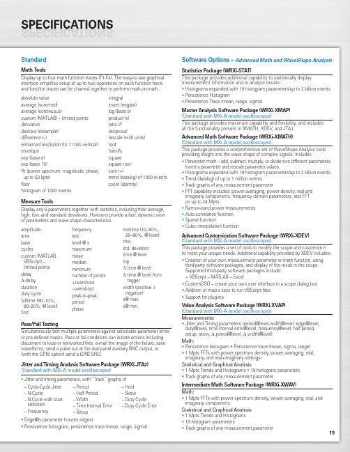
19StandardMath ToolsDisplay up to four math function traces (F1-F4). The easy-to-use graphical interface simplifies setup of up to two operations on each function trace;and function traces can be chained together to perform math-on-math.absolute value integralaverage (summed)invert (negate)average (continuous)log (base e)custom (MATLAB) – limited points product (x)derivativeratio (/)deskew (resample)reciprocaldifference (–)rescale (with units)enhanced resolution (to 11 bits vertical)roof envelope (sinx)/x exp (base e)square exp (base 10)square root fft (power spectrum, magnitude, phase,sum (+)up to 50 kpts) trend (datalog) of 1000 events floorzoom (identity)histogram of 1000 eventsMeasure ToolsDisplay any 6 parameters together with statistics, including their average,high, low, and standard deviations. Histicons provide a fast, dynamic view of parameters and wave-shape characteristics.Pass/Fail TestingSimultaneously test multiple parameters against selectable parameter limits or pre-defined masks. Pass or fail conditions can initiate actions including document to local or networked files, e-mail the image of the failure, save waveforms, send a pulse out at the rear panel auxiliary BNC output, or (with the GPIB option) send a GPIB SRQ.Jitter and Timing Analysis Software Package (WRXi-JTA2)(Standard with MXi-A model oscilloscopes)•Jitter and timing parameters, with “Track”graphs of •Edge@lv parameter (counts edges)• Persistence histogram, persistence trace (mean, range, sigma)Software Options –Advanced Math and WaveShape AnalysisStatistics Package (WRXi-STAT)This package provides additional capability to statistically display measurement information and to analyze results:• Histograms expanded with 19 histogram parameters/up to 2 billion events.• Persistence Histogram• Persistence Trace (mean, range, sigma)Master Analysis Software Package (WRXi-XMAP)(Standard with MXi-A model oscilloscopes)This package provides maximum capability and flexibility, and includes all the functionality present in XMATH, XDEV, and JTA2.Advanced Math Software Package (WRXi-XMATH)(Standard with MXi-A model oscilloscopes)This package provides a comprehensive set of WaveShape Analysis tools providing insight into the wave shape of complex signals. Includes:•Parameter math – add, subtract, multiply, or divide two different parameters.Invert a parameter and rescale parameter values.•Histograms expanded with 19 histogram parameters/up to 2 billion events.•Trend (datalog) of up to 1 million events•Track graphs of any measurement parameter•FFT capability includes: power averaging, power density, real and imaginary components, frequency domain parameters, and FFT on up to 24 Mpts.•Narrow-band power measurements •Auto-correlation function •Sparse function• Cubic interpolation functionAdvanced Customization Software Package (WRXi-XDEV)(Standard with MXi-A model oscilloscopes)This package provides a set of tools to modify the scope and customize it to meet your unique needs. Additional capability provided by XDEV includes:•Creation of your own measurement parameter or math function, using third-party software packages, and display of the result in the scope. Supported third-party software packages include:– VBScript – MATLAB – Excel•CustomDSO – create your own user interface in a scope dialog box.• Addition of macro keys to run VBScript files •Support for plug-insValue Analysis Software Package (WRXi-XVAP)(Standard with MXi-A model oscilloscopes)Measurements:•Jitter and Timing parameters (period@level,width@level, edge@level,duty@level, time interval error@level, frequency@level, half period, setup, skew, Δ period@level, Δ width@level).Math:•Persistence histogram •Persistence trace (mean, sigma, range)•1 Mpts FFTs with power spectrum density, power averaging, real, imaginary, and real+imaginary settings)Statistical and Graphical Analysis•1 Mpts Trends and Histograms •19 histogram parameters •Track graphs of any measurement parameterIntermediate Math Software Package (WRXi-XWAV)Math:•1 Mpts FFTs with power spectrum density, power averaging, real, and imaginary componentsStatistical and Graphical Analysis •1 Mpts Trends and Histograms •19 histogram parameters•Track graphs of any measurement parameteramplitude area base cyclescustom (MATLAB,VBScript) –limited points delay Δdelay duration duty cyclefalltime (90–10%, 80–20%, @ level)firstfrequency lastlevel @ x maximum mean median minimumnumber of points +overshoot –overshoot peak-to-peak period phaserisetime (10–90%, 20–80%, @ level)rmsstd. deviation time @ level topΔ time @ levelΔ time @ level from triggerwidth (positive + negative)x@ max.x@ min.– Cycle-Cycle Jitter – N-Cycle– N-Cycle with start selection – Frequency– Period – Half Period – Width– Time Interval Error – Setup– Hold – Skew– Duty Cycle– Duty Cycle Error20WaveRunner WaveRunner WaveRunner WaveRunner WaveRunner 44Xi-A64Xi-A62Xi-A104Xi-A204Xi-AVertical System44MXi-A64MXi-A104MXi-A204MXi-ANominal Analog Bandwidth 400 MHz600 MHz600 MHz 1 GHz 2 GHz@ 50 Ω, 10 mV–1 V/divRise Time (Typical)875 ps500 ps500 ps300 ps180 psInput Channels44244Bandwidth Limiters20 MHz; 200 MHzInput Impedance 1 MΩ||16 pF or 50 Ω 1 MΩ||20 pF or 50 ΩInput Coupling50 Ω: DC, 1 MΩ: AC, DC, GNDMaximum Input Voltage50 Ω: 5 V rms, 1 MΩ: 400 V max.50 Ω: 5 V rms, 1 MΩ: 250 V max.(DC + Peak AC ≤ 5 kHz)(DC + Peak AC ≤ 10 kHz)Vertical Resolution8 bits; up to 11 with enhanced resolution (ERES)Sensitivity50 Ω: 2 mV/div–1 V/div fully variable; 1 MΩ: 2 mV–10 V/div fully variableDC Gain Accuracy±1.0% of full scale (typical); ±1.5% of full scale, ≥ 10 mV/div (warranted)Offset Range50 Ω: ±1 V @ 2–98 mV/div, ±10 V @ 100 mV/div–1 V/div; 50Ω:±400mV@2–4.95mV/div,±1V@5–99mv/div,1 M Ω: ±1 V @ 2–98 mV/div, ±10 V @ 100 mV/div–1 V/div,±10 V @ 100 mV–1 V/div±**********/div–10V/div 1 M Ω: ±400 mV @ 2–4.95 mV/div, ±1 V @5–99 mV/div, ±10 V @ 100 mV–1 V/div,±*********–10V/divInput Connector ProBus/BNCTimebase SystemTimebases Internal timebase common to all input channels; an external clock may be applied at the auxiliary inputTime/Division Range Real time: 200 ps/div–10 s/div, RIS mode: 200 ps/div to 10 ns/div, Roll mode: up to 1,000 s/divClock Accuracy≤ 5 ppm @ 25 °C (typical) (≤ 10 ppm @ 5–40 °C)Sample Rate and Delay Time Accuracy Equal to Clock AccuracyChannel to Channel Deskew Range±9 x time/div setting, 100 ms max., each channelExternal Sample Clock DC to 600 MHz; (DC to 1 GHz for 104Xi-A/104MXi-A and 204Xi-A/204MXi-A) 50 Ω, (limited BW in 1 MΩ),BNC input, limited to 2 Ch operation (1 Ch in 62Xi-A), (minimum rise time and amplitude requirements applyat low frequencies)Roll Mode User selectable at ≥ 500 ms/div and ≤100 kS/s44Xi-A64Xi-A62Xi-A104Xi-A204Xi-A Acquisition System44MXi-A64MXi-A104MXi-A204MXi-ASingle-Shot Sample Rate/Ch 5 GS/sInterleaved Sample Rate (2 Ch) 5 GS/s10 GS/s10 GS/s10 GS/s10 GS/sRandom Interleaved Sampling (RIS)200 GS/sRIS Mode User selectable from 200 ps/div to 10 ns/div User selectable from 100 ps/div to 10 ns/div Trigger Rate (Maximum) 1,250,000 waveforms/secondSequence Time Stamp Resolution 1 nsMinimum Time Between 800 nsSequential SegmentsAcquisition Memory Options Max. Acquisition Points (4 Ch/2 Ch, 2 Ch/1 Ch in 62Xi-A)Segments (Sequence Mode)Standard12.5M/25M10,00044Xi-A64Xi-A62Xi-A104Xi-A204Xi-A Acquisition Processing44MXi-A64MXi-A104MXi-A204MXi-ATime Resolution (min, Single-shot)200 ps (5 GS/s)100 ps (10 GS/s)100 ps (10 GS/s)100 ps (10 GS/s)100 ps (10 GS/s) Averaging Summed and continuous averaging to 1 million sweepsERES From 8.5 to 11 bits vertical resolutionEnvelope (Extrema)Envelope, floor, or roof for up to 1 million sweepsInterpolation Linear or (Sinx)/xTrigger SystemTrigger Modes Normal, Auto, Single, StopSources Any input channel, External, Ext/10, or Line; slope and level unique to each source, except LineTrigger Coupling DC, AC (typically 7.5 Hz), HF Reject, LF RejectPre-trigger Delay 0–100% of memory size (adjustable in 1% increments, or 100 ns)Post-trigger Delay Up to 10,000 divisions in real time mode, limited at slower time/div settings in roll modeHold-off 1 ns to 20 s or 1 to 1,000,000,000 events21WaveRunner WaveRunner WaveRunner WaveRunner WaveRunner 44Xi-A 64Xi-A 62Xi-A104Xi-A 204Xi-A Trigger System (cont’d)44MXi-A64MXi-A104MXi-A204MXi-AInternal Trigger Level Range ±4.1 div from center (typical)Trigger and Interpolator Jitter≤ 3 ps rms (typical)Trigger Sensitivity with Edge Trigger 2 div @ < 400 MHz 2 div @ < 600 MHz 2 div @ < 600 MHz 2 div @ < 1 GHz 2 div @ < 2 GHz (Ch 1–4 + external, DC, AC, and 1 div @ < 200 MHz 1 div @ < 200 MHz 1 div @ < 200 MHz 1 div @ < 200 MHz 1 div @ < 200 MHz LFrej coupling)Max. Trigger Frequency with400 MHz 600 MHz 600 MHz 1 GHz2 GHzSMART Trigger™ (Ch 1–4 + external)@ ≥ 10 mV@ ≥ 10 mV@ ≥ 10 mV@ ≥ 10 mV@ ≥ 10 mVExternal Trigger RangeEXT/10 ±4 V; EXT ±400 mVBasic TriggersEdgeTriggers when signal meets slope (positive, negative, either, or Window) and level conditionTV-Composite VideoT riggers NTSC or PAL with selectable line and field; HDTV (720p, 1080i, 1080p) with selectable frame rate (50 or 60 Hz)and Line; or CUSTOM with selectable Fields (1–8), Lines (up to 2000), Frame Rates (25, 30, 50, or 60 Hz), Interlacing (1:1, 2:1, 4:1, 8:1), or Synch Pulse Slope (Positive or Negative)SMART TriggersState or Edge Qualified Triggers on any input source only if a defined state or edge occurred on another input source.Delay between sources is selectable by time or eventsQualified First In Sequence acquisition mode, triggers repeatedly on event B only if a defined pattern, state, or edge (event A) is satisfied in the first segment of the acquisition. Delay between sources is selectable by time or events Dropout Triggers if signal drops out for longer than selected time between 1 ns and 20 s.PatternLogic combination (AND, NAND, OR, NOR) of 5 inputs (4 channels and external trigger input – 2 Ch+EXT on WaveRunner 62Xi-A). Each source can be high, low, or don’t care. The High and Low level can be selected independently. Triggers at start or end of the patternSMART Triggers with Exclusion TechnologyGlitch and Pulse Width Triggers on positive or negative glitches with widths selectable from 500 ps to 20 s or on intermittent faults (subject to bandwidth limit of oscilloscope)Signal or Pattern IntervalTriggers on intervals selectable between 1 ns and 20 sTimeout (State/Edge Qualified)Triggers on any source if a given state (or transition edge) has occurred on another source.Delay between sources is 1 ns to 20 s, or 1 to 99,999,999 eventsRuntTrigger on positive or negative runts defined by two voltage limits and two time limits. Select between 1 ns and 20 sSlew RateTrigger on edge rates. Select limits for dV, dt, and slope. Select edge limits between 1 ns and 20 s Exclusion TriggeringTrigger on intermittent faults by specifying the normal width or periodLeCroy WaveStream Fast Viewing ModeIntensity256 Intensity Levels, 1–100% adjustable via front panel control Number of Channels up to 4 simultaneouslyMax Sampling Rate5 GS/s (10 GS/s for WR 62Xi-A, 64Xi-A/64MXi-A,104Xi-A/104MXi-A, 204Xi-A/204MXi-A in interleaved mode)Waveforms/second (continuous)Up to 20,000 waveforms/secondOperationFront panel toggle between normal real-time mode and LeCroy WaveStream Fast Viewing modeAutomatic SetupAuto SetupAutomatically sets timebase, trigger, and sensitivity to display a wide range of repetitive signalsVertical Find ScaleAutomatically sets the vertical sensitivity and offset for the selected channels to display a waveform with maximum dynamic range44Xi-A 64Xi-A 62Xi-A104Xi-A 204Xi-A Probes44MXi-A 64MXi-A104MXi-A 204MXi-AProbesOne Passive probe per channel; Optional passive and active probes available Probe System; ProBus Automatically detects and supports a variety of compatible probes Scale FactorsAutomatically or manually selected, depending on probe usedColor Waveform DisplayTypeColor 10.4" flat-panel TFT-LCD with high resolution touch screenResolutionSVGA; 800 x 600 pixels; maximum external monitor output resolution of 2048 x 1536 pixelsNumber of Traces Display a maximum of 8 traces. Simultaneously display channel, zoom, memory, and math traces Grid StylesAuto, Single, Dual, Quad, Octal, XY , Single + XY , Dual + XY Waveform StylesSample dots joined or dots only in real-time mode22Zoom Expansion TracesDisplay up to 4 Zoom/Math traces with 16 bits/data pointInternal Waveform MemoryM1, M2, M3, M4 Internal Waveform Memory (store full-length waveform with 16 bits/data point) or store to any number of files limited only by data storage mediaSetup StorageFront Panel and Instrument StatusStore to the internal hard drive, over the network, or to a USB-connected peripheral deviceInterfaceRemote ControlVia Windows Automation, or via LeCroy Remote Command Set Network Communication Standard VXI-11 or VICP , LXI Class C Compliant GPIB Port (Accessory)Supports IEEE – 488.2Ethernet Port 10/100/1000Base-T Ethernet interface (RJ-45 connector)USB Ports5 USB 2.0 ports (one on front of instrument) supports Windows-compatible devices External Monitor Port Standard 15-pin D-Type SVGA-compatible DB-15; connect a second monitor to use extended desktop display mode with XGA resolution Serial PortDB-9 RS-232 port (not for remote oscilloscope control)44Xi-A 64Xi-A 62Xi-A104Xi-A 204Xi-A Auxiliary Input44MXi-A 64MXi-A104MXi-A 204MXi-ASignal Types Selected from External Trigger or External Clock input on front panel Coupling50 Ω: DC, 1 M Ω: AC, DC, GND Maximum Input Voltage50 Ω: 5 V rms , 1 M Ω: 400 V max.50 Ω: 5 V rms , 1 M Ω: 250 V max. (DC + Peak AC ≤ 5 kHz)(DC + Peak AC ≤ 10 kHz)Auxiliary OutputSignal TypeTrigger Enabled, Trigger Output. Pass/Fail, or Off Output Level TTL, ≈3.3 VConnector TypeBNC, located on rear panelGeneralAuto Calibration Ensures specified DC and timing accuracy is maintained for 1 year minimumCalibratorOutput available on front panel connector provides a variety of signals for probe calibration and compensationPower Requirements90–264 V rms at 50/60 Hz; 115 V rms (±10%) at 400 Hz, Automatic AC Voltage SelectionInstallation Category: 300 V CAT II; Max. Power Consumption: 340 VA/340 W; 290 VA/290 W for WaveRunner 62Xi-AEnvironmentalTemperature: Operating+5 °C to +40 °C Temperature: Non-Operating -20 °C to +60 °CHumidity: Operating Maximum relative humidity 80% for temperatures up to 31 °C decreasing linearly to 50% relative humidity at 40 °CHumidity: Non-Operating 5% to 95% RH (non-condensing) as tested per MIL-PRF-28800F Altitude: OperatingUp to 3,048 m (10,000 ft.) @ ≤ 25 °C Altitude: Non-OperatingUp to 12,190 m (40,000 ft.)PhysicalDimensions (HWD)260 mm x 340 mm x 152 mm Excluding accessories and projections (10.25" x 13.4" x 6")Net Weight7.26kg. (16.0lbs.)CertificationsCE Compliant, UL and cUL listed; Conforms to EN 61326, EN 61010-1, UL 61010-1 2nd Edition, and CSA C22.2 No. 61010-1-04Warranty and Service3-year warranty; calibration recommended annually. Optional service programs include extended warranty, upgrades, calibration, and customization services23Product DescriptionProduct CodeWaveRunner Xi-A Series Oscilloscopes2 GHz, 4 Ch, 5 GS/s, 12.5 Mpts/ChWaveRunner 204Xi-A(10 GS/s, 25 Mpts/Ch in interleaved mode)with 10.4" Color Touch Screen Display 1 GHz, 4 Ch, 5 GS/s, 12.5 Mpts/ChWaveRunner 104Xi-A(10 GS/s, 25 Mpts/Ch in interleaved mode)with 10.4" Color Touch Screen Display 600 MHz, 4 Ch, 5 GS/s, 12.5 Mpts/Ch WaveRunner 64Xi-A(10 GS/s, 25 Mpts/Ch in interleaved mode)with 10.4" Color Touch Screen Display 600 MHz, 2 Ch, 5 GS/s, 12.5 Mpts/Ch WaveRunner 62Xi-A(10 GS/s, 25 Mpts/Ch in interleaved mode)with 10.4" Color Touch Screen Display 400 MHz, 4 Ch, 5 GS/s, 12.5 Mpts/Ch WaveRunner 44Xi-A(25 Mpts/Ch in interleaved mode)with 10.4" Color Touch Screen DisplayWaveRunner MXi-A Series Oscilloscopes2 GHz, 4 Ch, 5 GS/s, 12.5 Mpts/ChWaveRunner 204MXi-A(10 GS/s, 25 Mpts/Ch in Interleaved Mode)with 10.4" Color Touch Screen Display 1 GHz, 4 Ch, 5 GS/s, 12.5 Mpts/ChWaveRunner 104MXi-A(10 GS/s, 25 Mpts/Ch in Interleaved Mode)with 10.4" Color Touch Screen Display 600 MHz, 4 Ch, 5 GS/s, 12.5 Mpts/Ch WaveRunner 64MXi-A(10 GS/s, 25 Mpts/Ch in Interleaved Mode)with 10.4" Color Touch Screen Display 400 MHz, 4 Ch, 5 GS/s, 12.5 Mpts/Ch WaveRunner 44MXi-A(25 Mpts/Ch in Interleaved Mode)with 10.4" Color Touch Screen DisplayIncluded with Standard Configuration÷10, 500 MHz, 10 M Ω Passive Probe (Total of 1 Per Channel)Standard Ports; 10/100/1000Base-T Ethernet, USB 2.0 (5), SVGA Video out, Audio in/out, RS-232Optical 3-button Wheel Mouse – USB 2.0Protective Front Cover Accessory PouchGetting Started Manual Quick Reference GuideAnti-virus Software (Trial Version)Commercial NIST Traceable Calibration with Certificate 3-year WarrantyGeneral Purpose Software OptionsStatistics Software Package WRXi-STAT Master Analysis Software Package WRXi-XMAP (Standard with MXi-A model oscilloscopes)Advanced Math Software Package WRXi-XMATH (Standard with MXi-A model oscilloscopes)Intermediate Math Software Package WRXi-XWAV (Standard with MXi-A model oscilloscopes)Value Analysis Software Package (Includes XWAV and JTA2) WRXi-XVAP (Standard with MXi-A model oscilloscopes)Advanced Customization Software Package WRXi-XDEV (Standard with MXi-A model oscilloscopes)Spectrum Analyzer and Advanced FFT Option WRXi-SPECTRUM Processing Web Editor Software Package WRXi-XWEBProduct Description Product CodeApplication Specific Software OptionsJitter and Timing Analysis Software Package WRXi-JTA2(Standard with MXi-A model oscilloscopes)Digital Filter Software PackageWRXi-DFP2Disk Drive Measurement Software Package WRXi-DDM2PowerMeasure Analysis Software Package WRXi-PMA2Serial Data Mask Software PackageWRXi-SDM QualiPHY Enabled Ethernet Software Option QPHY-ENET*QualiPHY Enabled USB 2.0 Software Option QPHY-USB †EMC Pulse Parameter Software Package WRXi-EMC Electrical Telecom Mask Test PackageET-PMT* TF-ENET-B required. †TF-USB-B required.Serial Data OptionsI 2C Trigger and Decode Option WRXi-I2Cbus TD SPI Trigger and Decode Option WRXi-SPIbus TD UART and RS-232 Trigger and Decode Option WRXi-UART-RS232bus TD LIN Trigger and Decode Option WRXi-LINbus TD CANbus TD Trigger and Decode Option CANbus TD CANbus TDM Trigger, Decode, and Measure/Graph Option CANbus TDM FlexRay Trigger and Decode Option WRXi-FlexRaybus TD FlexRay Trigger and Decode Physical Layer WRXi-FlexRaybus TDP Test OptionAudiobus Trigger and Decode Option WRXi-Audiobus TDfor I 2S , LJ, RJ, and TDMAudiobus Trigger, Decode, and Graph Option WRXi-Audiobus TDGfor I 2S LJ, RJ, and TDMMIL-STD-1553 Trigger and Decode Option WRXi-1553 TDA variety of Vehicle Bus Analyzers based on the WaveRunner Xi-A platform are available.These units are equipped with a Symbolic CAN trigger and decode.Mixed Signal Oscilloscope Options500 MHz, 18 Ch, 2 GS/s, 50 Mpts/Ch MS-500Mixed Signal Oscilloscope Option 250 MHz, 36 Ch, 1 GS/s, 25 Mpts/ChMS-500-36(500 MHz, 18 Ch, 2 GS/s, 50 Mpts/Ch Interleaved) Mixed Signal Oscilloscope Option 250 MHz, 18 Ch, 1 GS/s, 10 Mpts/Ch MS-250Mixed Signal Oscilloscope OptionProbes and Amplifiers*Set of 4 ZS1500, 1.5 GHz, 0.9 pF , 1 M ΩZS1500-QUADPAK High Impedance Active ProbeSet of 4 ZS1000, 1 GHz, 0.9 pF , 1 M ΩZS1000-QUADPAK High Impedance Active Probe 2.5 GHz, 0.7 pF Active Probe HFP25001 GHz Active Differential Probe (÷1, ÷10, ÷20)AP034500 MHz Active Differential Probe (x10, ÷1, ÷10, ÷100)AP03330 A; 100 MHz Current Probe – AC/DC; 30 A rms ; 50 A rms Pulse CP03130 A; 50 MHz Current Probe – AC/DC; 30 A rms ; 50 A rms Pulse CP03030 A; 50 MHz Current Probe – AC/DC; 30 A rms ; 50 A peak Pulse AP015150 A; 10 MHz Current Probe – AC/DC; 150 A rms ; 500 A peak Pulse CP150500 A; 2 MHz Current Probe – AC/DC; 500 A rms ; 700 A peak Pulse CP5001,400 V, 100 MHz High-Voltage Differential Probe ADP3051,400 V, 20 MHz High-Voltage Differential Probe ADP3001 Ch, 100 MHz Differential Amplifier DA1855A*A wide variety of other passive, active, and differential probes are also available.Consult LeCroy for more information.Product Description Product CodeHardware Accessories*10/100/1000Base-T Compliance Test Fixture TF-ENET-B †USB 2.0 Compliance Test Fixture TF-USB-B External GPIB Interface WS-GPIBSoft Carrying Case WRXi-SOFTCASE Hard Transit CaseWRXi-HARDCASE Mounting Stand – Desktop Clamp Style WRXi-MS-CLAMPRackmount Kit WRXi-RACK Mini KeyboardWRXi-KYBD Removable Hard Drive Package (Includes removeable WRXi-A-RHD hard drive kit and two hard drives)Additional Removable Hard DriveWRXi-A-RHD-02* A variety of local language front panel overlays are also available .† Includes ENET-2CAB-SMA018 and ENET-2ADA-BNCSMA.Customer ServiceLeCroy oscilloscopes and probes are designed, built, and tested to ensure high reliability. In the unlikely event you experience difficulties, our digital oscilloscopes are fully warranted for three years, and our probes are warranted for one year.This warranty includes:• No charge for return shipping • Long-term 7-year support• Upgrade to latest software at no chargeLocal sales offices are located throughout the world. Visit our website to find the most convenient location.© 2010 by LeCroy Corporation. All rights reserved. Specifications, prices, availability, and delivery subject to change without notice. Product or brand names are trademarks or requested trademarks of their respective holders.1-800-5-LeCroy WRXi-ADS-14Apr10PDF。
泰克 THS3000 手持式示波器系列产品技术资料说明书

手持式示波器THS3000系列产品技术资料主要特点和优点主要性能指标100 MHz或200 MHz带宽型号高达5 GS/s的最大采样率,200 ps分辨率4条全面隔离的浮动通道600 V RMS CAT III, 1000 V RMS CAT II等级输入(BNC到接地)测量和分析21种自动测量波形数学运算和FFT频谱分析电压、时间、频率、功率光标测量应用功能TrendPlot TM记录测量数据波形通过/失败极限测试100屏自动显示屏记录程序易用功能6英寸(153 mm)明亮的彩色显示器USB设备端口和主控端口电池可连续工作7个小时应用嵌入式模拟和数字设计电源器件、电源电子和电源设计汽车和航空设计和维护工用设备设计和安装现场测试和服务产品技术资料4条隔离输入通道,简便地处理任何类型的混合信号输入。
便于携带,处理挑战性环境THS3000手持式示波器系列重量轻,拥有4条隔离通道,电池可连续工作长达7个小时,能够安全地在工作台或在现场进行浮动测量或差分测量。
现在,您可以获得预期泰克提供的优异性能,安全经济地处理棘手的环境。
准确地测量信号THS3000手持式示波器拥有高达200 MHz的带宽、4条通道和5 GS/s的最大采样率,没有任何其它示波器能够在这样一台便携式仪器中,提供如此高的带宽和采样率。
THS3000手持式示波器系列每条通道提供了10,000点的记录长度,可以以更高的采样率捕获更多的信号信息,清楚地查看信号细节。
对必需测量在长时间内变化的低速信号的应用,THS3000系列提供了滚动模式,把记录长度扩展到30,000点信号信息。
安全地进行浮动测量和差分测量在电源电子、电源半导体和其它电子应用上进行准确安全的测量,在信号参考点浮动或没有参考接地时可能极具挑战性。
在信号覆盖从低压到高压(kV)范围或必须使用保护技术,可能产生地面环路时,问题会变得非常复杂。
为实现浮动测量,THS3000系列在结构上不同于其它大多数示波器。
泰克示波器培训教程

THANKS
感谢观看
2024/1/25
30
自动化测试
通过编程接口(如GPIB、USB、LAN等),用户可以将泰 克示波器与自动化测试系统相连,实现波形的自动生成、 下载和输出,提高测试效率。
18
05
故障诊断与排除方法
2024/1/25
19后无显示
01
可能是由于电源故障、显示器故障或主板故障等原因导致。
01
02
正常触发模式
需要手动设置触发源和触发电平,适 用于需要精确控制触发的场合。
03
单次触发模式
在此模式下,示波器仅捕获一次满足 触发条件的波形,适用于捕捉瞬态事 件。
05
04
触发源选择
可以选择外部触发源或内部触发源, 外部触发源通常用于复杂系统同步。
2024/1/25
10
03
信号捕获与分析技巧
键信号和数据。
解码配置
用户可以根据实际需要配置解码 参数,如协议类型、数据格式、
波特率等,以确保准确解码。
2024/1/25
16
电源分析功能使用
1 2
电源质量分析
泰克示波器可以对电源信号进行质量分析,包括 纹波、噪声、失真等参数的测量,帮助用户评估 电源性能。
电源效率测试
用户可以通过泰克示波器测量电源的效率,了解 电源在不同负载条件下的性能表现。
电源故障排查
3
泰克示波器支持电源故障排查,用户可以通过示 波器的波形显示和测量功能,定位电源故障的原 因。
2024/1/25
17
任意波形发生器应用
2024/1/25
任意波形编辑
泰克示波器内置任意波形发生器,用户可以通过编辑软件 创建任意波形,并将其下载到示波器中进行输出。
泰克示波器安全使用指南

泰克示波器安全使用指南向来备受广阔工程师的青睐,能够协助他们更快诊断和测试明天的设计。
泰克拥有全面的数字示波器系列、基础示波器、混合域示波器和高性能示波器,协助客户完成不同的测试项目,今日安泰测试给大家共享一则泰克示波器平安用法指南,协助大家正确规范的操作仪器,削减不须要的损坏。
一、常规平安概要:请务必根据规定用法产品。
具体阅读下列平安性预防措施,以避开人身损害,并防止损坏本产品或与本产品衔接的任何产品。
仔细阅读全部解释。
保留这些解释以备未来参考。
为了保证正确平安地操作产品,除本手册规定的平安性预防措施外,您还必需遵守普遍公认的平安规程。
产品仅限经过培训的人员用法。
惟独了解相关危急的合格人员才干举行开盖修理、保养或调节。
用法前,请务必检查产品是否来自已知来源,以确保正确操作。
本产品不适用于检测危急。
假如有危急的带电导体裸露,请用法个人庇护装备以防电击和强电弧损害。
用法本产品时,您可能需要用法一套大型系统的其他部件。
有关操作这类系统的警告和注重事项,请阅读其他组件手册的平安性部分。
将本设备集成到某系统时,该系统的平安性由系统的组装者负责。
用法合适的电源线:用法本产品专用并经所在国家/地区认证的电源线,不要用法为其他产品提供的电源线。
将产品接地:本产品通过电源线的接地导线接地。
为避开电击,必需将接地导线与大地相连。
在对本产品的输入端或输出端举行衔接之前,请务必将本产品正确接地。
不要切断电源线的接地衔接。
断开电源:电源线可以使产品断开电源。
请参阅有关位置的解释。
请勿将设备放在难以临近电源线的位置;必需保证用户可以随时操作电源线,以在需要时迅速断开衔接。
正确衔接并正确断开衔接:探头或测试导线衔接到电压源时请勿插拔。
仅用法产品附带的或 Tektronix 指明适合产品用法的绝缘电压探头、测试导线和适配器。
遵守全部终端额定值:为避开火灾或电击危急,请遵守产品上全部的额定值和标志解释。
在衔接产品之前,请先查看产品手册,了解额定值的具体信息。
MDO3000 系列示波器产品技术资料
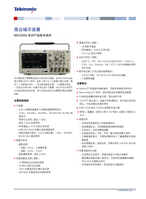
混合域示波器 - MDO3000 系列
带有 FastAcq 的数字荧光技术可以实现 > 280,000 wfm/s 的波形捕 获速率和实时颜色辉度等级。
触发 发现设备问题只是第一步,然后,您必须捕获关心的事件, 以确定根本原因。为了实现这一目标,MDO3000 系列含有 超过 125 种触发组合,提供了一套完整的触发功能,包括欠 幅脉冲触发、逻辑触发、脉宽 / 毛刺触发、建立时间 / 保持时 间违规触发、串行数据包触发和并行数据触发,帮助您迅速 找到关心的事件。由于具有高达 10 M 点的记录长度,您可 以在一次采集中捕获许多关心的事件,甚至包括数千个串行 数据包,以进一步进行分析,同时保持高分辨率,以放大观 察精细的信号细节。
自动测量读数提供了可重复的波形特点统计视图。
搜索步骤 2:Wave Inspector 自动搜索和记录每个事件,并用空心 白三角标记事件。然后可以使用 Previous 和 Next 按钮,从一个事件 跳到下一个事件。
每种测量均有帮助文本以及相关图形,帮助解释如何进行测量。
搜索步骤 3:搜索标记 (Search Mark) 表以表格视图呈现了通过自动 搜索所发现的每个事件。每个事件都显示有一个时间戳,在事件之 间方便地进行定时测量。
这些调色板可以迅速突出显示发生频次高的事件,在偶发异 常事件中,则会突出显示发生频次低的事件。
您可以选择无限余辉或可变余辉,确定波形在屏幕上停留多 长时间,进而可以确定异常事件的发生频次。
►► 3 GHz 和 6 GHz 集成频谱分析仪 ►► 同时采集模拟信号、数字信号和射频信号 ►► 20 M 记录长度 ►► 10.4 英寸 XGA 显示器
缩放和卷动
这个专用的两层前面板控件为缩放和卷动提供直观的控制。 内环控件调节缩放系数 ( 或缩放比例 ),顺时针旋转将激活缩 放并逐渐增大缩放系数,逆时针旋转将减小缩放系数,最终 可关闭缩放。您无需再去通过几个菜单来完成缩放显示。外 环控件在波形中卷动缩放框,以快速到达所关心的波形部分, 同时还利用力反馈来确定在波形中卷动的速度。外环控件旋 转得越快,缩放框移动得越快。只需向相反方向转动即可改 变卷动的方向。
泰克示波器安全操作及保养规程
泰克示波器安全操作及保养规程为了保障泰克示波器的正常使用和使用人员的人身安全,本文介绍泰克示波器的安全操作及保养规程。
1. 泰克示波器的操作安全规程1.1 电源相关1.插头应该牢固,不应该出现接触不良的情况。
2.正确使用电源线,不得使用已经磨损或被损坏的电源线。
3.在有危险环境下不能操作泰克示波器。
1.2 元器件安全相关1.对于使用时出现的异常,如:燃烧、发热等,应及时发现并断掉电源,停止使用。
2.对于泰克示波器的关键零部件,应更好地保存、更新或更换。
1.3 使用规程1.应当先打开电源,然后再开高压、高温启动过程。
2.正确阅读泰克示波器的使用说明书,根据说明书对泰克示波器的操作和使用进行操作。
3.不要使用过于粗鲁的方式来对泰克示波器进行操作,以免对设备造成损伤。
4.避免使用过长期、过大压力的操作,对于传感器的操作具有门槛。
1.4 环境安全1.在泰克示波器使用出现异常,如水、毫秒时间刻度等问题,应及时关机才能和更换零部件。
2.建议将泰克示波器放置在乾燥、通风的环境中进行操作,避免操作温度过低或温度过高。
2. 泰克示波器的保养规程泰克示波器即使不是经常性的使用,但是对设备保养的好处是不言而喻的。
2.1 泰克示波器的清洁1.在使用结束后,应将周边清洁得干净,避免设备因为周边的影响出现一些异样问题。
2.用软布或坚硬的纸巾擦拭泰克示波器、传感器等零部件时,擦拭前必须拔掉插头和电源线,注意安全。
2.2 泰克示波器的维修1.对于泰克示波器维修,应当联系泰克示波器的售后服务中心或技术服务部门;2.3 保持设备的干燥性1.应特别注意将泰克示波器存放在乾燥、开启通风良好的位置中;2.因为环境潮湿可能导致设备的电路板腐蚀等现象,对设备的损害会非常严重。
2.4 散热处理1.在设备运行过程中,容易产生起火、发热现象;2.如果设备操作时间过长、操作次数过多时,可能出现设备短时间内变得温度急涨的状况;3.对于设备的散热,应有相应的解决方式:在设备的散热后,将设备放在空旷的地方降温,或者在设备使用过程中将设备加工降温等操作。
初学者必须看看泰克示波器的入门使用方法

01示波器基本概念与原理Chapter示波器定义及作用01020304信号随时间变化的图形表示,如正弦波、方波、三角波等。
信号波形信号波形的最大和最小值之间的垂直距离,表示信号的强度。
幅度单位时间内信号波形重复的次数,表示信号的周期性。
频率描述信号波形相对于某一参考点的位置关系。
相位信号波形与参数示波器工作原理0102030402泰克示波器特点及优势Chapter高带宽高分辨率低噪声030201高性能指标分析多样化触发模式边沿触发脉宽触发模式触发强大数据处理能力实时FFT分析波形数学运算自动测量数据存储与导出03泰克示波器基本操作指南Chapter电源开关01亮度调节02聚焦调节03通道选择耦合方式选择垂直灵敏度调节水平时基调节触发源选择触发方式选择自动设置调用设置调用之前保存的设置,快速恢复示波器的配置。
将当前设置保存为默认设置或用户自定义设置,以便下次使用。
参数设置在子菜单下设置各种参数,如垂直灵敏度、水平时基、触发源、触发方式等。
主菜单通过前面板的按键或旋钮进入主菜单,进行各种设置和调整。
子菜单在主菜单下选择相应的子菜单,菜单设置与调整方法选择合适的触发源和触发方式,确保波形稳定将测量数据存储在示波器内部或通过接口导出到计算机进行进一步处数据存储与导出使用单次触发或自动触发模式,捕获瞬态或异常波形。
波形捕获波形分析使用双通道或多通道功能,同时显示多个信号,进行波形比较和分析。
波形比较0201030405波形显示与测量技巧04信号捕获、存储与回放功能详解Chapter信号捕获方式选择触发模式选择根据信号特点选择合适的触发模式,如边沿触发、脉宽触发等,确保信号稳定捕获。
触发电平设置调整触发电平,使其适应信号幅度,避免误触发或漏触发。
时基设置根据信号频率和所需观察的细节,选择合适的时基,以便在屏幕上显示完整的信号波形。
1 2 3存储格式选择存储深度设置数据压缩技术数据存储格式及大小设置01020304历史波形查看信号特性分析故障定位与诊断教学与演示回放功能应用举例05触发模式设置及优化建议Chapter触发模式类型介绍边沿触发脉宽触发模式触发触发条件设置方法选择触发源首先,用户需要选择触发的信号源,这通常是示波器的输入通道之一。