vhdl课程设计(电子钟+闹铃)
基于vhdl的电子闹钟设计
基于VHDL的数字闹钟设计摘要:随着EDA技术的发展和应用领域的扩大与深入,EDA技术在电子信息、通信、自动控制及计算机应用领域的重要性日益突出。
EDA技术就是依赖功能强大的计算机,在EDA工具软件平台上,对以硬件描述语言VHDL为系统逻辑描述手段完成的设计文件,自动地完成逻辑优化和仿真测试,直至实现既定的电子线路系统功能。
本文介绍了基于VHDL硬件描述语言设计的多功能数字闹钟的思路和技巧。
在Quart us11开发环境中编译和仿真了所设计的程序,并逐一调试验证程序的运行状况。
仿真和验证的结果表明,该设计方法切实可行,该数字闹钟可以实现调时定时闹钟播放音乐功能具有一定的实际应用性。
关键字:闹钟FPGA VHDLQuartus II一、电子钟相关功能描述如下:(1) 计时功能:这是本计时器设计的基本功能,可进行时、分、秒计时,并显示。
(2)闹钟功能:如果当前时间与设置的闹钟时间相同,则扬声器发出一段音乐,并维持一分钟。
(3) 调时调分调闹钟功能:当需要校时或者要重新设置闹钟的时间时,可通过实验箱上的按键控制。
二、设计原理:数字闹钟电路的基本结构由两个60进制计数器和一个24进制计数器组成,分别对秒、分、小时进行计时,当计时到23时59分59秒时,再来一个计数脉冲,则计数器清零,重新开始计时。
秒计数器的计数时钟CLK为1Hz的标准信号。
当数字闹钟处于计时状态时,秒计数器的进位输出信号作为分钟计数器的计数信号,分钟计数器的进位输出信号又作为小时计数器的计数信号时、分、秒的计时结果通过6个数码管来动态显示。
数字闹钟除了能够正常计时外,还应能够对时间进行调整。
因此,通过模式选择信号KEY1、KEY2控制数字钟的工作状态,即控制数字钟,使其分别工作于正常计时,调整分、时和设定闹钟分、时5个状态。
当数字闹钟处于计时状态时,3个计数器允许计数,且秒、分、时计数器的计数时钟信号分别为CLK,秒的进位,分的进位;当数字闹钟处于调整时间状态时,被调的分或时会一秒一秒地增加;当数字钟处于闹钟定时状态时,可以设定小时和分;当计时到所设定的时刻时,spea k将会被赋予梁祝音乐信号用于驱动扬声器,持续1分钟。
基于vhdl数字闹钟设计说明书

毕业设计(论文)论文题目:基于VHDL的数字闹钟设计所属系部:指导老师:职称:学生姓名:班级、学号:专业:毕业设计(论文)任务书题目:基于VHDL的数字闹钟设计任务与要求:设计一个带闹钟功能的24小时计时器。
完成功能:1.计时功能:每隔1分钟计时1次,并在显示屏上显示当前时间。
2.闹钟功能:如果当前时间与设置的闹钟时间相同,扬声器发出蜂鸣声。
时间:年月日至年月日共周所属系部:学生姓名:学号:专业:指导单位或教研室:指导教师:职称:毕业设计(论文)进度计划表本表作评定学生平时成绩的依据之一。
基于VHDL的数字闹钟设计【摘要】随着EDA技术的发展和应用领域的扩大与深入,EDA技术在电子信息、通信、自动控制及计算机应用领域的重要性日益突出。
EDA技术就是依赖功能强大的计算机,在EDA工具软件平台上,对以硬件描述语言VHDL为系统逻辑描述手段完成的设计文件,自动地完成逻辑优化和仿真测试,直至实现既定的电子线路系统功能。
本文介绍了基于VHDL硬件描述语言设计的多功能数字闹钟的思路和技巧。
在Quartus 11开发环境中编译和仿真了所设计的程序,并逐一调试验证程序的运行状况。
仿真和验证的结果表明,该设计方法切实可行,该数字闹钟可以实现调时定时闹钟功能具有一定的实际应用性。
关键词:数字闹钟 FPGA VHDL Quartus IIAbstract: With the EDA technology development and expansion of application fields and in-depth, EDA technology in the electronic information, communication, automatic control and computer applications of growing importance. EDA technology is dependent on a powerful computer, the software platform in the EDA tools for the hardware description language VHDL description for the system logic means completed design documents, automatically complete the test logic optimization and simulation, electronic circuit set up to achieve the system functionality. This article describes the VHDL hardware description language based on multi-function digital alarm clock design ideas and techniques. In the Quartus 11 compiler and development environment designed to simulate the process, and one by one to debug verification process operating conditions. Simulation and verification results show that the design method is feasible, digital alarm clock can adjust the time when the alarm clock to play music with some practical application.Key words: Alarm Clock FPGA VHDL Quartus II目录1 选题背景 (6)1.1选题研究内容 (6)1.2课题研究功能课题研究功能 (6)1.3课题相关技术应用 (6)2 FPGA 简介 (8)2.1FPGA概述 (8)2.2FPGA编程原理 (8)2.3FPGA设计流程 (9)3 总体设计思想 (10)3.1基本原理 (10)3.2设计框图 (10)4 设计步骤和调试过程 (11)4.1总体设计电路 (11)4.2模块设计和相应模块程序 (12)4.3仿真及仿真结果分析 (14)4.4实验调试结果 (15)结束语 (16)文献 (17)1 选题背景1.1 选题研究内容设计一个 24 小时的闹钟,该闹钟由显示屏、数字键、TIME 键、ALARM 键、扬声器组成。
基于VHDL的数字电子时钟的设计

目录基于VHDL的数字电子时钟的设计.............................................................. 错误!未定义书签。
目录 .. (1)摘要 (2)引言 (2)一、设计分析 (3)1.1 设计要求 (3)1.2 性能指标及功能设计性能指标 (3)二、设计方案 (3)三、设计环境 (4)3.1 硬件设计环境 (4)3.1.1 可编程器件EP2C5Q208C8N 及开发板系统 (5)3.1.2 64位的计算机一台 (5)3.2 软件设计环境 (5)3.2.1 QuartusⅡ软件开发平台(8.0版本) (5)3.2.2 Windows7操作系统 (5)3.2.3 硬件描述语言VHDL (5)四、整体设计流图 (7)4.1 各模块的原理性功能介绍 (7)4.1.1 可编程器件EP2C5Q208C8N (7)4.1.2 CPLD-JTAG接口 (7)4.1.3 晶振和蜂鸣器 (7)4.1.4 LED数码管显示 (8)4.1.5 独立按键 (9)4.1.6 拨码开关 (9)4.1.7 QuartusⅡ软件开发平台(8.0版本) (9)4.2 设计的整体框架 (10)4.2.1在各个模块都编译通过的基础上在顶层用原理图的方法实现。
(10)4.2.2 设计原理及流程图 (11)4.2.3逻辑流程图 (12)4.2.4状态转移图 (13)五、系统的模块化设计 (13)5.1 软件程序模块化设计 (13)5.1.1 秒/分/时输入模块的软件设计 (13)5.1.2 秒/分/时计数模块的软件设计 (14)5.1.3 模式选择模块的软件设计 (14)5.1.4 数码管 (15)5.1.5 闹钟模块的软件设计 (16)5.1.5 系统时钟的软件设计 (18)5.2 硬件的测试 (20)5.2.1模拟时钟电路图与实物图 (20)设计心得 (23)致谢 (24)参考文献 (24)摘要随着人类的不断进步,现代电子设计技术已进入一个全新的阶段,传统的电子设计方法、工具和器件在更大的程度上被EDA所取代。
电子时钟课程设计--基于VHDL的电子钟的设计
电子技术课程设计题目基于VHDL的电子钟的设计学院名称电气工程学院指导教师 XXX职称教授班级电力XXX班学号 2007XXX学生姓名XXX2010年 01 月 15 日课程设计任务书学院电气工程学院专业电气工程及其自动化班级电力XXX班学号 2007XXXXXXX姓名 XXX 指导老师 XXX一设计课题名称基于VHDL的电子钟的设计二电子钟功能本课题要求所设计的电子钟能够正常进行时、分、秒计时,并显示计时结果。
同时具有校时功能。
三设计要求1.详细说明设计方案;2.用VHDL编写设计程序;3.给出系统仿真结果;4.进行硬件验证。
目录第一章1.1引言----------------------------------------------------------------4 1.2 课题设计的背景、目的---------------------------------------4第二章2.1 EDA的简单介绍------------------------------------------------ 6 2.2 VHDL的简单介绍----------------------------------------------- 6 2.3 Quartus2 软件----------------------------------------------- 7 第三章3.1电子钟的结构图--------------------------------------------------9 3.2小时模块------------------------------------------------ 9 3. 3分钟模块---------------------------------------------- 11 3.4 秒钟模块-------------------------------------------12 3.5 时间设置模块--------------------------------------------- 14 心得体会------------------------------------------------------------17参考文献------------------------------------------------------------18第一章1.1 引言随着科学技术的不断发展,人们对时间计量的精度要求越来越高。
vhdl课程设计(电子钟+闹铃)
数字钟的设计一.体系功效概述(一).体系实现的功效:1.具有“时”.“分”.“秒”的十进制数字显示(小时从00~ 23).2.具有手动校时.校分.校秒的功效.3.有准时和闹钟功效,可以或许在设定的时光发出闹铃声.4.能进行整点报时.从59分50秒起,每隔2秒发一次低音“嘟”的旌旗灯号,持续5次,最后一次为高音“嘀”的旌旗灯号.(二).各项设计指标:1.显示部分采取的6个LED显示器,从高位至低位分离显示时.分.秒.2.有一个设置调闹钟准不时光.正常时光的按钮,选择调的对象.3.有三个按钮分离调时.分.秒的时光.4.有一个按钮用作开启/封闭闹铃.5.别的须要两个时钟旌旗灯号来给体系供给脉冲旌旗灯号,使时钟和闹钟正常工作,分离为1Hz.1kHz的脉冲.二.体系构成以及体系各部分的设计1.体系构造描写//请求:体系(或顶层文件)构造描写,各个模块(或子程序)的功效描写;(一)体系的顶层文件:1、顶层文件图:(见下页)2、各模块的解释:(1).7个输入量clk_1khz.clk_1hz.key_slt.key_alarm.sec_set.min_set.hou r_set:个中clk_1khz为闹铃模块供给时钟,处理后能产生“嘟”.“嘀”和变更的闹铃声音;clk_1hz为计时模块供给时钟旌旗灯号,每秒计数一次;key_slt选择设置对象:准时或正常时光;key_alarm可以或许开启和封闭闹铃;sec_set.min_set.hour_set用于设置时光或准时,与key_slt相联系关系.各按键输出为脉冲旌旗灯号.(2).CNT60_A_SEC模块:这个模块式将clk_1hz这个时钟旌旗灯号进行60进制计数,并产生一个分钟的触发旌旗灯号.该模块能将当前计数值及时按BCD码的格局输出.将该输出接到两位LED数码后能不时显示秒的状况.经由过程alarm_clk可以选择设置对象为时光照样准时价.在设置时光模式上,key上的一个输入脉冲可以将clk的输入旌旗灯号加一.在设置准时模式上,key上的脉冲只修正准时价,不影响时光脉冲clk的状况.同时该模块具有两个输出口out_do.out_di来触发整点报时的“嘟”.“嘀”声音.(3).CNT60_A_MIN模块:这个模块式将CNT60_A_SEC的输出旌旗灯号进行60进制计数,并产生一个时位的触发旌旗灯号.该模块能将当前计数值及时按BCD码的格局输出.将该输出接到两位LED数码后能不时显示分的状况.经由过程alarm_clk可以选择设置对象为时光照样准时价.在设置时光模式上,key上的一个输入脉冲可以将clk的输入旌旗灯号加一.在设置准时模式上,key上的脉冲只修正准时价,不影响时光脉冲clk的状况.同时该模块具有三个输出口out_do.out_di.out_alarm来触发整点报时的“嘟”.“嘀”.闹铃声音.(4).CNT24_A_HOUR模块:这个模块式将CNT60_A_MIN的输出旌旗灯号做24进制计数.该模块能将当前计数值及时按BCD码的格局输出.将该输出接到两位LED数码后能不时显示时的状况.经由过程alarm_clk 可以选择设置对象为时光照样准时价.在设置时光模式上,key 上的一个输入脉冲可以将clk的输入旌旗灯号加一.在设置准时模式上,key上的脉冲只修正准时价,不影响时光脉冲clk的状况.同时该模块具有一个输出口out_alarm来触发整点报时的闹铃声音.(5).PWM_OUT模块:该模块为PWM产生模块,经由过程EN可开启和封闭PWM输出.模块依据CLK旌旗灯号二分频产生的高下音,并组合,能输出三种声音状况——“嘟”.“嘀”.闹铃.而该三种声音要被秒.分.时的输出触发才干输出PWM.(二)体系各个模块的VHDL程序:(1).CNT60_A_SEC模块:程序源代码如下:library ieee;use ieee.std_logic_1164.all;use ieee.std_logic_unsigned.all;entity cnt60_a_sec isport(clk,clr,enb: in std_logic;--clk:时钟输入旌旗灯号,clr:清零端,enb:使能端key: in std_logic;--输入按键脉冲,调剂闹铃准时或时光alarm_clk: in std_logic;--1:alarm 0:clk--设置模式选择:闹铃调节模式.时光调节模式qout_sl: out std_logic_vector(3 downto 0); --显示输出秒的低位qout_sh: out std_logic_vector(3 downto 0);--显示输出秒的高位co: out std_logic; --进位输出,触发分计数模块out_do: out std_logic;--在整点报时中输出“嘟”触发旌旗灯号out_di: out std_logic --在整点报时中输出“嘀”触发旌旗灯号);end;architecture a of cnt60_a_sec issignal qout2_l:std_logic_vector(3 downto 0);signal qout2_h:std_logic_vector(3 downto 0);signal alarm_l:std_logic_vector(3 downto 0);signal alarm_h:std_logic_vector(3 downto 0);signal clk1,clk2,tclk,aclk,ac_slt: std_logic;beginprocess(alarm_clk) --当该端口输入一个脉冲时,修正设置模式:时光调剂或闹铃模式切换beginif alarm_clk'event and alarm_clk='1' thenif ac_slt='0' then--假如为准时模式,将改为闹铃模式ac_slt<='1';elseac_slt<='0';end if;end if;end process;process(key,clk,ac_slt)--依据设置模式,处理key上的脉冲旌旗灯号beginif ac_slt='0' then --时光调剂模式aclk<='0';if clk='1' and key='1' then --clk=1则tclk<=0,经由过程挖洞方法添加一个脉冲tclk<='0';elsif clk='0' and key='1' then --clk=0,则tclk<=1,产生一个高电平,添加一脉冲tclk<='1';elsetclk<=clk;end if;elsif ac_slt='1' then --闹铃调剂模式tclk<=clk;aclk<=key; --key上的脉冲直接修正闹铃准时价end if;end process;process(tclk,clr,enb) --60进制计数,个位.十位放在两个暂时变量中,暗示秒的状况beginif clr='1' then--clearing works at the state of high voltageqout2_l<="0000";qout2_h<="0000";elsif tclk'event and tclk='1' thenif enb='1' then--enable works at high voltageif qout2_l="1001" and qout2_h="0101" thenqout2_l<="0000";--a full mode is completed and a carryout is generatedqout2_h<="0000";elsif qout2_l="1001" thenqout2_l<="0000";qout2_h<=qout2_h+1;elseqout2_l<=qout2_l+1;-- in process of countingend if;end if;end if;end process;process(aclk,clr,enb)--修正闹铃的准时价if clr='1' then--clearing works at the state of high voltagealarm_l<="0000";alarm_h<="0000";elsif aclk'event and aclk='1' thenif enb='1' then--enable works at high voltageif alarm_l="1001" and alarm_h="0101" thenalarm_l<="0000";--a full mode is completed and a carryout is generatedalarm_h<="0000";elsif alarm_l="0101" thenalarm_l<="0000";alarm_h<=alarm_h+1;elsealarm_l<=alarm_l+1;-- in process of countingend if;end if;end if;end process;process(qout2_l,qout2_h,alarm_l,alarm_h,alarm_clk)-- 产生进位,显示时光或闹铃准时价if qout2_l="0000" and qout2_h="0000" thenco<='1';elseco<='0';end if;if ac_slt='0' then -- 显示时光qout_sl<=qout2_l;qout_sh<=qout2_h;else -- 显示准时价qout_sh<=alarm_h;qout_sl<=alarm_l;end if;end process;process(qout2_l,qout2_h) -- 依据秒的状况输出“嘟”.“嘀”触发旌旗灯号beginif qout2_h="0101" thenif qout2_l="0000" thenout_do<='1';elsif qout2_l="0010" thenout_do<='1';elsif qout2_l="0100" then out_do<='1';elsif qout2_l="0110" then out_do<='1';elsif qout2_l="1000" then out_do<='1';elseout_do<='0';end if;elsif qout2_h="0000" then if qout2_l="0000" then out_di<='1';out_do<='0';elseout_di<='0';end if;elseout_do<='0';out_di<='0';end if;end process;end;(2).CNT60_A_MIN模块:library ieee;use ieee.std_logic_1164.all;use ieee.std_logic_unsigned.all;entity cnt60_a_min isport(clk,clr,enb: in std_logic;--clk:时钟输入旌旗灯号,clr:清零端,enb:使能端key: in std_logic;--输入按键脉冲,调剂闹铃准时或时光alarm_clk: in std_logic;--1:alarm 0:clk--设置模式选择:闹铃调节模式.时光调节模式qout_ml: out std_logic_vector(3 downto 0);--显示输出分的低位qout_mh: out std_logic_vector(3 downto 0);--显示输出分的高位co: out std_logic; --进位输出,触发时计数模块out_alarm:out std_logic;--闹铃触发旌旗灯号,时光到后输出高电平触发闹铃out_do,out_di: out std_logic--在整点报时中输出“嘟”“嘀”触发旌旗灯号);end;architecture a of cnt60_a_min issignal qout2_l:std_logic_vector(3 downto 0);signal qout2_h:std_logic_vector(3 downto 0);signal alarm_l:std_logic_vector(3 downto 0);signal alarm_h:std_logic_vector(3 downto 0);signal clk1,clk2,tclk,aclk,ac_slt: std_logic;beginprocess(alarm_clk)--当该端口输入一个脉冲时,修正设置模式:时光调剂或闹铃模式切换beginif alarm_clk'event and alarm_clk='1' thenif ac_slt='0' then--假如为准时模式,将改为闹铃模式ac_slt<='1';elseac_slt<='0';end if;end if;end process;process(key,clk,ac_slt)--依据设置模式,处理key上的脉冲旌旗灯号beginif ac_slt='0' then --时光调剂模式aclk<='0';if clk='1' and key='1' then--clk=1则tclk<=0,经由过程挖洞方法添加一个脉冲tclk<='0';elsif clk='0' and key='1' then--clk=0,则tclk<=1,产生一个高电平,添加一脉冲tclk<='1';elsetclk<=clk;end if;elsif ac_slt='1' then --闹铃调剂模式tclk<=clk;aclk<=key;--key上的脉冲直接修正闹铃准时价end if;end process;process(tclk,clr,enb) --60进制计数,个位.十位放在两个暂时变量中,暗示分的状况beginif clr='1' then--clearing works at the state of high voltageqout2_l<="0000";qout2_h<="0000";elsif tclk'event and tclk='1' thenif enb='1' then--enable works at high voltageif qout2_l="1001" and qout2_h="0101" thenqout2_l<="0000";--a full mode is completed and a carryout is generatedqout2_h<="0000";elsif qout2_l="1001" thenqout2_l<="0000";qout2_h<=qout2_h+1;elseqout2_l<=qout2_l+1;-- in process of countingend if;end if;end if;end process;process(aclk,clr,enb)--修正闹铃的准时价beginif clr='1' then--clearing works at the state of high voltagealarm_l<="0000";alarm_h<="0000";elsif aclk'event and aclk='1' thenif enb='1' then--enable works at high voltageif alarm_l="1001" and alarm_h="0101" thenalarm_l<="0000";--a full mode is completed and a carryout is generatedalarm_h<="0000";elsif alarm_l="0101" thenalarm_l<="0000";alarm_h<=alarm_h+1;elsealarm_l<=alarm_l+1;-- in process of countingend if;end if;end if;end process;process(qout2_l,qout2_h,alarm_l,alarm_h,alarm_clk)-- 产生进位,显示时光或闹铃准时价of high voltagebeginif qout2_l="0000" and qout2_h="0000" thenco<='1';elseco<='0';end if;if ac_slt='0' thenqout_ml<=qout2_l;qout_mh<=qout2_h;elseqout_mh<=alarm_h;qout_ml<=alarm_l;end if;end process;process(qout2_l,qout2_h,alarm_l,alarm_h)–断定准时价与时光值相等,输出闹铃触发旌旗灯号beginif qout2_l=alarm_l and qout2_h=alarm_h thenout_alarm<='1';elseout_alarm<='0';end if;end process;process(qout2_l,qout2_h)-- 依据分的状况输出“嘟”.“嘀”触发旌旗灯号beginif qout2_l="1001" and qout2_h="0101" thenout_do<='1';elseout_do<='0';end if;if qout2_l="0000" and qout2_h="0000" thenout_di<='1';elseout_di<='0';end if;end process;end;(3).CNT24_A_HOUR模块:library ieee;use ieee.std_logic_1164.all;use ieee.std_logic_unsigned.all;entity cnt24_a_hour isport(clk,clr,enb: in std_logic;--clk:时钟输入旌旗灯号,clr:清零端,enb:使能端key: in std_logic;--输入按键脉冲,调剂闹铃准时或时光alarm_clk: in std_logic;--1:alarm 0:clk--设置模式选择:闹铃调节模式.时光调节模式qout_hl: out std_logic_vector(3 downto 0);--显示输出时的低位qout_hh: out std_logic_vector(3 downto 0);--显示输出时的高位co: out std_logic;--进位输出out_alarm:out std_logi--闹铃触发旌旗灯号输出);end;architecture a of cnt24_a_hour issignal qout2_l:std_logic_vector(3 downto 0);signal qout2_h:std_logic_vector(3 downto 0);signal alarm_l:std_logic_vector(3 downto 0);signal alarm_h:std_logic_vector(3 downto 0);signal clk1,clk2,tclk,aclk,ac_slt: std_logic;beginprocess(alarm_clk)--当该端口输入一个脉冲时,修正设置模式:时光调剂或闹铃模式切换beginif alarm_clk'event and alarm_clk='1' thenif ac_slt='0' then--假如为准时模式,将改为闹铃模式ac_slt<='1';elseac_slt<='0';end if;end if;end process;process(key,clk,ac_slt)--依据设置模式,处理key上的脉冲旌旗灯号beginif ac_slt='0' then --时光调剂模式aclk<='0';if clk='1' and key='1' then--clk=1则tclk<=0,经由过程挖洞方法添加一个脉冲tclk<='0';elsif clk='0' and key='1' then--clk=0,则tclk<=1,产生一个高电平,添加一脉冲tclk<='1';elsetclk<=clk;end if;elsif ac_slt='1' then --闹铃调剂模式tclk<=clk;aclk<=key; --key上的脉冲直接修正闹铃准时价end if;end process;process(tclk,clr,enb)--24进制计数,个位.十位放在两个暂时变量中,暗示时的状况beginif clr='1' then--clearing works at the state of high voltageqout2_l<="0000";qout2_h<="0000";elsif tclk'event and tclk='1' thenif enb='1' then--enable works at high voltageif qout2_l="1001" thenqout2_l<="0000";--a full mode is completed and a carryout is generatedqout2_h<=qout2_h+1;elsif qout2_l="0011" and qout2_h="0010" thenqout2_l<="0000";qout2_h<="0000";elseqout2_l<=qout2_l+1;-- in process of countingend if;end if;end if;end process;process(aclk,clr,enb)--修正闹铃的准时价beginif clr='1' then--clearing works at the state of high voltagealarm_l<="0000";alarm_h<="0000";elsif aclk'event and aclk='1' thenif enb='1' then--enable works at high voltageif alarm_l="1001" thenalarm_l<="0000";--a full mode is completed and a carryout is generatedalarm_h<=qout2_h+1;elsif alarm_l="0011" and alarm_h="0010" thenalarm_l<="0000";alarm_h<="0000";elsealarm_l<=alarm_l+1;-- in process of countingend if;end if;end if;end process;process(qout2_l,qout2_h,alarm_l,alarm_h,alarm_clk)-- 产生进位,显示时光或闹铃准时价of high voltagebeginif qout2_l="0000" and qout2_h="0000" thenco<='1';elseco<='0';end if;if ac_slt='0' thenqout_hl<=qout2_l;qout_hh<=qout2_h;elseqout_hh<=alarm_h;qout_hl<=alarm_l;end if;end process;process(qout2_l,qout2_h,alarm_l,alarm_h)--准时价与时光值相等,则输出闹钟触发旌旗灯号beginif qout2_l=alarm_l and qout2_h=alarm_h thenout_alarm<='1';elseout_alarm<='0';end if;end process;end;2.体系以及各个模块的仿真波形(1).体系仿真波形:注:因为下面的模块仿真消失毛刺,导致体系的仿真图有必定的问题.(2).CNT60_A_SEC模块:注:在50.52.54.56.58处有嘟触发输出,00处有嘀触发输出等.(3).CNT60_A_MIN模块:注:本图展现了按键调节时光值和准时价的仿真波形(部分仿真图).注:该模块的仿真波形图,具有嘟.嘀声音触发输出,准时与时光相等时有闹铃触发输出等.(4).CNT24_A_HOUR模块注:该模块的仿真图,包含按键调剂时光.准时价,闹钟触发输出等.(5).PWM_OUT模块(分三段剪切下来的,展现了三种声音的后果)(1).“嘟”.“嘀”输出波形(只有在en有脉冲,打开PWMO后,才有用)注:在打开输出后,当两路嘟.嘀触发输入同时有用时分离输出嘟.嘀声音.当两路闹铃触发同时有用时开端闹铃声音的输出.注:闹铃输出的变更情形(“嘀”.“嘟”瓜代发声).注:闹铃输出的变更情形.3.下载时选择的开辟体系模式以及管脚界说表1 GW48-CK开辟体系工作模式:3三.课程设计过程中碰到的问题以及解决办法主如果在“调剂时光”和“调剂准时”的上面碰到异常大的艰苦.与开端想象的不一样,一个过程中不克不及参加时钟旌旗灯号,没可以或许将按键脉冲直接与时钟脉冲进行累加.同时,在对VHDL的语法的熟习上也消费了大量的时光.最后的解决办法是,经由过程另一个过程,先将这两个旌旗灯号进行处理后,分离产生aclk和tclk分离为准时调剂部分.和时光调剂部分供给时钟旌旗灯号.调剂按键的脉冲旌旗灯号和正常的时钟旌旗灯号不是按照简略的或运算来处理的.1).假如要调剂时光:1、当时钟旌旗灯号是高电平,按键旌旗灯号也是高电日常平凡,则给tclk赋值0.2、当时钟旌旗灯号是高电平,按键旌旗灯号是低电日常平凡,则给tclk赋值1.3、当时钟旌旗灯号是低电平,按键旌旗灯号是高电日常平凡,则给tclk赋值1.4、当时钟旌旗灯号是低电平,按键旌旗灯号是低电平是,则给tclk赋值0.如许无论按键脉冲是在高电平照样低电平,或者是在高下电平两种状况下消失,其最终成果都是会多产生一个脉冲旌旗灯号,导致计数值变更,达到修正时光的目标.时代,aclk始终不变.2).假如要调剂准时:1.时钟输入旌旗灯号赋值给tclk2.按键输入旌旗灯号赋值给aclk如许,当按键脉冲停止时,准时调剂旌旗灯号会消失一个脉冲.而时钟旌旗灯号不受影响.别的,在闹铃产生上也碰到了一些小问题,最后,经由过程在产生周期较长的旌旗灯号,切换输出值的内容“嘟”还有“嘀”,最后的后果就是“嘟”.“嘀”声音瓜代发出.在仿真时,大多半模块会消失毛刺,会导致最后的总仿真成果不是很乐不雅,会评脉冲的几个干扰加上去.这方面,我试图调了良久也没解决.不过因为在现实下载后照样相比较较正常的,仿真中的毛刺最后没有清除失落.。
电子秒表设计VHDL

一、设计题目:基于VHDL语言的电子秒表设计(可调时,有闹钟、定时功能)二、设计目的:⑴掌握较复杂的逻辑设计和调试⑵学习用原理图+VHDL语言设计逻辑电路⑶学习数字电路模块层次设计⑷掌握QuartusII软件及Modelsim软件的使用方法三、设计内容:(一)设计要求1、具有以二十四小时计时、显示、整点报时、时间设置和闹钟的功能。
2、设计精度要求为1S。
(二).系统功能描述1 . 系统输入:系统状态及校时、定时转换的控制信号为k、set、ds;时钟信号clk,采用实验箱的50MHz;系统复位信号为reset。
输入信号均由按键产生。
系统输出:8位LED七段数码管显示输出,蜂鸣器声音信号输出。
多功能数字钟系统功能的具体描述如下:2. 计时:set=1,ds=1工作状态下,每日按24h计时制计时并显示,蜂鸣器无声,逢整点报时。
3. 校时:在set=0,ds=0状态下,按下“k键”,进入“小时”校准状态,之后按下“k键”则进入“分”校准状态,继续按下“k键”则进入“秒校准”状态,之后如此循环。
1)“小时”校准状态:在“小时”校准状态下,显示“小时”数码管以1Hz的频率递增计数。
2)“分”校准状态:在“分”校准状态下,显示“分”的数码管以1Hz的频率递增计数。
3)“秒”复零状态:在“秒复零”状态下,显示“分”的数码管以1Hz的频率递增计数。
4. 整点报时:蜂鸣器在“59”分钟的第50—59,以1秒为间隔分别发出1000Hz,500Hz的声音。
5. 显示:采用扫描显示方式驱动8个LED数码管显示小时、分、秒。
闹钟:闹钟定时时间到,蜂鸣器发出交替周期为1s的1000Hz、500Hz的声音,持续时间为一分钟;6. 闹钟定时设置:在set=0,ds=1状态下,按下“k”,进入闹钟的“时”设置状态,之后按下“k键”进入闹钟的“分”设置状态,继续按下“k 键”则进入“秒”设置状态, 之后如此循环。
1)闹钟“小时”设置状态:在闹钟“小时”设置状态下,显示“小时”的数码管以1Hz 的频率递增计数。
数字钟的设计课程设计VHDL
数字钟的设计 课程设计 VHDL一、课程目标知识目标:1. 理解数字时钟的基本原理和VHDL语言编程基础;2. 学会使用VHDL语言设计简单的数字时钟电路;3. 掌握数字时钟各模块的功能及其相互关系;4. 了解数字时钟在实际应用中的重要性。
技能目标:1. 能够运用VHDL语言编写简单的数字时钟程序;2. 能够对设计的数字时钟进行功能仿真和时序分析;3. 能够根据实际需求调整和优化数字时钟设计;4. 培养学生的团队协作能力和问题解决能力。
情感态度价值观目标:1. 培养学生对数字电路设计和VHDL编程的兴趣和热情;2. 增强学生对我国集成电路产业的认识,提高国家自豪感;3. 培养学生严谨、认真、负责的学习态度,为未来从事相关工作奠定基础。
课程性质:本课程为电子信息类专业的实践课程,旨在帮助学生掌握数字时钟设计的基本方法和技能。
学生特点:学生已具备一定的数字电路基础和VHDL编程知识,具有一定的自学能力和动手能力。
教学要求:结合学生特点,注重理论与实践相结合,强化实践操作,鼓励学生创新和团队协作。
通过本课程的学习,使学生能够独立完成数字时钟的设计与实现,达到学以致用的目的。
二、教学内容1. 数字时钟原理概述:数字时钟的组成、工作原理和性能指标;2. VHDL语言基础:VHDL程序结构、数据类型、运算符、顺序语句和并行语句;3. 数字时钟设计方法:分频器、计数器、秒表、时钟显示等模块的设计原理和实现方法;4. 数字时钟电路仿真:功能仿真和时序分析,优化设计;5. 数字时钟综合设计:根据实际需求,完成数字时钟的各个模块设计和整体集成;6. 数字时钟实践操作:动手实践,调试和优化数字时钟设计。
教学大纲安排:第一周:数字时钟原理概述,VHDL语言基础;第二周:数字时钟各个模块的设计方法;第三周:数字时钟电路仿真,功能验证;第四周:数字时钟综合设计,实践操作。
教学内容关联教材章节:1. 数字时钟原理概述:第三章 数字电路基础;2. VHDL语言基础:第四章 VHDL硬件描述语言;3. 数字时钟设计方法:第五章 数字系统设计;4. 数字时钟电路仿真:第六章 数字电路仿真;5. 数字时钟综合设计:第五章 数字系统设计;6. 数字时钟实践操作:实验指导书相关内容。
基于VHDL的自动打铃设计_毕业设计 精品
基于VHDL的自动打铃设计目录摘要 (1)Abstract (2)绪论 (3)第1章基本概念简介 (4)1.1 VHDL简介 (4)1.2 FPGA/CPLD简介 (4)1.3 Quartus II的简介 (5)第2章设计整体概述 (6)2.1 设计方案 (6)2.2 设计原理图 (6)2.3 设计流程图 (7)第3章各模块设计分析 (8)3.1 计数器模块 (8)3.1.1 秒和分计数器模块 (8)3.1.2 时计数器模块 (10)3.2 计时校时模块 (12)3.3 打铃功能模块 (13)3.4 顶层设计及原理图 (16)第4章引脚设定与下载验证 (19)4.1 引脚设定 (19)4.2 下载验证 (21)总结 (22)参考文献 (23)致谢............................................ (错误!未定义书签。
) 附录芯片引脚对照表.. (25)摘要随着EDA 技术的发展和应用领域的扩大与深入,EDA 技术在电子信息、通信、自动控制及计算机应用领域的重要性日益突出。
EDA 技术就是以计算机为工具,设计者在EDA软件平台上,对以硬件描述语言HDL(Hardware Description language)为系统逻辑描述手段完成的设计文件,然后由计算机自动地完成逻辑编译、化简、分割、综合、优化、布局、布线和仿真,直至对于特定目标芯片的适配编译、逻辑映射和编程下载等工作。
本设计是基于VHDL语言的自动打铃系统。
在论文中,介绍了基于VHDL语言自动打铃系统的思路,整个系统需包含秒计时模块、分计时模块、时计时模块、校时模块、打铃模块。
在Quartus II 开发环境中编译和仿真所设计的程序,并逐一调试验证程序的运行状况。
仿真和验证的结果表明,该设计方法切实可行,该打铃系统可以实现调时定时打铃功能,具有一定的实际应用性。
关键字:EDA、VHDL、打铃、Quartus IIAbstractWith the development of EDA technology and the expansion of application, the function of EDA technology in the field of electronic information communication, automatic control and computer application, is becoming more and more important. EDA technology use computer as a tool. However, designers only need to use the hardware description language HDL to describe the system on the EDA software platform. Then computer automatically finishes partition, synthesis, optimization, simulation and other function until the electronic circuit system achieves the stated performance.This design is based on the VHDL hardware description language to project a system. I introduce ideas of the bell system in this design. All of the design includes second timer module, minute timer module, hour timer module, module to adjust time and module to ring the bell according to the require of design. I complete the description of different modules with VHDL language in the Quartus II development environment, and debug one by one to check the operational status of the verification process. Simulation results show that the design method is feasible, and the bell system can be put into practical applications.Keywords: EDA, VHDL, rang the bell, the Quartus II绪论随着EDA 技术的发展和应用领域的扩大与深入,EDA 技术在电子信息、通信、自动控制及计算机应用领域的重要性日益突出。
- 1、下载文档前请自行甄别文档内容的完整性,平台不提供额外的编辑、内容补充、找答案等附加服务。
- 2、"仅部分预览"的文档,不可在线预览部分如存在完整性等问题,可反馈申请退款(可完整预览的文档不适用该条件!)。
- 3、如文档侵犯您的权益,请联系客服反馈,我们会尽快为您处理(人工客服工作时间:9:00-18:30)。
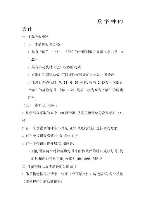
数字钟的设计一、系统功能概述(一)、系统实现的功能:1、具有“时”、“分”、“秒”的十进制数字显示(小时从00 ~ 23)。
2、具有手动校时、校分、校秒的功能。
3、有定时和闹钟功能,能够在设定的时间发出闹铃声。
4、能进行整点报时。
从59分50秒起,每隔2秒发一次低音“嘟”的信号,连续5次,最后一次为高音“嘀”的信号。
(二)、各项设计指标:1、显示部分采用的6个LED显示器,从高位至低位分别显示时、分、秒。
2、有一个设置调闹钟定时时间、正常时间的按钮,选择调的对象。
3、有三个按钮分别调时、分、秒的时间。
4、有一个按钮用作开启/关闭闹铃。
5、另外需要两个时钟信号来给系统提供脉冲信号,使时钟和闹钟正常工作,分别为1Hz、1kHz的脉冲。
二、系统组成以及系统各部分的设计1、系统结构描述//要求:系统(或顶层文件)结构描述,各个模块(或子程序)的功能描述;(一)系统的顶层文件:1、顶层文件图:(见下页)2、各模块的解释:(1)、7个输入量clk_1khz、clk_1hz、key_slt、key_alarm、sec_set、min_set、hour_set:其中clk_1khz为闹铃模块提供时钟,处理后能产生“嘟”、“嘀”和变化的闹铃声音;clk_1hz为计时模块提供时钟信号,每秒计数一次;key_slt选择设置对象:定时或正常时间;key_alarm能够开启和关闭闹铃;sec_set、min_set、hour_set用于设置时间或定时,与key_slt相关联。
各按键输出为脉冲信号。
(2)、CNT60_A_SEC模块:这个模块式将clk_1hz这个时钟信号进行60进制计数,并产生一个分钟的触发信号。
该模块能将当前计数值实时按BCD码的格式输出。
将该输出接到两位LED数码后能时时显示秒的状态。
通过alarm_clk可以选择设置对象为时间还是定时值。
在设置时间模式上,key上的一个输入脉冲可以将clk的输入信号加一。
在设置定时模式上,key 上的脉冲只修改定时值,不影响时间脉冲clk的状态。
同时该模块具有两个输出口out_do、out_di来触发整点报时的“嘟”、“嘀”声音。
(3)、CNT60_A_MIN模块:这个模块式将CNT60_A_SEC的输出信号进行60进制计数,并产生一个时位的触发信号。
该模块能将当前计数值实时按BCD码的格式输出。
将该输出接到两位LED数码后能时时显示分的状态。
通过alarm_clk可以选择设置对象为时间还是定时值。
在设置时间模式上,key上的一个输入脉冲可以将clk的输入信号加一。
在设置定时模式上,key上的脉冲只修改定时值,不影响时间脉冲clk的状态。
同时该模块具有三个输出口out_do、out_di、out_alarm来触发整点报时的“嘟”、“嘀”、闹铃声音。
(4)、CNT24_A_HOUR模块:这个模块式将CNT60_A_MIN的输出信号做24进制计数。
该模块能将当前计数值实时按BCD码的格式输出。
将该输出接到两位LED数码后能时时显示时的状态。
通过alarm_clk可以选择设置对象为时间还是定时值。
在设置时间模式上,key上的一个输入脉冲可以将clk的输入信号加一。
在设置定时模式上,key上的脉冲只修改定时值,不影响时间脉冲clk的状态。
同时该模块具有一个输出口out_alarm来触发整点报时的闹铃声音。
(5)、PWM_OUT模块:该模块为PWM产生模块,通过EN可开启和关闭PWM输出。
模块根据CLK信号二分频产生的高低音,并组合,能输出三种声音状态——“嘟”、“嘀”、闹铃。
而该三种声音要被秒、分、时的输出触发才能输出PWM。
(二)系统各个模块的VHDL程序:(1)、CNT60_A_SEC模块:程序源代码如下:library ieee;use ieee.std_logic_1164.all;use ieee.std_logic_unsigned.all;entity cnt60_a_sec isport(clk,clr,enb: in std_logic;--clk:时钟输入信号,clr:清零端,enb:使能端key: in std_logic; --输入按键脉冲,调整闹铃定时或时间alarm_clk: in std_logic;--1:alarm 0:clk --设置模式选择:闹铃调节模式、时间调节模式qout_sl: out std_logic_vector(3 downto 0); --显示输出秒的低位qout_sh: out std_logic_vector(3 downto 0);--显示输出秒的高位co: out std_logic; --进位输出,触发分计数模块out_do: out std_logic;--在整点报时中输出“嘟”触发信号out_di: out std_logic --在整点报时中输出“嘀”触发信号);end;architecture a of cnt60_a_sec issignal qout2_l:std_logic_vector(3 downto 0);signal qout2_h:std_logic_vector(3 downto 0);signal alarm_l:std_logic_vector(3 downto 0);signal alarm_h:std_logic_vector(3 downto 0);signal clk1,clk2,tclk,aclk,ac_slt: std_logic;beginprocess(alarm_clk) --当该端口输入一个脉冲时,修改设置模式:时间调整或闹铃模式切换beginif alarm_clk'event and alarm_clk='1' thenif ac_slt='0' then--如果为定时模式,将改为闹铃模式ac_slt<='1';elseac_slt<='0';end if;end if;end process;process(key,clk,ac_slt)--根据设置模式,处理key上的脉冲信号beginif ac_slt='0' then --时间调整模式aclk<='0';if clk='1' and key='1' then --clk=1则tclk<=0,通过挖洞方式添加一个脉冲tclk<='0';elsif clk='0' and key='1' then --clk=0,则tclk<=1,产生一个高电平,添加一脉冲tclk<='1';elsetclk<=clk;end if;elsif ac_slt='1' then --闹铃调整模式tclk<=clk;aclk<=key; --key上的脉冲直接修改闹铃定时值end if;end process;process(tclk,clr,enb) --60进制计数,个位、十位放在两个临时变量中,表示秒的状态beginif clr='1' then--clearing works at the state of high voltageqout2_l<="0000";qout2_h<="0000";elsif tclk'event and tclk='1' thenif enb='1' then--enable works at high voltageif qout2_l="1001" and qout2_h="0101" thenqout2_l<="0000";--a full mode is completed and a carryout is generatedqout2_h<="0000";elsif qout2_l="1001" thenqout2_l<="0000";qout2_h<=qout2_h+1;elseqout2_l<=qout2_l+1;-- in process of countingend if;end if;end if;end process;process(aclk,clr,enb)--修改闹铃的定时值beginif clr='1' then--clearing works at the state of high voltagealarm_l<="0000";alarm_h<="0000";elsif aclk'event and aclk='1' thenif enb='1' then--enable works at high voltageif alarm_l="1001" and alarm_h="0101" thenalarm_l<="0000";--a full mode is completed and a carryout is generatedalarm_h<="0000";elsif alarm_l="0101" thenalarm_l<="0000";alarm_h<=alarm_h+1;elsealarm_l<=alarm_l+1;-- in process of countingend if;end if;end if;end process;process(qout2_l,qout2_h,alarm_l,alarm_h,alarm_clk)-- 产生进位,显示时间或闹铃定时值beginif qout2_l="0000" and qout2_h="0000" thenco<='1';elseco<='0';end if;if ac_slt='0' then -- 显示时间qout_sl<=qout2_l;qout_sh<=qout2_h;else -- 显示定时值qout_sh<=alarm_h;qout_sl<=alarm_l;end if;end process;process(qout2_l,qout2_h) -- 根据秒的状态输出“嘟”、“嘀”触发信号beginif qout2_h="0101" thenif qout2_l="0000" thenout_do<='1';elsif qout2_l="0010" thenout_do<='1';elsif qout2_l="0100" thenout_do<='1';elsif qout2_l="0110" thenout_do<='1';elsif qout2_l="1000" thenout_do<='1';elseout_do<='0';end if;elsif qout2_h="0000" thenif qout2_l="0000" thenout_di<='1';out_do<='0';elseout_di<='0';end if;elseout_do<='0';out_di<='0';end if;end process;end;(2)、CNT60_A_MIN模块:library ieee;use ieee.std_logic_1164.all;use ieee.std_logic_unsigned.all;entity cnt60_a_min isport(clk,clr,enb: in std_logic; --clk:时钟输入信号,clr:清零端,enb:使能端key: in std_logic; --输入按键脉冲,调整闹铃定时或时间alarm_clk: in std_logic; --1:alarm 0:clk --设置模式选择:闹铃调节模式、时间调节模式qout_ml: out std_logic_vector(3 downto 0); --显示输出分的低位qout_mh: out std_logic_vector(3 downto 0); --显示输出分的高位co: out std_logic; --进位输出,触发时计数模块out_alarm:out std_logic;--闹铃触发信号,时间到后输出高电平触发闹铃out_do,out_di: out std_logic--在整点报时中输出“嘟”“嘀”触发信号);end;architecture a of cnt60_a_min issignal qout2_l:std_logic_vector(3 downto 0);signal qout2_h:std_logic_vector(3 downto 0);signal alarm_l:std_logic_vector(3 downto 0);signal alarm_h:std_logic_vector(3 downto 0);signal clk1,clk2,tclk,aclk,ac_slt: std_logic;beginprocess(alarm_clk) --当该端口输入一个脉冲时,修改设置模式:时间调整或闹铃模式切换beginif alarm_clk'event and alarm_clk='1' thenif ac_slt='0' then--如果为定时模式,将改为闹铃模式ac_slt<='1';elseac_slt<='0';end if;end if;end process;process(key,clk,ac_slt) --根据设置模式,处理key上的脉冲信号beginif ac_slt='0' then --时间调整模式aclk<='0';if clk='1' and key='1' then--clk=1则tclk<=0,通过挖洞方式添加一个脉冲tclk<='0';elsif clk='0' and key='1' then--clk=0,则tclk<=1,产生一个高电平,添加一脉冲tclk<='1';elsetclk<=clk;end if;elsif ac_slt='1' then --闹铃调整模式tclk<=clk;aclk<=key; --key上的脉冲直接修改闹铃定时值end if;end process;process(tclk,clr,enb) --60进制计数,个位、十位放在两个临时变量中,表示分的状态beginif clr='1' then--clearing works at the state of high voltageqout2_l<="0000";qout2_h<="0000";elsif tclk'event and tclk='1' thenif enb='1' then--enable works at high voltageif qout2_l="1001" and qout2_h="0101" thenqout2_l<="0000";--a full mode is completed and a carryout is generatedqout2_h<="0000";elsif qout2_l="1001" thenqout2_l<="0000";qout2_h<=qout2_h+1;elseqout2_l<=qout2_l+1;-- in process of countingend if;end if;end if;end process;process(aclk,clr,enb) --修改闹铃的定时值beginif clr='1' then--clearing works at the state of high voltagealarm_l<="0000";alarm_h<="0000";elsif aclk'event and aclk='1' thenif enb='1' then--enable works at high voltageif alarm_l="1001" and alarm_h="0101" thenalarm_l<="0000";--a full mode is completed and a carryout is generatedalarm_h<="0000";elsif alarm_l="0101" thenalarm_l<="0000";alarm_h<=alarm_h+1;elsealarm_l<=alarm_l+1;-- in process of countingend if;end if;end if;end process;process(qout2_l,qout2_h,alarm_l,alarm_h,alarm_clk) -- 产生进位,显示时间或闹铃定时值of high voltagebeginif qout2_l="0000" and qout2_h="0000" thenco<='1';elseco<='0';end if;if ac_slt='0' thenqout_ml<=qout2_l;qout_mh<=qout2_h;elseqout_mh<=alarm_h;qout_ml<=alarm_l;end if;end process;process(qout2_l,qout2_h,alarm_l,alarm_h) –判断定时值与时间值相等,输出闹铃触发信号beginif qout2_l=alarm_l and qout2_h=alarm_h thenout_alarm<='1';elseout_alarm<='0';end if;end process;process(qout2_l,qout2_h) -- 根据分的状态输出“嘟”、“嘀”触发信号beginif qout2_l="1001" and qout2_h="0101" thenout_do<='1';elseout_do<='0';end if;if qout2_l="0000" and qout2_h="0000" thenout_di<='1';elseout_di<='0';end if;end process;end;(3)、CNT24_A_HOUR模块:library ieee;use ieee.std_logic_1164.all;use ieee.std_logic_unsigned.all;entity cnt24_a_hour isport(clk,clr,enb: in std_logic; --clk:时钟输入信号,clr:清零端,enb:使能端key: in std_logic; --输入按键脉冲,调整闹铃定时或时间alarm_clk: in std_logic;--1:alarm 0:clk--设置模式选择:闹铃调节模式、时间调节模式qout_hl: out std_logic_vector(3 downto 0); --显示输出时的低位qout_hh: out std_logic_vector(3 downto 0); --显示输出时的高位co: out std_logic; --进位输出out_alarm:out std_logi--闹铃触发信号输出);end;architecture a of cnt24_a_hour issignal qout2_l:std_logic_vector(3 downto 0);signal qout2_h:std_logic_vector(3 downto 0);signal alarm_l:std_logic_vector(3 downto 0);signal alarm_h:std_logic_vector(3 downto 0);signal clk1,clk2,tclk,aclk,ac_slt: std_logic;beginprocess(alarm_clk) --当该端口输入一个脉冲时,修改设置模式:时间调整或闹铃模式切换beginif alarm_clk'event and alarm_clk='1' thenif ac_slt='0' then--如果为定时模式,将改为闹铃模式ac_slt<='1';elseac_slt<='0';end if;end if;end process;process(key,clk,ac_slt) --根据设置模式,处理key上的脉冲信号beginif ac_slt='0' then --时间调整模式aclk<='0';if clk='1' and key='1' then--clk=1则tclk<=0,通过挖洞方式添加一个脉冲tclk<='0';elsif clk='0' and key='1' then--clk=0,则tclk<=1,产生一个高电平,添加一脉冲tclk<='1';elsetclk<=clk;end if;elsif ac_slt='1' then --闹铃调整模式tclk<=clk;aclk<=key; --key上的脉冲直接修改闹铃定时值end if;end process;process(tclk,clr,enb) --24进制计数,个位、十位放在两个临时变量中,表示时的状态beginif clr='1' then--clearing works at the state of high voltageqout2_l<="0000";qout2_h<="0000";elsif tclk'event and tclk='1' thenif enb='1' then--enable works at high voltageif qout2_l="1001" thenqout2_l<="0000";--a full mode is completed and a carryout is generatedqout2_h<=qout2_h+1;elsif qout2_l="0011" and qout2_h="0010" thenqout2_l<="0000";qout2_h<="0000";elseqout2_l<=qout2_l+1;-- in process of countingend if;end if;end if;end process;process(aclk,clr,enb) --修改闹铃的定时值if clr='1' then--clearing works at the state of high voltagealarm_l<="0000";alarm_h<="0000";elsif aclk'event and aclk='1' thenif enb='1' then--enable works at high voltageif alarm_l="1001" thenalarm_l<="0000";--a full mode is completed and a carryout is generatedalarm_h<=qout2_h+1;elsif alarm_l="0011" and alarm_h="0010" thenalarm_l<="0000";alarm_h<="0000";elsealarm_l<=alarm_l+1;-- in process of countingend if;end if;end if;end process;process(qout2_l,qout2_h,alarm_l,alarm_h,alarm_clk) -- 产生进位,显示时间或闹铃定时值of high voltagebeginif qout2_l="0000" and qout2_h="0000" thenco<='1';elseco<='0';end if;if ac_slt='0' thenqout_hl<=qout2_l;qout_hh<=qout2_h;elseqout_hh<=alarm_h;qout_hl<=alarm_l;end if;end process;process(qout2_l,qout2_h,alarm_l,alarm_h)--定时值与时间值相等,则输出闹钟触发信号beginif qout2_l=alarm_l and qout2_h=alarm_h thenout_alarm<='1';elseout_alarm<='0';end if;end process;2、系统以及各个模块的仿真波形(1)、系统仿真波形:注:由于下面的模块仿真存在毛刺,导致系统的仿真图有一定的问题。