大连三洋空调协议调测手册
SANYO 26英寸墙外冷暖机及热泵技术与服务手册说明书
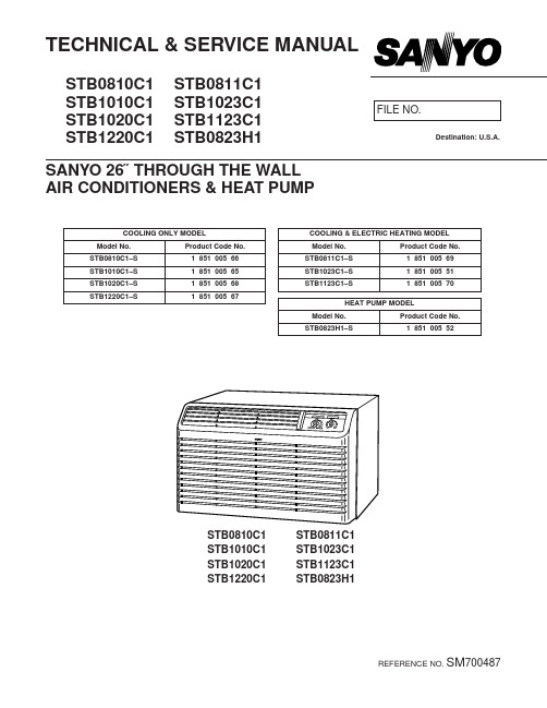
TECHNICAL & SERVICE MANUALSTB0810C1STB0811C1STB1010C1STB1023C1STB1020C1STB1123C1STB1220C1STB0823H1SANYO 26˝ THROUGH THE WALL AIR CONDITIONERS & HEAT PUMPSTB0810C1 STB0811C1STB1010C1 STB1023C1STB1020C1 STB1123C1STB1220C1 STB0823H1Destination: U.S.A.HOW TO USE THIS MANUALThis manual is designed to help service personnel to understand basic functions, operation and possible troubles and their remedies on SANYO 26˝ Through The Wall Air Conditioner. You can use this manual both as a reference to find specific information about the capacity, construction of the unit, and as a source of information to help you set up and maintain the air conditioner. Please use this manual to make your work easier, keep the air conditioner functioning well, and keep your customer satisfied.Please read IMPORTANT ! precautional information on the previous page before you start actual work.SANYO 26˝ THROUGH THE WALL A/C MODEL IDENTIFICATIONSANYO 26˝ Through The Wall Air Conditioner is identified by a model number. Cooling or heating capacity, electrical information and special features included on the air conditioner are indicated on the model number.Table of ContentsPage 1.OPERATING RANGE (1)2.SPECIFICATIONS2-1.Unit Specifications (2)2-2.Major Component Specifications (4)2-3.Other Component Specifications (6)3.DIMENSIONAL DATA (7)4.REFRIGERANT FLOW DIAGRAM (8)5.PERFORMANCE DATA5-1.Cooling Capacity (9)5-2.Heating Capacity (17)6.ELECTRICAL DATA6-1.Electrical Characteristics (18)6-2.Electrical Wiring Diagrams (21)6-3.P.C.B.Ass'y (Printed Pattern) (27)7.TROUBLESHOOTING7-1.Check before and after troubleshooting (28)7-2.Air conditioner does not operate (29)7-3.Some part of air conditioner does not operate (31)7-4.Air conditioner operates, but abnormalities are observed (33)7-5.If a sensor is defective (34)8.CHECKING ELECTRICAL COMPONENTS8-1.Measurement of Insulation Resistance (35)8-2.Checking Motor Capacitor (36)8-3.Checking Fan Motor Winding (36)8-4.Checking Compressor Motor Winding (36)8-5.Checking Thermistor (36)9.DISASSEMBLY PROCEDURE9-1.Removing Front Grille (37)9-2.Removing Wall Sleeve (37)9-3.Removing Electrical Component Box (37)9-4.Removing Electric Heater (38)9-5.Removing Blower Wheel (39)9-6.Removing Evaporator (39)9-7.Removing Condenser (40)9-8.Removing Propeller Fan (40)9-9.Removing Fan Motor (41)10.FUNCTION10-1.Room temperature Control (42)10-2.Defrosting Operation (Heating) (45)1.OPERATING RANGEs COOLING ONLY MODELModels STB0810C1STB1010C1STB1020C1STB1220C1s COOLING & ELECTRIC HEATING MODELModels STB0811C1STB1023C1STB1123C1s HEAT PUMP MODELModel STB0823H12.SPECIFICATIONS 2-1.Unit Specifications2-2.Major Component Specifications2-3.Other Component SpecificationsModels STB0810C1STB1010C1STB1020C1STB1220C1STB0811C1STB1023C1STB1123C1STB0823H1Room Thermostat YTB-2U136YTB-2U358 Model STB1020C1 STB0810C1STB0811C1 STB1023C1STB1220C1 STB1010C1 STB1123C1 Openrating temp.Cold°F ON: 65 / OFF: 61±3 (Diff: 4 Deg)Warm°F ON: 90 / OFF:86PTC Thermister (for compressor start up)PTH491A04AR470N500 Model STB0810C1 STB0811C1Resistance at 77°FΩ47±30%Relay (Heater)VC20A-115-S VC20A-230-S Model STB0811C1STB1023C1 STB1123C1 Coil rating AC115V , 60Hz AC208/230V , 60Hz Contact rating AC265V , 22A AC265V , 22AElectoric Heater Ass'y AH-H06S AH-H10S Model STB0811C1STB1023C1 STB0823H1STB1123C1 Heater Element Rating 1.22 kW , 115V 3.4 kW , 230VResistanceΩ 9.5±1.5% (at 68°F)13.6±1.5% (at 68°F)Watt Dinsty w/in28.913.2Dimension In Dia 3/8 , Leng 36Dia 3/8 , Leng 36 Heater Thermo.Type CS-7LOpenrating temp°F OFF : 122±5 / ON : 95±9 Fuse Type SF-152UOpenrating temp°F306±5Power Trnsformer ATR-J64ULN2Model STB0823H1Rating Primary AC220V , 60HzSecondary AC19V , 0.3AThermister (Room sensor)PBC-41E-S29Model STB0823H1Resistance at 32°F kΩ15±5%Thermister (Outdoor coil)PBC-41E-S14Model STB0823H1Resistance at 32°F kΩ15±5%4-way Valve (Solenoid coil)CHV-01AQ503UA1(Coil) / CHV-01U1(Valve) Model STB0823H1Coil raiting AC208/230V (60Hz) , 6W3.DIMENSIONAL DATAModels STB0810C1STB1010C1STB1020C1STB1220C1 STB0811C1STB1023C1STB1123C1STB0823H14.REFRIGERANT FLOW DIAGRAM Models STB0810C1STB1010C1STB1020C1STB1220C1 STB0811C1STB1023C1STB1123C1Model STB0823H15.PERFORMANCE DATA5-1.Cooling CapacityModel STB0810C1115 V Single phase 60 HzRATING CAPACITY8,200BTU/hAIR FLOW RATE270CFMEVAPORATOR CONDENSERENT. TEMP. °F (°C)OUTDOOR AMBIENT TEMP. °F( °C)W.B. D.B. 67 75 85 95 105 110(19.4) (23.9) (29.4) (35.0) (40.6) (43.3)TC8,2607,9007,5407,1806,7506,210CM0.600.650.700.750.790.8470 (21.1)SHC6,2606,1005,9405,7805,5805,3505973 (22.8)SHC7,3107,1506,9906,8306,6306,210(15.0)77 (25.0)SHC8,2607,9007,5407,1806,7506,21080 (26.7)SHC8,2607,9007,5407,1806,7506,21084 (28.9)SHC8,2607,9007,5407,1806,7506,21088 (31.1)SHC8,2607,9007,5407,1806,7506,210TC9,3508,4808,0907,7107,2506,670CM0.620.670.720.770.810.8670 (21.1)SHC5,1705,0104,8404,6804,4904,2606373 (22.8)SHC6,2206,0605,8905,7305,5405,310(17.2)77 (25.0)SHC7,2707,1106,9406,7806,5906,36080 (26.7)SHC8,3208,1607,9907,7107,2506,67084 (28.9)SHC8,8608,4808,0907,7107,2506,67088 (31.1)SHC8,8608,4808,0907,7107,2506,670TC9,4309,0208,610#8,2007,7107,090CM0.640.690.740.790.840.8970 (21.1)SHC4,0503,8903,7303,5703,3803,1506773 (22.8)SHC5,1004,9404,7804,6204,4304,200(19.4)77 (25.0)SHC6,1505,9905,8305,6705,4805,25080 (26.7)SHC7,2007,0406,8706,7206,5306,29084 (28.9)SHC8,2508,0907,9207,7707,5807,09088 (31.1)SHC9,3009,0208,6108,2007,7107,090TC10,0009,5609,1308,6908,1707,520CM0.660.710.760.820.860.9173 (22.8)SHC3,9703,8203,6603,5003,3203,0907077 (25.0)SHC5,0204,8604,7104,5504,3704,140(21.1)80 (26.7)SHC6,0705,9105,7605,6005,4205,19084 (28.9)SHC7,1206,9606,8106,6506,4706,24088 (31.1)SHC8,1708,0107,8607,7007,5207,290TC10,61010,1509,6709,1308,5407,950CM0.670.730.780.840.890.94 7377 (25.0)SHC3,8503,6903,5303,3603,1702,970(22.8)80 (26.7)SHC4,9004,7404,5804,4004,2204,02084 (28.9)SHC5,9505,7905,6305,4505,2605,07088 (31.1)SHC7,0006,8406,6806,5006,3106,120TC :Total Cooling Capacity (BTU/h)SHC :Sensible Heat Capacity (BTU/h)CM :Compressor Input (kW)Rating conditions (#Mark) areOutdoor Ambient Temp. 95°F (35°C) D.B.Model STB1010C1115 V Single phase 60 HzRATING CAPACITY10,200BTU/hAIR FLOW RATE270CFMEVAPORATOR CONDENSERENT. TEMP. °F (°C)OUTDOOR AMBIENT TEMP. °F( °C)W.B. D.B. 67 75 85 95 105 110(19.4) (23.9) (29.4) (35.0) (40.6) (43.3)TC10,2809,8309,3808,9408,3907,730CM0.800.870.93 1.00 1.06 1.1370 (21.1)SHC7,2207,0006,7906,5806,3206,0205973 (22.8)SHC8,2708,0507,8407,6307,3707,070(15.0)77 (25.0)SHC9,3209,1008,8908,6808,3907,73080 (26.7)SHC10,2809,8309,3808,9408,3907,73084 (28.9)SHC10,2809,8309,3808,9408,3907,73088 (31.1)SHC10,2809,8309,3808,9408,3907,730TC11,63010,55010,0709,5909,0108,290CM0.820.890.95 1.02 1.09 1.1570 (21.1)SHC6,1305,9105,7005,4905,2404,9306373 (22.8)SHC7,1806,9606,7506,5406,2905,980(17.2)77 (25.0)SHC8,2308,0107,8007,5807,3307,03080 (26.7)SHC9,2809,0608,8508,6308,3808,08084 (28.9)SHC10,33010,1109,9009,5909,0108,29088 (31.1)SHC11,03010,55010,0709,5909,0108,290TC11,73011,22010,710#10,2009,5908,820CM0.850.920.98 1.05 1.12 1.1970 (21.1)SHC5,0004,7804,5704,3604,1103,8106773 (22.8)SHC6,0505,8305,6205,4105,1604,860(19.4)77 (25.0)SHC7,0906,8806,6706,4606,2105,91080 (26.7)SHC8,1407,9307,7207,5107,2606,96084 (28.9)SHC9,1908,9808,7708,5608,3108,01088 (31.1)SHC10,24010,0309,8209,6109,3608,820TC12,43011,89011,35010,81010,1609,350CM0.870.94 1.01 1.08 1.15 1.2273 (22.8)SHC4,9004,6904,4804,2804,0403,7407077 (25.0)SHC5,9505,7405,5305,3305,0904,790(21.1)80 (26.7)SHC7,0006,7906,5806,3806,1405,84084 (28.9)SHC8,0507,8407,6307,4307,1906,89088 (31.1)SHC9,1008,8908,6808,4808,2407,940TC13,19012,62012,03011,35010,6309,880CM0.890.97 1.04 1.11 1.18 1.26 7377 (25.0)SHC4,7604,5504,3404,1003,8603,610(22.8)80 (26.7)SHC5,8105,6005,3905,1504,9004,65084 (28.9)SHC6,8506,6506,4406,2005,9505,70088 (31.1)SHC7,9007,7007,4907,2507,0006,750TC :Total Cooling Capacity (BTU/h)SHC :Sensible Heat Capacity (BTU/h)CM :Compressor Input (kW)Rating conditions (#Mark) areOutdoor Ambient Temp. 95°F (35°C) D.B.Model STB1020C1230 V Single phase 60 HzRATING CAPACITY9,700BTU/hAIR FLOW RATE270CFMEVAPORATOR CONDENSERENT. TEMP. °F (°C)OUTDOOR AMBIENT TEMP. °F( °C)W.B. D.B. 67 75 85 95 105 110(19.4) (23.9) (29.4) (35.0) (40.6) (43.3)TC9,7709,3508,9208,5007,9807,350CM0.760.820.880.940.97 1.0070 (21.1)SHC6,9806,7806,5806,3806,1405,8605973 (22.8)SHC8,0307,8307,6307,4307,1906,910(15.0)77 (25.0)SHC9,0808,8808,6808,4807,9807,35080 (26.7)SHC9,7709,3508,9208,5007,9807,35084 (28.9)SHC9,7709,3508,9208,5007,9807,35088 (31.1)SHC9,7709,3508,9208,5007,9807,350TC11,06010,0309,5709,1208,5707,890CM0.780.840.900.97 1.00 1.0270 (21.1)SHC5,8905,6905,4905,2905,0504,7606373 (22.8)SHC6,9406,7406,5406,3406,1005,810(17.2)77 (25.0)SHC7,9907,7907,5807,3907,1506,86080 (26.7)SHC9,0408,8408,6308,4408,2007,89084 (28.9)SHC10,0909,8909,5709,1208,5707,89088 (31.1)SHC10,49010,0309,5709,1208,5707,890TC11,15010,67010,180#9,7009,1208,390CM0.800.870.93 1.00 1.03 1.0670 (21.1)SHC4,7604,5604,3604,1603,9303,6506773 (22.8)SHC5,8105,6105,4105,2104,9804,700(19.4)77 (25.0)SHC6,8606,6606,4606,2606,0305,75080 (26.7)SHC7,9107,7107,5107,3107,0806,80084 (28.9)SHC8,9608,7608,5608,3608,1307,85088 (31.1)SHC10,0109,8109,6109,4109,1208,390TC11,82011,31010,80010,2809,6708,890CM0.830.890.96 1.03 1.06 1.0973 (22.8)SHC4,6704,4704,2804,0903,8603,5807077 (25.0)SHC5,7205,5205,3305,1404,9104,630(21.1)80 (26.7)SHC6,7706,5706,3806,1905,9605,68084 (28.9)SHC7,8207,6207,4307,2407,0106,73088 (31.1)SHC8,8708,6708,4808,2908,0607,780TC12,55012,00011,44010,80010,1109,400CM0.840.920.98 1.05 1.09 1.12 7377 (25.0)SHC4,5304,3404,1403,9203,6903,450(22.8)80 (26.7)SHC5,5805,3905,1904,9704,7404,50084 (28.9)SHC6,6306,4406,2406,0205,7905,55088 (31.1)SHC7,6807,4907,2907,0706,8406,600TC :Total Cooling Capacity (BTU/h)SHC :Sensible Heat Capacity (BTU/h)CM :Compressor Input (kW)Rating conditions (#Mark) areOutdoor Ambient Temp. 95°F (35°C) D.B.Model STB1220C1230 V Single phase 60 HzRATING CAPACITY11,500BTU/hAIR FLOW RATE270CFMEVAPORATOR CONDENSERENT. TEMP. °F (°C)OUTDOOR AMBIENT TEMP. °F( °C)W.B. D.B. 67 75 85 95 105 110(19.4) (23.9) (29.4) (35.0) (40.6) (43.3)TC11,59011,08010,58010,0709,4608,710CM0.920.99 1.06 1.14 1.21 1.2870 (21.1)SHC7,8807,6207,3707,1306,8306,4805973 (22.8)SHC8,9308,6708,4208,1807,8807,530(15.0)77 (25.0)SHC9,9809,7209,4709,2308,9308,58080 (26.7)SHC11,03010,77010,52010,0709,4608,71084 (28.9)SHC11,59011,08010,58010,0709,4608,71088 (31.1)SHC11,59011,08010,58010,0709,4608,710TC13,11011,89011,35010,81010,1609,350CM0.94 1.02 1.09 1.17 1.24 1.3170 (21.1)SHC6,7906,5306,2806,0405,7405,3906373 (22.8)SHC7,8407,5807,3307,0906,7906,440(17.2)77 (25.0)SHC8,8908,6308,3808,1407,8407,49080 (26.7)SHC9,9409,6809,4309,1908,8908,54084 (28.9)SHC10,99010,73010,48010,2309,9409,35088 (31.1)SHC12,04011,78011,35010,81010,1609,350TC13,22012,65012,070#11,50010,8109,950CM0.97 1.05 1.13 1.21 1.28 1.3570 (21.1)SHC5,6505,4005,1504,9004,6204,2606773 (22.8)SHC6,7006,4506,2005,9505,6705,310(19.4)77 (25.0)SHC7,7507,5007,2507,0006,7206,36080 (26.7)SHC8,8008,5508,3008,0507,7707,41084 (28.9)SHC9,8509,6009,3509,1008,8108,46088 (31.1)SHC10,90010,65010,40010,1509,8609,510TC14,02013,41012,80012,19011,46010,540CM 1.00 1.08 1.16 1.24 1.32 1.3973 (22.8)SHC5,5505,3005,0504,8104,5304,1907077 (25.0)SHC6,6006,3506,1005,8605,5805,230(21.1)80 (26.7)SHC7,6507,4007,1506,9106,6306,28084 (28.9)SHC8,7008,4508,2007,9607,6807,33088 (31.1)SHC9,7509,5009,2509,0108,7308,380TC14,88014,23013,56012,80011,98011,140CM 1.02 1.11 1.19 1.27 1.35 1.43 7377 (25.0)SHC5,3805,1404,8904,6204,3304,040(22.8)80 (26.7)SHC6,4306,1905,9405,6705,3805,09084 (28.9)SHC7,4807,2406,9906,7206,4306,14088 (31.1)SHC8,5308,2908,0407,7707,4807,190TC :Total Cooling Capacity (BTU/h)SHC :Sensible Heat Capacity (BTU/h)CM :Compressor Input (kW)Rating conditions (#Mark) areOutdoor Ambient Temp. 95°F (35°C) D.B.Model STB0811C1115 V Single phase 60 HzRATING CAPACITY8,000BTU/hAIR FLOW RATE250CFMEVAPORATOR CONDENSERENT. TEMP. °F (°C)OUTDOOR AMBIENT TEMP. °F( °C)W.B. D.B. 67 75 85 95 105 110(19.4) (23.9) (29.4) (35.0) (40.6) (43.3)TC8,0607,7107,3607,0106,5806,060CM0.590.640.680.730.790.8570 (21.1)SHC5,9705,8105,6505,4905,3005,0705973 (22.8)SHC6,9406,7806,6206,4606,2706,040(15.0)77 (25.0)SHC7,9107,7107,3607,0106,5806,06080 (26.7)SHC8,0607,7107,3607,0106,5806,06084 (28.9)SHC8,0607,7107,3607,0106,5806,06088 (31.1)SHC8,0607,7107,3607,0106,5806,060TC9,1208,2707,9007,5207,0706,500CM0.610.650.700.750.810.8770 (21.1)SHC4,9604,8004,6304,4704,2904,0506373 (22.8)SHC5,9305,7705,6105,4505,2605,030(17.2)77 (25.0)SHC6,9006,7406,5806,4206,2306,00080 (26.7)SHC7,8707,7107,5507,3907,0706,50084 (28.9)SHC8,6508,2707,9007,5207,0706,50088 (31.1)SHC8,6508,2707,9007,5207,0706,500TC9,2008,8008,400#8,0007,5206,920CM0.620.670.720.770.840.9070 (21.1)SHC3,9203,7503,6003,4403,2503,0206773 (22.8)SHC4,8904,7304,5704,4104,2203,990(19.4)77 (25.0)SHC5,8605,7005,5405,3805,2004,97080 (26.7)SHC6,8306,6706,5106,3506,1705,94084 (28.9)SHC7,8007,6407,4807,3307,1406,91088 (31.1)SHC8,7808,6108,4008,0007,5206,920TC9,7509,3308,9008,4807,9707,340CM0.640.690.740.800.860.9273 (22.8)SHC3,8403,6803,5303,3703,1902,9707077 (25.0)SHC4,8104,6604,5004,3504,1603,940(21.1)80 (26.7)SHC5,7905,6305,4705,3205,1304,91084 (28.9)SHC6,7606,6006,4406,2906,1105,88088 (31.1)SHC7,7307,5707,4207,2607,0806,850TC10,3509,9009,4308,9008,3407,750CM0.650.710.760.820.880.95 7377 (25.0)SHC3,7203,5703,4103,2303,0402,860(22.8)80 (26.7)SHC4,6904,5404,3804,2004,0203,83084 (28.9)SHC5,6605,5105,3505,1804,9904,80088 (31.1)SHC6,6406,4806,3206,1505,9605,770TC :Total Cooling Capacity (BTU/h)SHC :Sensible Heat Capacity (BTU/h)CM :Compressor Input (kW)Rating conditions (#Mark) areOutdoor Ambient Temp. 95°F (35°C) D.B.Model STB1023C1230 V Single phase 60 HzRATING CAPACITY9,500BTU/hAIR FLOW RATE250CFMEVAPORATOR CONDENSERENT. TEMP. °F (°C)OUTDOOR AMBIENT TEMP. °F( °C)W.B. D.B. 67 75 85 95 105 110(19.4) (23.9) (29.4) (35.0) (40.6) (43.3)TC9,5709,1608,7408,3207,8207,200CM0.740.800.860.920.96 1.0170 (21.1)SHC6,7006,5006,3006,1005,8605,5805973 (22.8)SHC7,6707,4707,2707,0706,8406,550(15.0)77 (25.0)SHC8,6408,4408,2408,0407,8107,20080 (26.7)SHC9,5709,1608,7408,3207,8207,20084 (28.9)SHC9,5709,1608,7408,3207,8207,20088 (31.1)SHC9,5709,1608,7408,3207,8207,200TC10,8309,8209,3808,9308,3907,720CM0.760.830.880.950.99 1.0370 (21.1)SHC5,6905,4905,2905,0904,8504,5706373 (22.8)SHC6,6606,4606,2606,0605,8305,540(17.2)77 (25.0)SHC7,6307,4307,2307,0306,8006,51080 (26.7)SHC8,6008,4008,2008,0007,7707,48084 (28.9)SHC9,5809,3709,1708,9308,3907,72088 (31.1)SHC10,2709,8209,3808,9308,3907,720TC10,93010,4509,980#9,5008,9308,220CM0.790.850.910.98 1.02 1.0770 (21.1)SHC4,6404,4404,2404,0403,8103,5306773 (22.8)SHC5,6105,4105,2105,0204,7904,500(19.4)77 (25.0)SHC6,5806,3806,1805,9905,7605,47080 (26.7)SHC7,5507,3507,1506,9606,7306,45084 (28.9)SHC8,5308,3208,1307,9307,7007,42088 (31.1)SHC9,5009,3009,1008,9008,6708,220TC11,58011,08010,57010,0709,4708,710CM0.810.870.94 1.01 1.05 1.1073 (22.8)SHC4,5504,3504,1603,9703,7403,4607077 (25.0)SHC5,5205,3305,1304,9404,7104,440(21.1)80 (26.7)SHC6,5006,3006,1005,9105,6905,41084 (28.9)SHC7,4707,2707,0806,8806,6606,38088 (31.1)SHC8,4408,2408,0507,8607,6307,350TC12,29011,76011,20010,5709,9009,210CM0.830.900.96 1.03 1.08 1.13 7377 (25.0)SHC4,4104,2204,0203,8003,5703,340(22.8)80 (26.7)SHC5,3805,1905,0004,7804,5404,31084 (28.9)SHC6,3606,1605,9705,7505,5205,28088 (31.1)SHC7,3307,1406,9406,7206,4906,250TC :Total Cooling Capacity (BTU/h)SHC :Sensible Heat Capacity (BTU/h)CM :Compressor Input (kW)Rating conditions (#Mark) areOutdoor Ambient Temp. 95°F (35°C) D.B.Model STB1123C1230 V Single phase 60 HzRATING CAPACITY11,300BTU/hAIR FLOW RATE250CFMEVAPORATOR CONDENSERENT. TEMP. °F (°C)OUTDOOR AMBIENT TEMP. °F( °C)W.B. D.B. 67 75 85 95 105 110(19.4) (23.9) (29.4) (35.0) (40.6) (43.3)TC11,38010,89010,4009,9009,3008,560CM0.900.98 1.04 1.12 1.19 1.2670 (21.1)SHC7,6107,3607,1106,8606,5706,2105973 (22.8)SHC8,5908,3308,0807,8307,5407,180(15.0)77 (25.0)SHC9,5609,3009,0508,8008,5108,16080 (26.7)SHC10,53010,28010,0209,7809,3008,56084 (28.9)SHC11,38010,89010,4009,9009,3008,56088 (31.1)SHC11,38010,89010,4009,9009,3008,560TC12,89011,68011,15010,6209,9809,190CM0.93 1.00 1.07 1.15 1.22 1.2970 (21.1)SHC6,6106,3506,1005,8505,5605,2006373 (22.8)SHC7,5807,3207,0706,8206,5306,170(17.2)77 (25.0)SHC8,5508,2908,0407,7907,5007,15080 (26.7)SHC9,5209,2709,0108,7708,4708,12084 (28.9)SHC10,49010,2409,9909,7409,4509,09088 (31.1)SHC11,47011,21010,96010,6209,9809,190TC13,00012,43011,870#11,30010,6209,770CM0.96 1.03 1.11 1.19 1.26 1.3370 (21.1)SHC5,5505,2905,0404,8004,5104,1606773 (22.8)SHC6,5206,2606,0205,7705,4805,130(19.4)77 (25.0)SHC7,4907,2406,9906,7406,4506,10080 (26.7)SHC8,4608,2107,9607,7107,4307,07084 (28.9)SHC9,4309,1808,9308,6908,4008,04088 (31.1)SHC10,41010,1509,9009,6609,3709,020TC13,77013,18012,58011,98011,26010,360CM0.98 1.06 1.14 1.22 1.30 1.3773 (22.8)SHC5,4505,2004,9504,7104,4304,0807077 (25.0)SHC6,4206,1705,9205,6805,4005,050(21.1)80 (26.7)SHC7,3907,1406,8906,6506,3706,02084 (28.9)SHC8,3608,1107,8707,6307,3406,99088 (31.1)SHC9,3309,0808,8408,6008,3107,970TC14,62013,98013,32012,58011,77010,950CM 1.00 1.09 1.17 1.25 1.33 1.41 7377 (25.0)SHC5,2905,0404,7904,5204,2303,940(22.8)80 (26.7)SHC6,2606,0205,7705,4905,2004,91084 (28.9)SHC7,2306,9906,7406,4606,1705,88088 (31.1)SHC8,2007,9607,7107,4307,1406,850TC :Total Cooling Capacity (BTU/h)SHC :Sensible Heat Capacity (BTU/h)CM :Compressor Input (kW)Rating conditions (#Mark) areOutdoor Ambient Temp. 95°F (35°C) D.B.Model STB0823H1230 V Single phase 60 HzRATING CAPACITY8,000BTU/hAIR FLOW RATE250CFMEVAPORATOR CONDENSERENT. TEMP. °F (°C)OUTDOOR AMBIENT TEMP. °F( °C)W.B. D.B. 67 75 85 95 105 110(19.4) (23.9) (29.4) (35.0) (40.6) (43.3)TC8,0607,7107,3607,0106,5806,060CM0.610.660.700.750.800.8570 (21.1)SHC5,9805,8105,6505,4905,3005,0705973 (22.8)SHC6,9506,7906,6306,4706,2706,040(15.0)77 (25.0)SHC7,9207,7107,3607,0106,5806,06080 (26.7)SHC8,0607,7107,3607,0106,5806,06084 (28.9)SHC8,0607,7107,3607,0106,5806,06088 (31.1)SHC8,0607,7107,3607,0106,5806,060TC9,1208,2707,9007,5207,0706,500CM0.620.670.720.770.820.8770 (21.1)SHC4,9604,8004,6404,4804,2904,0606373 (22.8)SHC5,9405,7705,6105,4505,2605,030(17.2)77 (25.0)SHC6,9106,7506,5806,4306,2406,00080 (26.7)SHC7,8807,7207,5607,4007,0706,50084 (28.9)SHC8,6508,2707,9007,5207,0706,50088 (31.1)SHC8,6508,2707,9007,5207,0706,500TC9,2008,8008,400#8,0007,5206,920CM0.640.690.740.800.850.9070 (21.1)SHC3,9203,7603,6003,4503,2603,0306773 (22.8)SHC4,8904,7304,5704,4204,2304,000(19.4)77 (25.0)SHC5,8705,7005,5505,3905,2004,97080 (26.7)SHC6,8406,6806,5206,3606,1705,95084 (28.9)SHC7,8107,6507,4907,3307,1506,92088 (31.1)SHC8,7808,6208,4008,0007,5206,920TC9,7509,3308,9008,4807,9707,340CM0.660.710.760.820.870.9273 (22.8)SHC3,8503,6903,5303,3803,2002,9707077 (25.0)SHC4,8204,6604,5104,3504,1703,950(21.1)80 (26.7)SHC5,7905,6305,4805,3205,1404,92084 (28.9)SHC6,7606,6106,4506,3006,1105,89088 (31.1)SHC7,7407,5807,4207,2707,0906,860TC10,3509,9009,4308,9008,3407,750CM0.670.730.780.840.900.95 7377 (25.0)SHC3,7303,5703,4103,2403,0502,860(22.8)80 (26.7)SHC4,7004,5504,3904,2104,0203,83084 (28.9)SHC5,6705,5205,3605,1805,0004,81088 (31.1)SHC6,6406,4906,3306,1505,9705,780TC :Total Cooling Capacity (BTU/h)SHC :Sensible Heat Capacity (BTU/h)CM :Compressor Input (kW)Rating conditions (#Mark) areOutdoor Ambient Temp. 95°F (35°C) D.B.5-2.Heating Capacity (Heat pump Performance)6.ELECTRICAL DATA6-1.Electrical CharacteristicsModel STB0810C1Outdoor Unit Complete UnitFan Motor CompressorPerformance at115V 1-phase 60HzRating Conditions Running Amps.A 1.267.048.3Power Input kW0.1450.7950.94 Full Load Conditions Running Amps.A 1.268.349.6Power Input kW0.1450.935 1.08Model STB1010C1Outdoor Unit Complete UnitFan Motor CompressorPerformance at115V 1-phase 60HzRating Conditions Running Amps.A 1.269.3410.6Power Input kW0.145 1.055 1.20 Full Load Conditions Running Amps.A 1.2611.0412.3Power Input kW0.145 1.255 1.40Model STB1020C1Outdoor Unit Complete UnitFan Motor CompressorPerformance at230 / 208V 1-phase 60HzRating Conditions Running Amps.A0.61/0.64 4.39/ 4.66 5.0/ 5.3Power Input kW0.142/0.1320.998/0.978 1.14/ 1.11 Full Load Conditions Running Amps.A0.61/0.64 4.99/ 5.26 5.6/ 5.9Power Input kW0.142/0.132 1.118/ 1.098 1.26/ 1.23Model STB1220C1Outdoor Unit Complete UnitFan Motor CompressorPerformance at230 / 208V 1-phase 60HzRating Conditions Running Amps.A0.61/0.64 5.49/ 5.96 6.1/ 6.6Power Input kW0.142/0.132 1.208/ 1.198 1.35/ 1.33 Full Load Conditions Running Amps.A0.61/0.64 6.29/ 6.96 6.9/7.6Power Input kW0.142/0.132 1.428/ 1.438 1.57/ 1.57Rating Conditions: Indoor Air Temperature 80°F (26.7°C) D.B. / 67°F (19.4°C) W.B.Outdoor Air Temperature 95°F (35°C) D.B.Full Load Conditions: Indoor Air Temperature 90°F (32.2°C) D.B. / 73°F (22.8°C) W.B.Outdoor Air Temperature 110°F (43.3°C) D.B.Model STB0811C1Outdoor Unit Complete UnitFan Motor CompressorPerformance at115V 1-phase 60HzRating Conditions Running Amps.A 1.267.048.3Power Input kW0.1450.7750.92 Full Load Conditions Running Amps.A 1.268.349.6Power Input kW0.1450.945 1.09Model STB1023C1Outdoor Unit Complete UnitFan Motor CompressorPerformance at230 / 208V 1-phase 60HzRating Conditions Running Amps.A0.61/0.64 4.39/ 4.66 5.0/ 5.3Power Input kW0.142/0.1320.978/0.958 1.12/ 1.09 Full Load Conditions Running Amps.A0.61/0.64 4.99/ 5.26 5.6/ 5.9Power Input kW0.142/0.132 1.128/ 1.088 1.27/ 1.22Model STB1123C1Outdoor Unit Complete UnitFan Motor CompressorPerformance at230 / 208V 1-phase 60HzRating Conditions Running Amps.A0.61/0.64 5.39/ 5.86 6.0/ 6.5Power Input kW0.142/0.132 1.188/ 1.178 1.33/ 1.31 Full Load Conditions Running Amps.A0.61/0.64 6.29/ 6.86 6.9/7.5Power Input kW0.142/0.132 1.408/ 1.408 1.55/ 1.54Rating Conditions: Indoor Air Temperature 80°F (26.7°C) D.B. / 67°F (19.4°C) W.B.Outdoor Air Temperature 95°F (35°C) D.B.Full Load Conditions: Indoor Air Temperature 90°F (32.2°C) D.B. / 73°F (22.8°C) W.B.Outdoor Air Temperature 110°F (43.3°C) D.B.Model STB0823H1COOLINGOutdoor Unit Complete UnitFan Motor CompressorPerformance at230 / 208V 1-phase 60HzRating Conditions Running Amps.A0.61/0.64 3.59/ 3.86 4.2/ 4.5Power Input kW0.142/0.1320.798/0.7880.94/0.92 Full Load Conditions Running Amps.A0.61/0.64 4.29/ 4.46 4.9/ 5.1Power Input kW0.142/0.1320.948/0.918 1.09/ 1.05Rating Conditions: Indoor Air Temperature 80°F (26.7°C) D.B. / 67°F (19.4°C) W.B.Outdoor Air Temperature 95°F (35°C) D.B.Full Load Conditions: Indoor Air Temperature 90°F (32.2°C) D.B. / 73°F (22.8°C) W.B.Outdoor Air Temperature 110°F (43.3°C) D.B.HEATINGOutdoor Unit Complete UnitFan Motor CompressorPerformance at230 / 208V 1-phase 60HzRating Conditions Running Amps.A0.61/0.64 3.39/ 3.66 4.0/ 4.3Power Input kW0.142/0.1320.738/0.7380.88/0.87 Full Load Conditions Running Amps.A0.61/0.64 4.09/ 4.51 4.7/ 5.2Power Input kW0.142/0.1320.898/0.888 1.04/ 1.02Rating Conditions: Indoor Air Temperature 70°F (21.1°C) D.B.Outdoor Air Temperature 47°F (8.3°C) D.B. / 43°F (6.1°C) W.B.Full Load Conditions: Indoor Air Temperature 80°F (26.7°C) D.B.Outdoor Air Temperature 75°F (23.9°C) D.B. / 65°F (18.3°C) W.B.6-2.Electrical Wiring DiagramsModelsSTB0810C1STB1010C1LAYOUT FOR ELECTRIC PARTSModel STB0823H1Model STB0823H1Capacitor (FM)VaristorCapacitor (CM)Power transformer Power pack control PCB Thermistor room temp.Main control switch Control switch temp.settingLAYOUT FOR ELECTRIC PARTSBEFORE OPENING THE BOXFan switchLidPower cordAFTER OPENING THE BOX6-3.P.C.B. Ass'y (Printed Pattern) POW–STBH (For model STB0823H1)7.TROUBLESHOOTING7-1.Check before and after troubleshooting7-1-1.Check power supply.q Check that voltage is in specified range (±10% of the rating).q Check that power is being supplied.7-1-2.Check lead wires and connectors.q Check that coating of lead wires is not damaged.q Check that lead wires and connectors are firmly connected.q Check that wiring is correct.7-2.Air conditioner does not operate.7-2-1.Circuit breaker trips (or fuse blows).A. When the circuit breaker is set to ON, it is tripped soon. (Resetting is not possible.)q There is a possibility of ground fault.q Check insulation resistance.If resistance value is 2MΩor less, insulation is defective (“NO”).NOTE1.If any poorly insulated part is found, exclude that part from circuit with other parts properly connected, and thenmeasure insulation resistance of entire air conditioner again to locate defective part.2.Replace defective part with new one.B. Circuit breaker trips in several minutes after turning the air conditioner on. q There is a possibility of short circuit.7-2-2.Neither fan motor nor compressor motor runs.A. Power is not supplied.B. Check "MODE selector" on the control panel.C. Check transformer.(Only for heat pump model)7-3.Some part of air conditioner does not operate. 7-3-1.Only fan does not run.7-3-2.Electric heater does not work.7-3-3.Only compressor unit does not run.A. Check setting temperature.B. Check compressor and electrical parts.NOT restart it immediately, as this7-4.Air conditioner operates, but abnormalities are observed. 7-4-1.Operation does not switch from HEAT to COOL (or COOL to HEAT).7-4-3.Excessive cooling or heating.。
三洋1.2HP冷暖空调split system heat pump n4h4维修手册说明书

MODELS
N4H418*KB300 N4H419*KB100 N4H424*KB300 N4H430*KB300 N4H436*KB300
N4H442*KB300 N4H448*KB300 N4H460*KB400 N4H461*KA100
* = A or G
! WARNING
DEATH, PERSONAL INJURY, AND/OR PROPERTY DAMAGE HAZARD
The information contained in this manual is intended for use by a qualified service technician familiar with safety procedures and equipped with the proper tools and test instruments.
R−410A CHARGING CHART
Rating Plate (required) Subcooling Temperature ° F (° C)
° F (° C) ° F (° C) ° F (° C) ° F (° C) F (° C) F (° C)
6
3
8
4
10
6
12
7
14
8
16
9
R−410A Required Liquid Line Temperature ° F (° C) 78 26 76 24 74 23 72 22 70 21 68 20 80 27 78 26 76 24 74 23 72 22 70 21 82 28 80 27 78 26 76 24 74 23 72 22 84 29 82 28 80 27 78 26 76 24 74 23 86 30 84 29 82 28 80 27 78 26 76 24 88 31 86 30 84 29 82 28 80 27 78 26 90 32 88 31 86 30 84 29 82 28 80 27 92 33 90 32 88 31 86 30 84 29 82 28 94 34 92 33 90 32 88 31 86 30 84 29 96 36 94 34 92 33 90 32 88 31 86 30 98 37 96 36 94 34 92 33 90 32 88 31 100 38 98 37 96 36 94 34 92 33 90 32 104 40 102 39 100 38 98 37 96 36 94 34 106 41 104 40 102 39 100 38 98 37 96 36 108 42 106 41 104 40 102 39 100 38 98 37 110 43 108 42 106 41 104 40 102 39 100 38 112 44 110 43 108 42 106 41 104 40 102 39 114 46 112 44 110 43 108 42 106 41 104 40 116 47 114 46 112 44 110 43 108 42 106 41 118 48 116 47 114 46 112 44 110 43 108 42 120 49 118 48 116 47 114 46 112 44 110 43 122 50 120 49 118 48 116 47 114 46 112 44 124 51 122 50 120 49 118 48 116 47 114 46
三洋LA4500 LA4500A LA4500B 2声道音频功放器中文版用户手册说明书

Monolithic Linear ICOrdering number:ENN1164CSANYO Electric Co.,Ltd. Semiconductor CompanyTOKYO OFFICE T okyo Bldg., 1-10, 1 Chome, Ueno, T aito-ku, TOKYO, 110-8534 JAPANPackage Dimensionsunit:mmFeatures• Low idling current (20mA/2 channels) enabling prolonged battery life.• Less dependence of idling current on V CC .• High power (5.3W typ. ×2).• High ripple rejection (60dB at steady state).Since filters are arranged in 3 stages (including 1 stage inside the IC) to attain satisfactory ripple rejection at tran-sient state, ripple occuring at the time of motor start can be prevented from mixing in.• Low pop noise at the time of power supply ON/OFF and good starting balance between both channels (0.6s.) due to built-in pop noise limiter.• Pins provided for compensating high frequency responce.• Low residual noise (0.4mV).• Wide supply voltage range (6 to 24V) fascilitating design of transformer power supply.• Built-in thermal shutdown circuit,• Designed so that inverse insertion or short between adja-cent pins causes no destruction.• Channel-to channel mirror image pin assignment and pro-vision of Pre GND, Power GND pins enabling stable op-eration and fascilitating artwork of printed circuit board.• Minimum number of external parts required (9pcs. min.,12pcs. typ.).• Audio muting capability (for automatic music selection,electronic tuner).SpecificationsAbsolute Maximum Ratings at Ta = 25˚C˚C ˚Cre t e m a r a P l o b m y S sn o i t i d n o C sg n i t a R t i n U e g a t l o v y l p p u s m u m i x a M V C C xa m 42V t n e r r u c t u p t u o m u m i x a M I O ka e p le n n a h c 15.2A n o i t a p i s s i d r e w o p e l b a w o l l A x a m d P kn i s t a e h e t i n i f n i h t i W 51We r u t a r e p m e t g n i t a r e p O r p o T 57+o t 02–er u t a r e p m e t e g a r o t S gt s T 051+o t 04–Sample Application Circuit 1Description of External PartsC1 (C1)Feedback capacitorsRelated to low roll-off frequency f L for –3dB (100µF, f L=60Hz).A capacitance value of 47µF to 100µF is recommended. Increasing the capacitance value makes thestarting time (t s) later. Decreasing the capacitance value makes the starting time (t s) earlier.C3 (C4)Bootstrap capacitorsDecreasing the capacitance value lowers output at low frequencies. A capacitance value of 47µF to100µF is recommended.C5 (C6)Oscillation blocking capacitorsPolyester film capacitor, being excellent in temperature characteristic, frequency characteristics, isrecommended.C7 (C8)Output capacitorsRelated to low roll-off frequency and output at low frequencies. BTL applications normally requireoutput capacitors.C9 (C10)Switching distortion compensating capacitorsCompensates switching distortion which occurs at a high frequency of 10kHz. Ceramic capacitor of0.01µF is recommended. If no problem arises in terms of radio-casette recorder design or tone, it isunnecessary to use these capacitors.C11Filter capacitor (A)Ripple filter circuit provided in power supply line. A capacitance value of 220µF is recommended.Ripple rejection SVRR starts to be saturated at 47µF. The starting time and pop noise generated at thetime of power supply ON must be considered when fixing the capacitance value. A capacitance value of100µF to 220µF is usable.C12Filter capacitor (B)Ripple filter circuit provided in bias circuit. A capacitance value of 100µF is recommended. 3V sufficesthe breakdown voltage of this capacitor. This capacitor is for ripple rejection at transient state and rejectsnoise “buzz” generated when the above-mentioned filter circuit provided in power supply line is satu-rated due to large ripple and supply voltage drop induced at the time of start of the motor connected topower supply line. If the motor is satisfactory in performance and the power supply regulation includingripple is 500mVrms or less, it is unnecessary to use this capacitor. If noise “buzz” is not offensive to theear, it is unnecessary to use this capacitor. In this case, other basic performances are not affected ad-versely.Feaures of IC Contents and Functions of Other Pins(a)Since the input circuit uses PNP transistors and the bias voltage is set nearly equal to 0, no input couplingcapacitor is required, thereby enabling direct coupling. However, if slider contact noise of the variable resistor presents any problem, connect a capacitor in series with input.(b)Various ideas embodied in the idling circuit enable reduced I CCO and prolonged battery life. Since the non-operating level of the idling circuit is made equal to that of the amplifier, crossover distortion does not worsen at the time of reduced voltage.(c)The open loop voltage gain is lowered and the negative feedback amount is made small to assure stable opera-tion. Radiation to the radio-frequency stage is made less by soft clipping.(d)Capacitors for oscillation compensation are contained as a means of reducing the number of external parts.10pF×2 and 2pF×2 are used. Hig roll-off frequency f H (–3dB point) depends on these capacitance values.(f H=28kHz)(e)A thermal shutdown (THD) circuit is contained to prevent the IC from being destroyed by abromal heat genera-tion attributable to insufficient heat dissipation. Pin (11) is used as THD control pin. Biasing pin (11) externally makes the operating temperature lower ; and connecting a resister across pin (11) and (10) makes the operating temperature higher. If pin (11) is connected to GND, the thermal shutdown circuit stops operating.(f)The pin assignment is carefully considered so that no destruction takes place even if power supply is applied at astate where adjacent pins are shorted by solder bridge, etc. Even 180°C-rotated insertion causes no destruction.(g)Collector pins (5), (16) and base pins (6), (15) for predrive can be conveniently used in applications. For oscilla-tion compensation occuring when operated at a lowered gain, connect a capacitor across the pins (4) and (6) anda capacitor across pins (15) and (16). For fH compensation occuring when operated at a lowered gain, connect acapacitor across pins (4) and (6) and a capacitor across pins (17) and (15). Further soft clippling and prevention of waveform distortion at high frequencies are attained by connecting a series circuit of diode (DS442) andresistor (10kΩ) across pin (6) and GND and the same across pin (15) and GND.Continued on next page.Continued from preceding page.(h)Feedback resistance R NF is contained and the voltage gain is fixed at 50dB so that the variations in the voltagegain can be minimized. The gain can be lowered by connecting R NF externally.(i)Biasing pin (12) as shown below causes DC audio muting to be applied, thereby cutting off the IC. This makesattack time, recovery time, pop noise, etc. saticefactory.It is recommended that the following method be used to control the NF pin.It is recommended that the following method be used to control the NF pin.Sample Application Circuit 2Output power (reference value) corresponding to supply voltage and load resistance.me t s yS R L V9V21V51V81o e r e t S 8Ω6Ω4Ω3Ω2ΩW4.1W8.1W4.2W0.3W5.3W5.2W2.3W5.4W3.5–W0.4W0.5W9.6W8.7–W6.5W4.7W8.9––e g d i r B 8Ω6Ω4ΩW5.4W5.5W0.7W5.8W5.9–W31W51–W81––(THD=10%)。
三洋岛柜使用说明书

三洋岛柜使用说明书
按键操作
1、测控状态下按Set键3秒后,进入用户菜单,显示St,再次按下SET键后显示St的参数值,此时通过操作或键修改温度设置值。
2、在显示St时,按下键后,显示PO,按下Set健后显示00,此时可通过或键输入控制管理者菜单密码。
输入控制管理者菜单密码后按下Set键,显示PO,可通过或键选择St、Po、C1、C2…u1参数项。
选定菜单项后按SET键进入当前菜单项参数值设置,按或键调整参数值,再按SET键返回菜单选择。
3、在任意参数设置状态下,按键或30秒无按键操作则退出参数设置并自动保存当前参数值。
4、手动强制操作:测控状态下,按键持续3秒后,可在制冷、制冷、除霜/除霜延迟、除霜滴水之强制切换。
注:
St、Po、C1、C3、C4、C5、C6、d1、d4、d5、d6、d8、d10、d11、A9、A11按上表参数设置(产品上电时必须将测试参数设置好,再进行测温),其它参数按厂家出厂默认值,不需更改。
判定标准:
1、测温过程,检查箱内温度与控制器显示温度是否一致{显示温度比箱内温度低2℃以上可放行,(比如箱内温度为-20℃,显示温
度为-22℃),温度一致为合格产品,否则为不合格产品。
可调正C4值进行修正。
2、判定产品合格后,将参数St调到-20;带热气融霜功能产品测温标准按常规产品等效标准判定。
3、冷柜90分钟测温结束后,按键3秒钟强制化霜(运行5分钟),手摸化霜管路和加热丝是否发热,发热为合格,否则为不合格。
动力网站-三洋压缩机-技术手册

贵公司名称:
选型日期: 年 月 日
应用商品
·柜机或其它
·单冷或热泵
商品的额定值
制冷
kW
制热
kW
输出地(国名)
电源
相
Hz
V
系 制冷剂充入量
7 排气温度
115℃以下
8 吸气温度
吸气过热度在5℃以上
9 供电电压(运转时) 额定电压±10%
130±5℃(C-SB型)
压缩机出口10cm以内位置的排气 管温度(C-SB型)
135±5℃(C-SC型)
压缩机机体上的铜管内排气温度 保护器的检测温度(C-SC型)
应无由于液体吸入而引 压缩机入口 30cm 以内位置的吸气
条件下的商品运转条件)的运转。
使用极限值:适用于过渡条件下(启动时、除霜时等)的短时间运转。
序
号
项目
使用标准值
使用极限值
备注
1 制冷剂 2 蒸发温度范围
R22(符合日本JIS K1517标准)
-15~+12℃
-25~+15℃
压力指吸气压力
0.20~0.62MPa(G) 0.10~0.69MPa(G)
比蒸发压力相对饱和温度高12以上运转比环境温度高11以上停机时1305csb型压缩机出口10cm以内位置的排气管温度csb型排气温度115以下1355csc型压缩机机体上的铜管内排气温度保护器的检测温度csc型吸气温度吸气过热度在5以上应无由于液体吸入而引起的冲刷音不增加电流及振动压缩机入口30cm以内位置的吸气管温度能够满足56714项供电电压运转时额定电压10运转时压缩机接线柱电压10供电电压启动时额定电压85以上指在启动电流升高电压下降时的压缩机接线柱电压11启停周期运转时间
三洋伺PY系列服控制器中文手册第五章

• • • • •
5-5
5. 安装
• 不能把连接器朝上安装,只能朝下安装。连接器(引线出口)朝下安装时,请给电缆以 一定松驰度以防止水(油)的侵入。 • 齿轮箱的油面高度要比油封唇部低(该高度只允许油溅到油封唇部上) 。 • 设置通孔以防止齿轮箱内压力升高。
� 相关机械的配合 • 按图 5-8 对电机轴与相关机械进行精密的同心配合。 尤其是使用刚性联接器时,微小偏心也可能造成输出轴受损伤,故务必保证同心。
运转时 轴向负荷(N) F 方向 10 10 10 10 10 50 30 30 30 3 3 3 8 10 20 2 3 3 8 8 8 10 10 10 20 20 20 20 35 50 50 50 50 F1 方向 10 10 10 10 10 50 30 30 30 3 3 3 8 10 20 2 3 3 8 8 8 10 10 10 20 20 20 20 35 50 50 50 50
5-9
5-1
5. 安装
5.1 伺服驱动器安装
参考伺服驱动器安装场所和方法 5.1.1 安装场所 参照下列来安装伺服驱动器。 实 例 注 意 事 项 由于内部机器的电耗及箱体的尺寸因素的 影响,在箱内的温度会比外界的温度高很 多。注意考虑箱的大小、冷却系统及布置方 法,以确保伺服驱动器的周围温度在 55℃ (131℉)以下。 为保证伺服驱动器的寿命和高可靠性, 推荐 箱内温度在 40℃(104℉)以下使用。
图 5-4
5-4
5. 安装
� 防 潮 伺服电机作为一个独立单元,符合 IEC 标准(IEC34-5) 。然而,该标准需在过一段时 间后进行性能检查。下列防潮措施在实际应用中很有必要。小心处理该系统,否则连 接器外壳会受损,降低防水功能。 P8 系列电机和航空插头型的 P1、P2 和 P6 系列电机使用一个防水的连接器或在航空连 接器的另一侧接一个导管,就可等同于 IP67。 P3 系列电机和法兰为 30mm 和 40mm 的 P5 系列电机的防水性等同于 IP40,法兰为 50mm, 70mm 和 80mm 的 P5 系列电机防水性等同 IP55。 连接器(导线出口)向下的角度范围如下图。 防护罩要面向水(油)飞溅方向安装。 防护罩应倾斜,使水(油)不会积滞。 避免电缆浸入水(油)中。 为了不使水侵入电机,防护罩外的电缆要带有一定松弛度。
沈阳三洋调试资料
沈阳三洋电梯主板调试说明SM-01-E输入输出接口定义:★ JP1, JP2, JP3 为外部开关信号输入口,公共端为JP3-7、8JP1.01: 输入 X0,检修信号,断开为检修,闭合为自动JP1.02: 输入 X1,上行信号. 在检修时闭合为点动上行,在司机时闭合为上行换向JP1.03: 输入 X2,下行信号. 在检修时闭合为点动下行,在司机时闭合为下行换向JP1.04: 输入 X3,上行多层终端换速开关, 2 米/秒以上电梯要求使用,(低速电梯不用此信号时,请设置输入类型 X3 为常开)JP1.05: 输入 X4,下行多层终端换速开关, 2 米/秒以上电梯要求使用,(低速电梯不用此信号时,请设置输入类型 X4 为常开)JP1.06: 输入 X5,上行限位开关JP1.07: 输入 X6,上行限位开关JP1.08: 输入 X7,上行单层终端换速开关.JP3.09: 输入 X8,下行单层终端换速开关.JP1.10: 输入 X9,上平层干簧JP2.1: 输入 X10,下平层干簧JP2.2: 输入 X11,调速器故障输出信号JP2.3: 输入 X12,消防开关JP2.4: 输入 X13,安全回路继电器检测JP2.5: 输入 X14,门锁回路继电器检测JP2.6: 输入 X15,调速器进线接触器检测JP2.7: 输入 X16,调速器出线接触器检测JP2.8: 输入 X17,抱闸继电器检测JP2.9: 输入 X18,门区信号输入,用于开门再平层和提前开门,闭合有效JP2.10: 输入 X19,调速器运行信号检测,检测到此信号闭合则抱闸可以张开JP3.01: 输入 X20,提前开门继电器检测JP3.02: 输入 X21,备用JP3.03: 输入 X22,抱闸开关JP3.04: 输入 X23,备用JP3.05: 输入 X24,备用JP3.06: 输入 X25,备用JP3.07: X0-X25 输入信号公共端JP3.08: X0-X25 输入信号电源端JP3.09: X0-X25 输入信号公共端,0V.JP3.10: X0-X25 输入信号电源端,+24V.★输入信号常开点/常闭点设置的意义是:如果此信号没有动作,输出信号是导通的,则称此信号为常闭信号。
SANYO电器制造有限公司 AHX0952型号空调商品说明书
FILE NO. PAC-0479N O T I C EPLEASE ADD THIS NOTICE TO THE MANUALS LISTED BELOW. CATEGORY : Air Conditioner DATE : November.2006 MODEL: AHX0952REF.No. : PL 833828 DESTINATION : USA ISSUE No.: 1THE REASON OF CHANGE.. A : MisprintB : Quality ReliabilityC : StandardizationD : Design ChangeE : Addition of Missing PartsF : Parts CompatibilityParts ListAir Conditioner INDOOR UNITA HX0952Made in JapanR EFERENCE No.PL 833828-01KeyNo.Part No.Description Q'ty Reference No.* 1 623 189 4968 Heat Exch Ass'y 1 854-0-4124-559002 623 175 2213 Strainer Ass'y 1 854-0-4522-29100 * 3 623 175 2251 Solenoid Control Valve UKV-18D31 1 854-2-4548-202004 623 178 3767 Strainer Ass'y 1 854-0-4522-302005 623 189 4951 Capillary Tube 1 854-2-4237-485006 623 189 4944 Capillary Tube 1 854-2-4237-486007 623 189 4937 Capillary Tube 1 854-2-4237-487008 623 189 4920 Capillary Tube 1 854-2-4237-488009 623 201 6352 Cabinet Plate 1 854-2-1105-431H210 623 189 5026 Cabinet Plate 1 854-2-1105-4310111 623 201 6345 Insulation 1 854-2-1413-406H212 623 189 5002 Plate Partition Blower 1 854-2-2505-2690113 623 189 4999 Side Cover Ass'y, Left 1 854-2-1107-761H114 623 189 4982 Side Cover Ass'y, Right 1 854-2-1108-479H115 623 178 3958 Support Fan Motor 2 854-2-2516-3840116 623 189 4975 Support Fan Motor 1 854-2-2516-4060117 623 201 1791 Joint Drain 1 854-2-2334-2021018 623 189 5040 Mounting Plate 2 854-2-1136-2300119 623 000 0735 Eyelet 1 3-9041-0150020 623 171 4891 Hook Plate 4 854-2-1130-2610121 623 201 6369 Packing 4 854-2-1362-32110 * 22 623 175 2206 Magnetic Coil(PMV) UKV-U030E 1 1FA-4-L8A0-30500 * 23 623 171 4877 Thermistor Ass'y(E1) PBC-41E-AS4 1 854-0-5259-64600 * 24 623 176 0157 Thermistor Ass'y(E3) PBC-41E-AS12-1 1 854-0-5259-74100 * 25 623 178 5624 Thermistor(BL) KTEC-35-S103-2 1 1FA-4-V2E0-2700026 623 054 6073 Insulation Tube 1 852-2-4514-2860027 623 081 5254 Insulation, Thermostat 1 854-2-4312-1200028 623 160 8206 Insulation Special 1 854-2-2411-2411029 623 201 6376 Insulation Special 1 854-2-2411-5681030 623 090 0172 Mounting Rubber, Tube 1 854-2-4315-1610031 623 192 9929 Spacer SPRF-10 2 854-2-2349-2170032 623 132 0078 Mounting Thermostat 1 852-2-5303-1920133 623 201 1777 Elec. Wiring Diagram 1 8FA-2-5250-0560034 638 020 7220 Vibration Insulation 1 854-2-2475-1720035 623 189 5095 Mounting Plate,Evaporator 1 854-2-2303-39101 * 36 623 189 5088 Switch Ass'y FS-0218-103 1 8FA-0-5152-02000 * 37 623 201 6390 Motor Pump Ass'y 1 8FA-0-5264-0420038 638 004 9523 Cushion Rubber 3 854-2-2318-1380039 623 171 4778 Clip 1 854-2-2315-1070040 623 201 6383 Cover Plate 1 854-2-2342-857H2 NOTE:Metal and plastic parts will be supplied basicallywith necessary heat insulation pads or packing.Each key number with an asterisk (*) means therecommended service parts.KeyNo.Part No.Description Q'ty Reference No.41 623 189 5118 Elec Component Box Ass'y 1 854-0-5311-04401* 42 623 311 6990 Controller Ass'y CR-UMHX0762 1 854-9-9536-05711 * 43 623 179 0444 Fuse BET5A 1 1FJ-4-S3A0-00500 * 44 623 171 4884 Thermistor Ass'y(TA) KTEC-35-S98 1 854-0-5259-64500 * 45 623 177 7124 Terminal Base HP-T3041-C3E4-S 1 1FA-4-J3A0-2390046 623 192 9912 Spacer SPRH-10 4 854-2-2349-2160047 623 027 4990 Bushing 1 800-2-5337-1790048 623 160 1450 Blower Casing 1 854-2-2506-19210* 49 623 201 6413 Fan Motor DK8-63E280HB 1 1FA-4-M4A0-13400 * 50 623 160 1351 Fan Ass'y 1 854-0-2501-2273051 623 160 1474 Blower Casing 1 854-2-2506-1931052 623 189 5149 Cover Plate 1 854-2-2342-8560153 623 178 3880 Cover,ponent Box 1 854-0-5304-58401* 54 623 201 6406 Drain Pan Ass'y 1 854-0-2301-647H155 623 189 5125 Drain Hose 1 854-2-4297-2090056 623 171 4839 Clip 1 854-2-2315-1080157 623 171 4907 Packing 1 854-2-1362-19500* 58 623 179 1502 P.C.B. Ass'y FIL-XDR94GXH56 1 8FA-0-5178-1940059 623 097 1677 Spacer SPLSN-6 4 851-2-5366-0380060 623 201 6444 Mounting Plate 1 854-2-2362-1680161 623 201 6437 Packing 1 854-2-2370-0110062 623 201 6420 Cover Terminal 1 854-2-5305-21801* 63 638 010 7827 Fuse BET6.3A 1 1FJ-4-S3A0-00600 623 201 1050 Operation Manual 1 854-6-4189-83700 NOTE:Metal and plastic parts will be supplied basicallywith necessary heat insulation pads or packing.Each key number with an asterisk (*) means therecommended service parts.For Parts or Service Assistance please contact your local Sanyo HVAC Contractor or DistributorUnited States: SCS, HVAC Solutions Canada: Sanyo Canada Inc.Web: Web: Parts:********************.comParts/Service:**************.comService:**********************.comJan / '10 Printed in Japan。
三洋RG66B6(A1,A2)EFU1空调遥控器使用说明书
CR246-RG66B6(A1,A2)EFU1 16117000A331132019116AIR CONDITIONERREMOTE CONTROLLER ILLUSTRATION Thank you very much for purchasing our air conditioner.Please read this owner's manual carefully before usingyour air conditioner. Make sure to save this manual forfuture reference.The design and specifications are subject to change without prior notice for product improvement. Consult with the sales agency or manufacturer for details.CONTENTSModel Rated Voltage 8m3.0V(Dry batteries R03/LR03×2)Environment Signal Receiving Range RG66B6/BGEFU1, RG66A2/BGEFU1, RG66A1/BGEFU11256713Handling the remote controller ......................................................Remote controller Specifications...................................................Function buttons .................. .........................................................Remote LCD screen indicators .....................................................How to use the basic functions........................................................ How to use the advanced functions ...............................................Remote Controller SpecificationsNOTE:Buttons design is based on typical model and might be slightly different from the actual one you purchased, the actual shape shall prevail.All the functions described are accomplished by the unit. If the unit has no this USER'S MANUAL on function description, the description of USER'S MANUAL shall prevail.,,,,,,,,,,,,O O O O 23F~140F(-5C~60C)Function Buttons Before you begin using your new air conditioner, make sure to familiarize yourself with its remote control. The following is a brief introduction to the remote control itself. For instructions on how to operate your air conditioner, refer to the How to Use The Basic/Advance Functions section of this manual. NOTE :Please do not select HEAT mode if the machine you purchased is cooling only type. Heat mode is not supported by the cooling only appliance.Model: RG66A2/BGEFU1 Holding this buttonTurns the unit on or off MODE modes as follows: AUTO g COOL DRY HEAT g FAN g LOW g MED g preset temperature in O F(O 1C) increments. O F(O 30C) .O O F(1C) increments. O O F(17C) .Sets timer to turn unit on and off(see How to Use Basic Functions for instructions) display on and off.,button.Sets and activates your favourite pre-settings. Press and hold and buttons together for O O C & F sleeping hours.Holding this buttonTurns the unit on or off MODE modes as follows: AUTO g COOL DRY HEAT g FAN g LOW g MED g preset temperature inO F(O 1C) increments. O F(O 1C) increments. Max. O O 86F(30C).O F(O 30C) .O O F(1C) increments. O O F(1C) increments. Min.O O 62F(17C).O O F(17C) .Sets timer to turn unit on and off(see How to Use Basic Functions for instructions) display on and off.,Starts and stops the unitself clean feature.button.down this button for more than 2 seconds,the sleep feature is activated. Sets and activates your favourite pre-settings. Press and hold and buttons together for O O C & F Press and hold and buttons together for O O C & F scale.Model: RG66B6/BGEFU1Model: RG66A1/BGEFU1Holding this button FANmodes as follows: AUTO g COOL HEAT g FAN Selects fan speeds inthe following order:g LOW g MED g HIGHand off(see Basic Functions for instructions) display on and off.,sleeping hours.button.favourite pre-settings. Swing ButtonRemote LCD Screen Indicators Information are displayed when the remote controller is powered up.Sleep mode display Follow me feature display LOCK feature display Not available for this unitunit ON/OFF display Appears when the unit is turned on, and disappears when the it is turned off. TIMER ON display ( )C)oON is set TIMER OFF display ( )OFF is set This fan speed can not be adjusted in AUTO or DRY mode. Note:operation only the relative functional signs are shown on the display window.All indicators shown in the figure are for the purpose of clear presentation. But during the actual Low speed Medium speed High speed Auto fan speed NOT SURE WHAT A FUNCTION DOES?Refer to the How to Use Basic Functions and How to Use Advanced Functions sections of this manual for a detailed description of how to use your air conditioner. Button designs on your unit may differ slightly from the example shown.If the indoor unit does not have a particular function, pressing that function s button on the remote control will have no effect.The remote control must be used within 8meters of the unit.The unit will beep when remote signal is received.Curtains, other materials and direct sunlight can interfere with the infrared signal receiver.Remove batteries if the remote control will not be used more than 2 months.control before use:1. Remove the back cover from the remotecontrol, exposing the battery compartment.2. Insert the batteries, paying attention tomatch up the (+) and (-) ends of the batterieswith the symbols inside the batterycompartment.3. Install the back cover on.or stand by using a remote controller holder (optional part, not supplied with the unit).Before installing the remote controller, checkthat the air conditioner receives the signalsproperly.the remote controller in the holder.1. 2. Install the holder with two screws.3. PutFor optimum product performance:Do not mix old and new batteries, orbatteries of different types.Do not leave batteries in the remote controlif you don t plan on using the device for more than 2 months.BATTERY DISPOSAL Do not dispose of batteries as unsortedmunicipal waste. Refer to local laws forproper disposal of batteries.,,HANDLING THE REMOTE CONTROLLERRemove the back cover to install batteries Put the remote controllerin the holder.1. Press the MODE button to select DRY mode.2. Set your desired temperature using the Temp or Temp button.3. Press the ON/OFF button to start the unit.,NOTE: FAN SPEED can t be changed in DRY mode. 1. Press the MODE button to select FAN mode.2. Press the FAN button to select the fan speed.3. Press the ON/OFF button to start the unit.,NOTE: You can t set temperature in FAN mode. As a result, your remote control s LCD screen will not display temperature.DRY operation(dehumidifying)FAN operation ,How To Use The Basic Functions1. Press the MODE button to selectCOOL mode.2. Set your desired temperature usingthe Temp or Temp button.3. Press the FAN button to select thefan speed.4. Press the ON/OFF button to start theunit.In AUTO mode, the unit will automaticallyselect the COOL, FAN, HEAT or DRY modebased on the set temperature.1. Press the MODE button to select Auto mode.2. Set your desired temperature using theTemp or Temp button.3. Press the ON/OFF button to start the unit.,NOTE: FAN SPEED can t be set in Auto mode. AUTO operationHow To Use The Basic FunctionsNOTE: " 0.0h "When setting the TIMER ON or TIMER OFF functions, up to 10 hours, the time will increase in 30 minute increments with each press. After 10 hours and up to 24, it will increase in 1 hour increments. The timer will revert to zero after 24 hours. You can turn off either function by setting its timer to .2. Press the Temp or Temp button repeatedly to set the time when you want the unit to turn on.3. Wait 3 seconds, then the TIMER ON function will be activated. The digital display on your remote control will then 2. Press the Temp or Temp button repeatedly to set the time when you want the unit to turn off.3. Wait 3 seconds, then the TIMER OFF function will be activated. The digital display on your remote control will then Example hours.: Setting unit to turn on after 2.5 Examplehours.: Setting unit to turn off after 5TIMER OFF function The TIMER OFF function allows you to set a period of time after which the unit will automatically turn off.TIMER ON function The TIMER ON function allows you to set a period of time after which the unit will automatically turn on.Your air conditioning unit has two timer-related functions: TIMER ON - sets the amount of timer after which the unit will automatically turn on. TIMER OFF - sets the amount of time after which the unit will automatically turn off. 1. This number indicates the amount of time after the current time that you want the unit to turn on. For example, if you set TIMER ON for 2.5 hours, will appear on the screen, and the unit will turn on after 2.5 hours.Press the Timer button, the Timer on indicator " " and time display. Note: " 2.5h " 1. amount of time after the current time that you want the unit to turn off. For example, if you set TIMER OFF for 5 hours, will appear on the screen, and the unit will turn off after 5 hours.Press the button, the Timer off Note: " 5.0h " 1. Press the MODE button to selectHEAT mode.2. Set your desired temperature usingthe Temp or Temp button.3. Press the FAN button to select thefan speed.4. Press the ON/OFF button to start theunit.NOTE: As outdoor temperature drops, theperformance of your unit s HEAT function may be affected. In such instances, werecommend using this air conditioner inconjunction with other heating appliance.,How To Use The Basic FunctionsExample: Setting the unit to turn on after 6 hours, operate for 2 hours, then turn off (see the figure below)Your remote displayCurrent time 1PM6 hours later 8 hours later Setting both TIMER ON and TIMER OFF at the same timeKeep in mind that the time periods you set for both functions refer to hours after the current time. For example, say that the current time is 1:00 PM, and you want the unit to turn on automatically at 7:00 PM. You want it to operate for 2 hours, then automa-tically turn off at 9:00 PM.Do the following:The device could comply with the local national regulations. In Canada, it should comply with CAN ICES-3(B)/NMB-3(B). In USA, this device complies with part 15 of the FCC Rules. Operation is subject to (1) This device may not cause harmful interference, and (2) this device must accept any interference received, including interference that may cause undesired operation. This equipment has been tested and found to comply with the limits for a Class B digital device, pursuant to part 15 of the FCC Rules. These limits are designed to provide reasonable protection against harmful interference in a residential installation. This equipment generates, uses and can radiate radio frequency energy and, if not installed and used in accordance with the instructions, may cause harmful interference to radio communications. However, there is no guarantee that interference will not occur in a particular installation. If this equipment does cause harmful interference to radio or television reception, which can be determined by turning the equipment off and on, the user is encouraged to try to correct the interference by one or more of the following measures: Reorient or relocate the receiving antenna. Increase the separation between the equipment and receiver. Connect the equipment into an outlet on a circuit different from that to which the receiver is connected. Consult the dealer or an experienced radio/TV technician for help. Changes or modifications not approved by the party responsible for compliance could void user s authority to operate the equipment.NOTE:remote control to measure the temperatureat its current location and .When using AUTO, COOL, or HEAT modes, measuring ambient temperature from the remote control (instead of from the indoor unit itself) will enable the air conditioner to optimize the temperature around you and ensure maximum comfort.send this signal to the air conditioner every 3 minutes interval SLEEP Function O 8C Heating Function The SLEEP function is used to decrease energy use while you sleep (and don t need the same temperature settings tostay comfortable). This function can only be activated via remote control. Note: The SLEEP function is notavailable in FAN or DRY mode. ,How To Use The Advanced Functions How To Use The Advanced Functions The TURBO function makes the unit work extra hard to reach your present temperature in the shortest amount of time possible. When you select TURBO feature in COOL mode, the unit will blow cool air with strongest wind setting to jump-start the cooling process. When you select TURBO feature in HEAT mode, for units with Electric heat elements, the Electric Heater will activate and jump-start the heating process. Airborne bacteria can grow in the moisture that condenses around heat exchanger in the unit. With regular use, most of thismoisture is evaporated from the unit. When the self clean feature is activated,your unit will clean itself automatically. After cleaning, unit will turn off automatically. You can use self clean feature as often as you like. Note: You can only activate this function in COOL or DRY mode. For the detail, see sleep operation in USER S MANUAL. ,,,,,,,,,NOTE: This function is only available under COOL mode. Hold down Fan speed button for 2 seconds to activate/cancel Silent mode. Due to lowfrequency operation of compressor, it may result in insufficient cooling and heating capacity. (Applicable to the air conditioner with Silent feature only)When the air conditioner operates under heating mode with the set O temperature of 17C, press Temp button twice in one second will activate 8 Degree heating function. The unit will operate at a setting O temperature of 8C. The indoor unit display shows FP . ,,,,,,,,Used to enter the energy efficient mode.Under cooling mode, press this button, the remote controller will adjust theO temperature automatically to 24C, fanspeed of Auto to save energy(but onlyO if the set temperature is less than 24C). O If the set temperature is above 24C ,press the ECO button, the fan speed will change to Auto, the set temperature will remain unchanged.NOTE:Pressing the ECO button, or modifying the mode or adjusting the set temperature O to less than 24C will stop ECO operation.Under ECO operation, the set temper-O ature should be 24C or more. it may result in insufficient cooling. If you feeluncomfortable, just press the ECObutton again to stop it.Press Turbo button and Self clean button simultaneously for one secondto lock or unlock the keyboard.to activate LOCK function O C Used to restore the current settings or resume previous settings.Push this button when remote controller is on, the system will automatically revert back to the previous settings including operating mode, setting temperature, fan speed level and sleep feature (if activated). If pushing more than 2 seconds, the system will automatically restore the current operation settings including operating mode, setting temperature, fan speed level and sleep feature (if activated ).。
SANYO W-2WAY系统空调产品参数与配件说明书
35-3/64 (Ceili ng pa n el dime ns io ns)35-3/64 (Ceili ng pa n el dime ns io ns) 74-1/64 (Ceili ng pa n el dime ns io ns)31-7/64 (I ns tallatio n hole pitch)31-7/64 (I ns tallatio n hole pitch)70-5/64 (I ns tallatio n hole pitch)7-7/83-15/16Top view 35-3/64(Ceilingpaneldimensions)36-7/32(Installationholepitch)37-13/32(Maximumdimensions) Unit: in.Fig. 2-7Air-i n take g rilleCeili ng pa n elAir-i n take g rille hi ng e11Ceili ng s ideMai n un itCeili ng ope n i ng dime ns io nAFig. 3-13FlapFig. 3-14S crew2Fig. 3-17Cor n er coverCeili ng pa n elS trapP us h1Cor n er coverFig. 3-18Fig. 3-1628S q u are hole i n un itTemporary fa s te n erus h whe n yo u removeTemporary fa s te n erFig. 3-20-1Do n ot allowg ap Ceili ng pa n elMai n un itCeili ng su rface I ns ert a wre or other tool i the cor i ns tallatio a n d make fi adj us the un Fig. 3-22Air leaka g eAir leaka g e from ceili ng su rfaceS tai n i ngCo n de ns atio n , water leaka g eAdj us t s o that there are n o g ap s .to tighten the screws securely.adjust the height of the unit again.unit levelness, the drain hose, or other elements.Fig. 3-23(Directio n that the un it face s ha s bee n cha ng ed to facilitate expla n atio n .)Ceili ng pa n el wiri ng co nn ectorCeili ng pa n el s ideS crew s(3 locatio ns )Mai ns s ideClampElectrical compo n e n t box cover* Pa ss the wiri ng co nn ector thro ug h the clamp to fa s te n it i n place, a s s how n i n the fi gu re.Place the cor n er cover s o that the 3 tab s fit i n to the hole s i n the ceili ng pa n el.The n fa s te n it i n place with the su pplied s crew s .Pi nFig. 3-24Fig. 3-25Hole for ceili ng pa n el hookHook that preve n t s the g rille from droppi ngFig. 3-26n e n t boxU n it drai n ho s e s ide U n it refri g era n t t u be s ideOptio n al wirele ss receiver kit * Ca n o n ly be i ns talled i n thi s po s itio n .Ca n be i ns talled rotated 90˚rille catche s at talled with the s ey of 4 directio ns .Fig. 3-27Fig. 3-343-5/32For fre s h air i n take (ø3-15/16 hole)6-11/16AFig. 3-35For fre s h air i n take (ø3-15/16 hole)6-11/16A8-1/16Sus pe ns io n bolt。
- 1、下载文档前请自行甄别文档内容的完整性,平台不提供额外的编辑、内容补充、找答案等附加服务。
- 2、"仅部分预览"的文档,不可在线预览部分如存在完整性等问题,可反馈申请退款(可完整预览的文档不适用该条件!)。
- 3、如文档侵犯您的权益,请联系客服反馈,我们会尽快为您处理(人工客服工作时间:9:00-18:30)。
iv.其它特殊情况说明:
(对于在协议开发和调测过程中经常发现有厂商问题的设备请在此说明,最好以实
例为证。)
a.无
四、测试过程
1.测试工具:
(Tools99.EXE)的16进制码命令,并简要说明含义。)
发送信息:(一特殊命令,有数据返回)
7E 7E
3.厂家测试软件操作要领,是否需要密码等:
密级
机密
协议调试手册
(ASANYO3-00)
(大连三洋空调)
作者
裴进才
文档版本
V3.00
时间
2000/08/17
开发地点
瑞安市
修改时间
修改者
批准
深圳市华为电气股份有限公司
版权所有,保留一切权利。
版权所有,侵权必究。
Copyright(C)1998 by Shenzhen Huawei Telecom. Co. Ltd..
1.配置时注意要把没有测点温度的相应配置删除。
2.
六、常见故障及事故排除方法
(描述:通讯中断、复位、两串行口接同一类设备会串数据,动态库改名、数据突变、误关机、设备的常见故障、多台并联接入问题等的解决办法。)
1.无
注:(请工程人员反馈问题)
a.无通讯方式,波特率的设置。
b.地址设置:
默认地址为50,如果该地址测试不通,可用TOOLS99的"terminal"功能发送:"7E 7E"
命令,查看返回的数据包,在"7E"后的一个字节为其当前地址
iii.通信线连接方式:
(若有多种通讯方式,应完整列出,请注意握手信号的处理。)
RS232方式:
空调监控板(JX3)前置机(九针)
All rights reserved.
一、引言
1.协议适用的设备名称、型号、监控模块型号、系列号、协议版本号:
该协议适用于:大连三洋空调
型号:无
监控模块版本号:无
协议版本号:V3.00
产品描述
i.代理商或厂家名称、联系人、电话:
厂家:大连三洋空调有限公司
电话:
ii.同类设备有哪些型号、监控模块有哪些型号:
i.无
4.测试注意事项及技巧:
(描述接口板是否需复位、程序是否需要配置文件、设备控制内部延时、设备控制条件等。)
ii.如测试不通,可以按下监控板上的复位键对监控板进行复位,可以用TOOLS99的
“terminal”功能来查看空调是否有数据上报
五、配置关键要素
(请在此按条说明配置时需注意的问题:多机架配置问题、采集时间的要求,特别是采集时间较长的应写明原因,大概时间、设置文件(.cfg)内容、虚拟信号“参数”说明,状态信号选取、易误解信号量名称说明等。)
REC-----------------------------------------3
SEND -----------------------------------------2
GND -----------------------------------------5
RS485方式:
空调监控板(JX4):D+
i.特别说明:(请用文字说明)
a.判断有无接口板方法:不一定有
b.是否需要另外购买:需
c.购买部件:监控板
d.串口接入能力说明:正常
2.通信方式:
i.有哪些通信方式(RS232),常用通信格式:
通信方式:RS232和RS485
通信格式:9600,n,8,1
ii.接口板设置和跳线:
(有无通讯方式、波特率、地址设置和简要操作、操作密码等,写出设置步骤。)
(此信息请尽量详细说明,最好写明如何区分等。)
无
二、程序名说明
1.动态库名:SANYO.DLL
2.TSR名:SANYO.EXE
3.模板库名:
大连三洋空调.mdb
4.供应商测试程序:无
三、接口信息
1.设备勘察信息:
i.设备描述:
(包括:监控模块照片、接口板照片、照片说明、接口位置、形状等信息。)
打开空调面板,可看到监控板上面有一标准的RS232口,为接线端子。