(白底半透明版)张砷镓的F2L四向手法教程【四国演义】
奥斯特电子门使用说明书

2.2
选配 能 ......................................................................................... 10
2.3
操作 管理 ..................................................................................... 10
2.3.9 机械钥匙使用方法................................................................... 12
2.3.10
说明 ................................................................................. 13
子门 如果您未按说明书的要求操作电子门 而由 引起的任何损失,根据相关
规定本 将
责任
本说明书仅适用于书中 介绍的本 电子门 型 产品的使用和使用条件
境要求的说明, 体表明产品软硬件的实 配置和界面,实 配置请以您
购买的产品 装箱清单 准 本说明书 一定能适用于 它型 和配置的本 电
子门 ,更 一定适用于 它品牌的产品
2.1.2 常开 能 ................................................................................... 9
2.1.3 反 能 ................................................................................... 9
C3000使用说明书

本公司向最终用户保证, 该仪表供货时的硬件、 附件在材质和制造工艺上都不存在任何缺陷。 若 在仪表到货之日起的 1 年质保期内收到用户有关这类缺陷的通知,本公司将对确实有缺陷的产 品实行免费修理或更换。本公司的所有产品均承诺终身维修 。
公司遵循持续发展的原则。我们保留在预先不通知的情况下,对此手册中描述的任何产品进行 修改和改进的权利;保留在预先不通知的情况下,修订或废止本文档的权利。对改进后的产品 有相应的安装使用手册或改进说明。若本手册中的描述与仪表实物存在不符,请以实物为准。
1.1 特点................................................................................................................................................ 1 1.2 安全................................................................................................................................................ 2 1.3 警告和安全预防措施 .......................................................................................................................3 第二章 性能指标....................................................................................................................................... 4 2.1 简介................................................................................................................................................ 4 2.2 详细说明......................................................................................................................................... 4 2.3 输入信号......................................................................................................................................... 5 2.4 输出信号......................................................................................................................................... 6 2.5 其他参数......................................................................................................................................... 6 第三章 型号规格代码................................................................................................................................7 第四章 开 箱...........................................................................................................................................8
国际数棋0、1、4开局战法
⑤左斜退移(占对方②号空位)(若已在②号空位,则免行)
⑥右平跨④①左斜进跨⑤⑤右斜进移(归位)②左平邻③(占中3号位)O左平移(占左3号位)
④左平跨①,O右斜进跨⑦⑧左斜退跨⑧⑦右平跨③②(归位)①右平移①右平移①左斜进跨④⑤⑨左斜退跨⑧⑦(归位)
O左平移、右斜进跨①⑦⑧(归位)
2.①左斜进移(占右1号位)
3.④右平跨②③右斜进跨①左斜退跨①(占①号空位)此时若对方⑦号离位则借助于对方③号棋子实施:⑦右斜进跨④①左斜进跨③
4.此时优先考虑将⑨号棋子行出,力争占据对方⑧⑥号空位,若不可,则:⑨右斜进跨⑥③右平跨④①(占右3号位)
此时若⑧可以左斜进跨⑥②右平跨④①⑨左斜进跨到达⑨或者O号空位则可实施,紧接着归位。同时,⑤号棋子可以:
⑤右斜进跨②右平跨④①⑨左平跨⑨①④O右斜进跨到位或在邻位的话可பைடு நூலகம்施,最终占②好位。否则⑥右斜进邻③
5.此时优先考虑⑤号出棋:
⑤右斜进跨②右平跨⑥④①⑨左斜进跨。
若⑧号可占据对方⑧号空位或其邻位也可进行:
⑧左斜进跨②右平跨⑥④①⑨左斜进跨⑧右斜进跨⑦④左斜进跨。
6.以上不可进行则:⑨右平移(占在4号位)
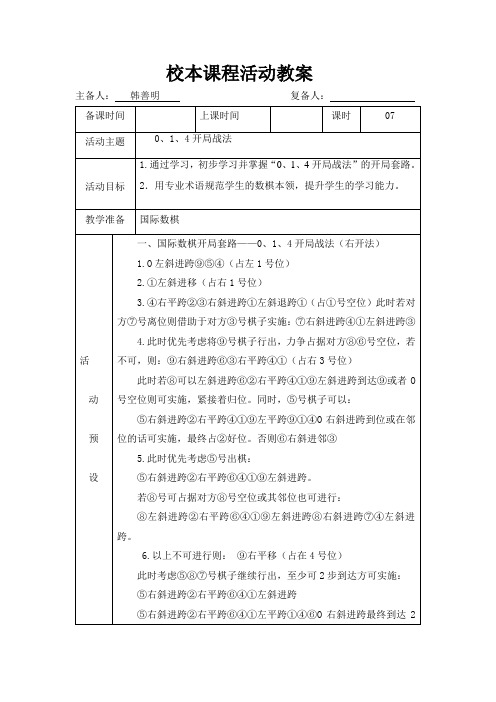
校本课程活动教案
主备人:韩善明复备人:
备课时间
上课时间
课时
07
活动主题
0、1、4开局战法
活动目标
1.通过学习,初步学习并掌握“0、1、4开局战法”的开局套路。
2.用专业术语规范学生的数棋本领,提升学生的学习能力。
教学准备
国际数棋
活
动
预
设
活
动
预
设
一、国际数棋开局套路——0、1、4开局战法(右开法)
魔方学习教程(入门至进阶)

RUR'U'R2
R:b
R'U2RU'2
R'FRUR'U'
R'F'R2U'
R:a
LU'2L'U2
LF'L'U'LU
LFL'2U
J:b
RUR'F'RUR'U'
R'FR2U'R'U'
J:a
L'U'LF L'U'LU
LF'L'2 ULU
G:d
LdF'L'2u'
LU'L'UL'uL2
G:c
OLL仍然分两步做(顶面出“+”字,顶面颜色统一)
OLL-1 3个公式
f RUR'U'f'
FRUR'U'F'
FRUR'U'F'
f RUR'U'f'
OLL-2 7个公式
RU'2R'U'RU
R'U'RU'R'
RU'2(R2U')2
R2U'2R
R2D'RU'2
R'DRU'2R
rUR'U'
r'FRF'
F'rUR'U'
OLL-2先背2个公式(总共处理7种情况)
① RUR'U RU'2R' ② R'U'RU' R'U2R
温梯法大尺寸白宝石单晶的生长

第27卷第3期人工晶体学报V ol.27No.3 1998年8月JOU RNA L OF SYN THET I C CRY ST A LS August,1998温梯法大尺寸白宝石单晶的生长*徐建卫周永宗周国清徐科邓佩珍徐军(中国科学院上海光学精密机械研究所,上海201800)提要:应用温梯法生长出直径120mm,质量为4kg的白宝石晶体。
进行了杂质定量分析和光谱分析,对晶体中杂质的来源进行了讨论。
确定了晶体有F心引起的紫外吸收和杂质离子的吸收。
关键词:白宝石晶体,温梯法,晶体生长,光谱Growth of Large-sized Sapphire Crystals byTemperature Gradient Technique(TGT)X u Jianwei Zhou Yongzong Zhou Guoqing X u K e Deng Peiz hen X u Jun (S hanghai Ins titute of Optics and Fine M echanics,Chinese Academy of Science,Shanghai201800,China)(Receiv ed23February1998,acc ep ted5Apr il1998)AbstractSapphire boules,120mm in diameter and4kg in weight have been grown by temperature gradient technique(TGT).Impurity elements of typical crystal are detected by glow discharge spectroscopy(GDMS)and the source of which are discussed.The transmission spectra isanalyzed,and the absorptions resulting from the F-centers and impurities are verified.Key words:sapphire crystal,tem perature gradient technique,crystal grow th,spectrum1引言白宝石(A-Al2O3)单晶具有一系列独特而优良的物理化学性质,特别是0.2~0.5L m波段有良好透光性,一直广泛应用于红外军事装备、卫星和空间技术的仪表及高功率激光器(如HF、DF、CO2激光器)的窗口材料,近来又成为重力波探测器中光学系统的首选材料[1]。
公共管理与政策研究中的实地实验:因果推断与影响评估的视角

公共管理与政策研究中的实地实验 因果推断与影响评估的视角
王思琦"
摘要 实验方法作为统计学因果推断的重要方法# 在公共管理与公共政策
研究中得到了越来越多的应用$ 实地实验作为实验方法的新发展# 相比传统的
实验室实验和调查实验具有更高的外在效度和现实应用价值# 被广泛用于变量
设为)# 万元' 没有读大学直接工作的年收入S$$#% 假设为+ 万元' 那么读大学
对于个体$年收入的因果效应$就是)# '+ s& 万元+
. All R现ig实ht世s界R中es'e研rv究ed者.面临的挑战是' 在任何给定的时间点' 只能观察到
或 S$$)% S$$#% 两者之一' 而不能同时观察到两者+ 如前面的例子那样' 在真实
之间的因果推断及政策与项目的影响评估中$ 论文在解释实验方法的统计学因
果推断基础( 并比较各类实验优劣势之后# 举例分析了实地实验的基本原理(
程序和可能出现的各种现实问题# 并以公共政策影响评估为切入点讨论了中国
公共管理与政策研究中使用实地实验方法面临的挑战与机遇$
关键词 因果推断!实地实验!准实验!自然实验!影响评估
$*%
一般来说' 我们规定干预变量"$取值# 或者)' 因此等号右边总有一项为
零+ 如果实施了干预$"$s)%' 我们将观察到干预导致的潜在结果S$$)%+ 如果
没有实施干预$"$s#%' 我们将观察到没有干预时的潜在结果S$$#%+
但在之前的例子中' 我们关注的是个体意义上的因果效应' 而在社会科学
JTAG-SMT2-NC编程模块用户手册说明书

410-308410-3081300 Henley Court Pullman, WA 99163509.334.6306 JTAG-SMT2-NC Programming Module for Xilinx ® FPGAsRevised March 2. 2015OverviewThe Joint Test Action Group (JTAG)-SMT2-NC is a compact, complete, and fully self-contained surface-mountprogramming module for Xilinx field-programmable gate arrays (FPGAs). The module can be accessed directly from all Xilinx Tools, including iMPACT, ChipScope ™, and EDK. Users can load the module directly onto a target board and reflow it like any other component.The JTAG-SMT2-NC uses a 3.3V main power supply and a separate Vref supply to drive the JTAG signals. All JTAG signals use high speed 24mA three-state buffers that allow signal voltages from 1.8V to 5V and bus speeds up to 30MBit/sec. The JTAG bus can be shared with other devices as the SMT2-NC signals are held at high impedance, except when actively driven during programming. The SMT2-NC module is CE certified and fully compliant with EU RoHS and REACH directives. The module routes the USB D+ (DP) and D- (DM) signals out to pads, providing the system designer with the ability to choose the type of USB connector and its location on the system board.Users can connect JTAG signals directly to the corresponding FPGA signals, as shown in Fig. 1. For best results, mount the module over a ground plane on the host PCB. Although users may run signal traces on top of the host PCB beneath the SMT2-NC, Digilent recommends keeping the area immediately beneath the SMT2-NC clear.Note: Keep the impedance between the SMT2-NC and FPGA below 100 Ohms to operate the JTAG at maximum speed. 1289567GND TCK TDI TMS GPIO1GPIO2GPIO0TDOVREF GNDVdd (3.3V)23D MD PThe JTAG-SMT2-NC∙ Small, complete, all-in-one JTAG programming/debuggingsolution for Xilinx FPGAs∙ Compatible with all Xilinx Tools∙ Compatible with IEEE 1149.7-2009 Class T0 – Class T4(includes 2-Wire JTAG)∙ GPIO pin allows debugging software to reset the processorcore of Xilinx’s Zynq ® platform ∙ Single 3.3V supply∙ Separate Vref drives JTAG signal voltages; Vref can be anyvoltage between 1.8V and 5V.∙ High-Speed USB2 port that can drive JTAG/SPI bus at up to30Mbit/sec (frequency settable by user)∙ SPI programming solution (modes 0 and 2 up to 30Mbit/sec,modes 1 and 3 up to 2Mbit/sec)∙ Small form-factor surface-mount module can be directlyloaded on target boards∙ USB D+ and D- signals routed to pads, allowing USB connectorto be placed anywhere on the host PCBFeatures include:JTAG-SMT2-NC Reference ManualThe SMT2-NC improves upon the SMT1 with the addition of three general purpose I/O pins (GPIO0– GPIO2) andsupport for interfacing IEEE 1149.7-2009 JTAG targets in both 2 and 4-wire modes.In addition to supporting JTAG, the JTAG-SMT2-NC also features eight highly configurable Serial Peripheral Interface (SPI) ports that allow communication with virtually any SPI peripheral (see Fig. 2). All eight SPI ports share the same SCK, MOSI, and MISO pins, so users may enable only one port at any given time. Table 1 summarizes the features supported by each port. The SMT2-NC supports SPI modes 0, 1, 2, and 3.USB2PortFigure 2. SMT2 SPI port connections.JTAG-SMT2-NC Reference ManualNote: The Xilinx Tools expect GPIO2/CS3 to be connected to the SRST_B pin on a Zynq chip. As a result, SPI ports 6 and 7 may not be used for SPI communication if the Xilinx Tools are going to be used to communicate with the SMT2.Software SupportThe JTAG-SMT2-NC has been designed to work seamlessly with Xilinx’s ISE® (iMPACT, ChipScope, EDK) and Vivado tool suites. The most recent versions of ISE and Vivado include all of the drivers, libraries, and plugins necessary to communicate with the JTAG-SMT2-NC. At the time of writing, the following Xilinx software included support for the SMT2-NC: Vivado 2014.1+, Vivado 2013.1+, and ISE 14.1+.The SMT2-NC is also compatible with ISE 13.1 – 13.4. However, these versions of ISE do not include all of the libraries, drivers, and plugins necessary to communicate with the SMT2-NC. In order to use the JTAG-SMT2-NC with these versions of ISE, version 2.5.2 or higher of the Digilent Plugin for Xilinx Tools package must be downloaded from the Digilent website and the ISE13 plugin must be manually installed as described in the included documentation.In addition to working seamlessly with all Xilinx tools, Digilent’s Adept software and the Adept software development kit (SDK) support the SMT2-NC module. For added convenience, customers may freely download the SDK from Digilent’s website. This Adept software includes a full-featured programming environment and a set of public application programming interfaces (API) that allow user applications to directly drive the JTAG chain.With the Adept SDK, users can create custom applications that will drive JTAG ports on virtually any device. Users may utilize the APIs provided by the SDK to create applications that can drive any SPI device supporting those modes. Please see the Adept SDK reference manual for more information.IEEE 1149.7-2009 CompatibilityThe JTAG-SMT2-NC supports several scan formats, including the JScan0-JScan3, MScan, and OScan0 - OScan7. It is capable of communicating in 4-wire and 2-wire scan chains that consist of Class T0 – T4 JTAG Target Systems (TS) (see Figs. 3 & 4).Figure 3. 4-Wire series topology.JTAG-SMT2-NC Reference ManualThe IEEE 1149.7-2009 specification requires any device that functions as a debug and test system (DTS) to provide a pull-up bias on the TMS and TDO pins. In order to meet this requirement, the JTAG-SMT2-NC features weak pull-ups (100K ohm) on the TMS, TDI, TDO, and TCK signals. Though not required in the specifications, the pull-ups on the TDI and TCK signals ensure that neither signal floats while another source is not driving them (see Fig. 5).VREF VREFUsers should place a current limiting resistor between the TMS pin of the SMT2-NC and the TMSC pin of the TS when using the JTAG-SMT2-NC to interface with a 1149.7 compatible TS. If a drive conflict occurs, this resistorshould prevent damage to components by limiting the amount of current flowing between the pins of each device. A 200 ohm resistor will limit the maximum current to 16.5mA when using a 3.3V reference (see Figs. 6 & 7). While this level of resistance should be sufficient for most applications, the value of the resistor may need to be adjusted to meet the requirements of the TS.2-Wire Star Topology4-Wire Star TopologyFigure 4. 4-Wire and 2-Wire star topology.Figure 5. Pull-ups on TMS, TDI, TDO, and TCK signals.JTAG-SMT2-NC Reference ManualIn most cases, users can avoid a drive conflict by having applications that use the SMT2-NC communicate with the TS in two-wire mode. Use the applications to reconfigure the TS to use the JScan0, JScan1, JScan2, or JScan3 scanformat prior to disabling the SMT2-NC’s JTAG port.The Adept SDK provides an example application that demonstrates how to communicate with a Class T4 TAP controller using the MScan, OScan0, and OScan1 scan formats.GPIO PinsThe JTAG-SMT2-NC has three general purpose I/O pins that are useful for a variety of different applications (GPIO0, GPIO1, and GPIO2). Each pin features high speed three-state input and output buffers. At power up, the JTAG-SMT2-NC disables these output buffers and places the signals in a high-impedance state. Each signal remains in a high-impedance state until a host application enables DPIO port 0 and configures the applicable pin as an output. When the host application disables DPIO port 0, all GPIO pins revert to a high-impedance state. Weak pull-ups (100K ohm) ensure that the GPIO signals do not float while not being actively driven (see Fig. 8).OEGPIOxFigure 7. 200 Ohm resistor limiting current flow.JTAG-SMT2-NC Reference ManualWhen customers use the JTAG-SMT2-NC to interface the scan chain of Xilinx’s Zynq platform, they should connect the GPIO2 pin of the SMT2-NC to the Zynq’s PS_SRST_B pin. This connection allows the Xilinx Tools to reset the Zynq’s processor core at various times during debugging operations. Please see the following “Application Examples” section for more information.Note: The Xilinx tools expect GPIO2 to be connected to the SRST_B pin on a Zynq chip. As a result, GPIO2 may not be used as a general purpose I/O if the Xilinx tools are going to be used to communicate with the SMT2. Note: DPIO port 0 can only be used while both JTAG and SPI are disabled.Application ExamplesExample 1: Interfacing a Zynq-7000 when VCCO_0 and VCCO_MIO1 use a common supplyFigure 9 demonstrates how to connect the JTAG-SMT2-NC to Xilinx’s Zynq-7000 silicon when the same voltage supplies both the VCCO_0 (Programmable Logic Bank 0 Power Supply) and the VCCO_MIO1 (Processor MIO Bank 1 Power Supply).In this case, the SMT2-NC has a 100K pull-up to VREF, which operates at the same voltage as VCCO_MIO1. This similar voltage makes it possible to eliminate the external pull-up that is normally required for the PS_SRST_B pin.Figure 9. Connecting the JTAG-SMT2-NC to Xilinx’s Zynq -7000.JTAG-SMT2-NC Reference ManualExample 2:Interfacing a Zynq-7000 that uses different voltages for VCCO_0 and VCCO_MIO1Figure 10 demonstrates how to connect the JTAG-SMT2-NC to Xilinx’s Zynq-7000 silicon when different voltages supply the VCCO_0 (Programmable Logic Bank 0 Power Supply) and VCCO_MIO1 (Processor MIO Bank 1 Power Supply). If the Zynq’s JTAG pins are operating at a different voltage than the PS_SRST_B, it requires an external buffer to adjust the level of the GPIO2 signal. The example in Fig. 10 demonstrates the use of an open drain buffer to allow for the possibility of adding a reset button.Figure 10. Use of an open drain buffer.JTAG-SMT2-NC Reference ManualExample 3:Interfacing a Zynq-7000 while retaining the Xilinx JTAG HeaderFigure 11 below demonstrates how to connect the JTAG-SMT2-NC to Xilinx’s Zynq-7000 silicon alongside Xilinx’s 14-pin JTAG header. In this example, the open drain buffers allow both the SMT2-NC and Xilinx JTAG Header to drive the PS_SRST_B pin, which may operate a different voltage than the Zynq’s JTAG pins.Figure 11. Open drain buffers allowing the SMT2-NC and JTAG Header to drive the PS_SRST_B pin.JTAG-SMT2-NC Reference ManualSupported Target DevicesThe JTAG-SMT2-NC is capable of targeting the following Xilinx devices:∙Xilinx FPGAs∙Xilinx Zynq-7000∙Xilinx CoolRunner™/CoolRunner-II CPLDs∙Xilinx Platform Flash ISP configuration PROMs∙Select third-party SPI PROMs∙Select third-party BPI PROMsThe following devices cannot be targeted by the JTAG-SMT2-NC:∙Xilinx 9500/9500XL CPLDs∙Xilinx 1700 and 18V00 ISP configuration PROMs∙Xilinx FPGA eFUSE programmingRemote device configuration is not supported for the JTAG-SMT2-NC when used with Xilinx’s iMPACT software.Note: Please see the "Introduction to Indirect Programming – SPI or BPI Flash Memory" help topic in iMPACT for a list of supported FPGA/PROM combinations.Note: Please see the “Configuration Memory Support” section of Xilinx UG908 for a list of the FPGA/PR OM combinations that Vivado supports.Programming Solutions Comparison ChartJTAG-SMT1 JTAG-SMT2 JTAG-SMT2-NC30 MHz 30 MHz 30 MHzMechanical InformationNote: All dimensions are shown in millimeters.General USB Signal Routing Guidelines∙Maintain a differential impedance of 90 ohms between the DP and DM signals.∙Keep DP and DM trace lengths within 50 mils of each other.∙Minimize DP and DM signal trace length. Keeping the trace length below 3 inches is recommended.∙When possible, route DP and DM on the plane closest to the ground plane.∙When possible, avoid routing the DP and DM signals through vias. If vias cannot be avoided, then keep them small and place the DP and DM traces on the same layer.∙When possible, avoid routing other traces near DP and DM.∙When possible, minimize or avoid the use of bends in the DP and DM traces. If 90 degree bends are necessary, then use two 45 degree turns or an arc instead of a single 90 degree turn.∙Do NOT route DP or DM near oscillators, crystals, switching regulators, clock generators, or inductors. Absolute Maximum RatingsDC Operating CharacteristicsAC Operating CharacteristicsThe JTAG-SMT2-NC’s JTAG signals operate according to the timing diagram in Fig . 12. The SMT2-NC supports JTAG/TCK frequencies from 30 MHz to 8 KHz at integer divisions of 30 MHz from 1 to 3750. Common frequencies include 30 MHz, 15 MHz, 10 Mhz, 7.5 MHz, and 6 MHz (see Table 2). The JTAG/TCK operating frequency can be set within the Xilinx tools.Note: P lease refer to Xilinx’s iMPACT documentation for more information.TMS/TDITCKTDOMounting to Host PCBsThe JTAG-SMT2-NC module has a moisture sensitivity level (MSL) of 6. Prior to reflow, the JTAG-SMT2-NC module must be dried by baking it at 125° C for 17 hours. Once this process has been completed, the module has a MSL of 3 and is suitable for reflow for up to 168 hours without additional drying.The factory finishes the JTAG-SMT2-NC signal pads with the ENIG process using 2u” gold over 150u” electroless nickel. This makes the SMT2-NC compatible with most mounting and reflow processes (see Fig. 13). The binding force of the solder is sufficient to hold the SMT2-NC firmly in place so mounting should require no additional adhesives.Figure 12. Timing diagram.Table 2. JTAG frequency support.Figure 13. JTAG-SMT2-NC reflow temperature over time.PackagingDigilent ships small quantities of less than 20 per order, individually packaged in antistatic bags. Digilent will pack and ship larger quantities in groups of 80 positioned in an antistatic bubble tray (see Fig. 14).Figure 14. JTAG-SMT2-NC shipping arrangement.410-308410-308。
板式精馏塔课程设计(乙醇-水体系)

酒精连续精馏塔的设计
学 专
院 业
设 计 者 学 号
指导老师 提交日期
化工原理课程设计
目 录
第一章 设计任务书...................................................................................................................1 1.1 题目 ............................................................................................................................1 1.2 原始数据 .....................................................................................................................1 1.3 任务 ............................................................................................................................1 1.4 作业分量 .....................................................................................................................1 第二章 工艺流程说明 ...............................................................................................................2 2.1 设计方案 .....................................................................................................................2 2.1.1 塔板类型 ............................................................................................................2 2.1.2 操作压强............................................................................................................2 2.1.3 加料方式 ............................................................................................................2 2.1.4 进料状况 ............................................................................................................2 2.1.5 加热方式 ............................................................................................................2 2.1.6 塔顶冷凝方式 .....................................................................................................2 2.1.7 热能利用方式 .....................................................................................................2 2.2 工艺流程图..................................................................................................................2 第三章 工艺计算 ......................................................................................................................4 3.1 物料衡算 .....................................................................................................................4 3.1.1 摩尔分数............................................................................................................4 3.1.2 摩尔流量............................................................................................................4 3.2 回流比.........................................................................................................................4 3.3 塔板数.........................................................................................................................5 3.3.1 理论塔板数 ........................................................................................................5 3.3.2 板效率 ...............................................................................................................7 3.3.3 实际塔板数 ........................................................................................................7 3.4 主要物性参数 ..............................................................................................................7 3.4.1 操作压强............................................................................................................7 3.4.2 平均摩尔质量.....................................................................................................8 3.4.3 平均密度............................................................................................................8 3.4.4 液体表面张力.....................................................................................................9 3.4.5 蒸汽粘度.......................................................................................................... 10 3.5 气液相负荷量 ............................................................................................................ 11 3.6 小结 .......................................................................................................................... 11
- 1、下载文档前请自行甄别文档内容的完整性,平台不提供额外的编辑、内容补充、找答案等附加服务。
- 2、"仅部分预览"的文档,不可在线预览部分如存在完整性等问题,可反馈申请退款(可完整预览的文档不适用该条件!)。
- 3、如文档侵犯您的权益,请联系客服反馈,我们会尽快为您处理(人工客服工作时间:9:00-18:30)。
FR (RFR(R U’) (R’ U y') (U R’ U’ R)FL (L' U L U' y) (L U2) (L' U2) (L U' L')FLy' (R U’) (R’ U y') (U R’ U’ R)BL (L U2 L' U) (L U2 r' F) (U'BL(L U' L' U) (U y') (L' U' L)BR(R' U R U' y) (RBR(R' U2) (R U') (R' U') (R U') (R' U R)槽位槽位FR (U R U' R') F (R'FR(l U) (L F' L' U') l'FL (U y') (R U' R') F (R' F' R)FL(L' U L U2 y) (R U R’)BL (U L U' L') x' U (L' U' L)BL(L U2) (L' U) (L U L') U (L U' L')BR(R U R U) (R U' R' U' R')BR(R' U R 槽位槽位FR (R'FRU' (R U' R' U) (R U R')FL (U' L' U L) F' (r U r')FL(U' y) (L U' L') U (L U L')BL (L U') (L' U' L) (U' L' U L U L')BLU' (L U' L') U (L U L')U' (R' U R) x' U' (R U R')(U' y) (R U') (R' U) (R U R')FR (U R U' R’)*3FR(U y') (R' U R U') (R' U' R)FL (U' L' U L)*3FLU (L' U L U') (L' U' L)BL (U L U' L’)*3BL(U y') (L' U L U') (L U' L')BR(R' U' R U)*2 (R' U' R)BRU (R' U R U') (R' U' R)槽位槽位FR (R U' R') (U y') (R' U R)FR(R U R') (U'U') (R U R' U') (R U R')FL (L' U L) (U' y) (L U' L')FL(L' U' L) y' (U' R U' R' U) (R U' R')BL (L U') x (L U') (L' U L')BLy (R' U' R) (U' y) (R U' R' U) (R U' R')BR(R' U R' F) (RBR(R' U' R) (U' y) (R U' R' U) (R U' R')槽位槽位FR (R U' R' U) (RFRU' (R U R') (R' F R F') (R U' R')FL (L' U' L U) (L' U2 L U) (L' U' L)FL(L' U' L) U2 (L' U' L U) (L' U' L)BL (L U' L' U) (L U2 L' U) (L U' L')BL(L U' L') (U' y) (R' U') (R (R' U R) U (R' U' R (R' U') (RFR (R U R’ U') (RFR(R’ F RFL (L' U) (L U') (L' U2) (L U') (L' U L)FL(L' U2) (L U L' U' L)BL (L U' L’) (U' L U L') U2 (L U' L')BLy (R' U2) (R U R' U' R)BR(R' U) (R U') (R' U2) (R U') (R' U R)BR(R' U2) (R U R' U' R) 槽位槽位FR (R U R’ U') (R U’ R’ U y') (U R’ U’ R)FR(RFL (L' U L U' y') (R U R') U (R U R')FLy' (RBL L2 y' (R U R’ U') y (L' U L')BL(L U2) (L' U') (L U L')BR(R' U R' U'BR(R' U’) (R U R' U') (R 槽位槽位FR (R U' R’ U') (R U' R’) (U y') (R’ U’ R)FR(U y') (R' U' RFL y' (R U' R’ U') (R U' R’) (U y') (R’ U’ R)FLU (L' U') (L U2) (L' U L)BL (L U' L’) (U L U L' U) (U y') (L’ U’ L)BLy (U R' U' R (R' U R (U R' U' RFR (R U'U' R' U y') (R' U R)FRU' (R U R' U') (RFL (L' U L U') (L' U L)FL(U' y) (L U L') U2 (L U' L')BL y (R' U R U') (R' U R)BLU' (L U L') U2 (L U' L')BR(R' U R U') (R' U R)BRU (r' U) (R U' R' U') r 槽位槽位FR (R U' R' U) (R U' R')FRU' (R U R' U) (R U R')FL y' (R U' R' U) (R U' R')FL(U' y) (L U L' U) (L U L')BL (L U' L' U) (L U' L')BLU' (L U L' U) (L U L')BRy (R U' R' U) (R U' R')BR(U' y) (R U R' U) (R U R')槽位槽位FR (R U R' U') (R U R')FRU' (R U' R') (U y') (R' U' R)FL (r U' r' F)*2FLy' U' (R U' R') (U y') (R' U' R)BL (L U L' U') (L U L')BLU' (L U' L') (U y') (L' U' L) y (R U R' U') (R U R')U (R' U' R U') (R' U' R)FR (R’ F RFR(U y') (R' U2 RFL (L' U' L U) (L' U' L)FLU (L' U2 L U2) (L' U L)BL y (R' U' R U) (R' U' R)BL(U y') (L' U2 L U2) (L' U L)BR(R' U' R U) (R' U' R)BRU (R' U2 R 槽位槽位FR U' (RFRU' (RFL U (L' U) (L U2) (L' U L)FL(U' y) (L U2) (L' U2) (L U' L')BL U (L U L') U2 (L U L')BLU' (L U2) (L' U2) (L U' L')BRU (R' U) (RBR(U' y) (R 槽位槽位FR U' (R U') (R' U2) (R U' R')FRR U R'FL U' (L' U' L) U2 (L' U' L)FLy' (R U R')BL U' (L U' L') U2 (L U' L')BLL U L' (U' y) (R U') (R' U2) (R U' R')y (R U R')FR y' (U R' U' R) (U' y) (R U R')FRy' (R’ U' R)FL U (L' U' L) (U' y) (L U L')FLL’ U' LBL y (U R' U' R) (U' y) (R U R')BLy (R’ U' R)BR(U R' U' R) (U' y) (R U R')BRR’ U' R 槽位槽位FR U' (R U R') y' (U R’ U' R)FR(U' y) (L’ U2) (L U’) (L’ U L)FL (U' y) (L U L'U) y' (L’ U' L)FLU' (L’ U2) (L U’) (L’ U L)BL U' (L U L' U) y' (L’ U' L)BL(U' y) (R’ U2) (R U’) (R’ U R)BR(R'BRU' (R’ U2) (R U’) (R’ U R)槽位槽位FR F (R'FRU (RFL U' (L' U L)FL(U y') (RBL x' U (L' U' L)BLU (L U2 L’) U (L U' L’)U' (R' U R)(U y') (L U2 L’) U (L U' L’)FR U R U’ R’FR(R U') (R' U2) (R U R')FL F' (r U r')FLF (RBL U (L U’ L’)BL(L U') (L' U2) (L U L')BRx' U' (R U R')BRf U R2 U' 槽位槽位FR (R U') (R' U) (R U') (R' U2) (R U' R')FRF' (L' U2) L FFL U (L' U2 L) (U' y) (L U' L')FLU2 (L' U' L) U' (L' U L)BL L' U2 (L2 U) (L'2 U) LBLy U2 (R' U' R) U' (R' U R)BRy' L' U2 (L2 U) (L'2 U) LBR(R' U) (R 槽位FRU' (RFLy' U' (RBLU' (L U2) (L' U y') (L' U' L)(R。