罗克韦尔推出了新型RightSight M30光电传感器
HDFDYI化纤丝饼外观检测系统
精品推介I Product Express产品的数据速率为200Hz,RMS噪声[lHz-100Hz]为0.02°/s;GYPR02300LD专为运动追踪和稳定应用而定制设计,数据速率为1700Hz,延迟为2mso GYPR03300采用优化型集成电路,更耐恶劣环境(振动校正系数为0.5°/h/g2),延迟为1ms,专为精密导航和稳定应用而设计。
内置的闭环电子设备具备多项主要优势,包括卓越的线性度、增强的信噪比,且在恶劣振动、冲击和温度环境中表现更为优异。
Tronics Microsystems的MEMS惯性传感器非常适合那些对高偏置稳定性和高性能惯性传感器有严格要求的系统制造商,主要应用包括精密导航、运动追踪和控制,以及光学防抖。
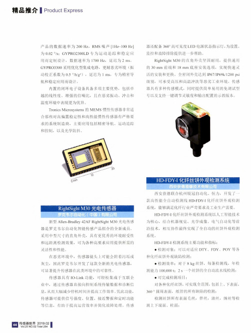
新型Allen-Bradley42AF RightSight M30光电传感器是罗克韦尔自动化智能传感产品组合的全新成员。
釆用中型尺寸的直角外壳,具有更优秀的环境耐受性和远距离检测效果,可为各种高要求应用提供所需的灵活性和性能。
在恶劣环境中,传感器镜头上可能会附着污垢或灰尘,因此罗克韦尔开发了这款全新的光电传感器,可显著提升传感器在此类环境中的可靠性。
传感器具有IO-Link功能,可轻松集成于互联企业中,通过传感器直接向控制系统传输数据和诊断信息,从而大幅减少停机时间并提高工作效率。
凭此功能,传感器可提供信号强度、位置、接近警报和定时功能等信息,有助于提高运营效率并简化故障处理。
传感器还配备360°高可见度LED电源状态指示灯,为设置、监控和故障排除提供进一步帮助。
RightSight M30的直角外壳坚固耐用,提供通用的30mm前端和18mm底座安装选项,实现快速灵活的安装和更换。
全密闭外壳达到IP67/IP69k/1200psi 级别,可承受高压和高温冲洗等恶劣工业环境。
传感器具有多种传感模式,同时提供简单易用的免调试型号以及支持一键调节灵敏度和输出配置的示教版本。
奥美晨曦系列微波传感器说明书

OS100 SERIES Mini-Infrared Transmitter e-mail:**************For latest product manuals: Shop online at User’s G ui d e***********************Servicing North America:U.S.A. Omega Engineering, Inc.Headquarters: Toll-Free: 1-800-826-6342 (USA & Canada only)Customer Service: 1-800-622-2378 (USA & Canada only)Engineering Service: 1-800-872-9436 (USA & Canada only)Tel: (203) 359-1660 Fax: (203) 359-7700e-mail:**************For Other Locations Visit /worldwideThe information contained in this document is believed to be correct, but OMEGA accepts no liability for any errors it contains, and reserves the right to alter specifications without notice.Table of ContentsSection ...................................................................PageSafety Warnings and IEC Symbols (iii)Caution and Safety Information (iii)Section 1 Introduction ....................................................................1-1Section 2Installation ......................................................................1-12.1 Unpacking and Inspection ......................................1-12.2 Electrical Connection ..............................................2-1Section 3Operation ........................................................................3-13.1 Main Board ................................................................3-13.2 Ambient Temperature ..............................................3-23.3 Atmospheric Quality ................................................3-33.4 Measuring Temperature ..........................................3-33.5 Alarm Setting ............................................................3-43.6 Adding Extension Cable...........................................3-4Section 4 Laser Sight Accessory ...................................................4-14.1 Warning and Cautions .............................................4-14.2 Operating the Laser Sight Accessory .....................4-1Section 5 Specifications .................................................................5-15.1 General .......................................................................5-15.2 Laser Sight Accessory (OS100-LS) ..........................5-2Section 6Emissivity Table .............................................................6-1iTable of FiguresFigure Description Page2-1Power Supply & Analog Output Connections ..........2-12-2 Alarm Output Connection ............................................2-13-1 Main PC Board ...............................................................3-23-2 Sensor..............................................................3-2Housing3-3 Optical Field of View .....................................................3-43-4Setting the Temperature Engineering Unit..................3-43-5Mounting Bracket OS100-MB .......................................3-53-6Water Cooling Jacket, OS100-WC ................................3-53-7Typical Water Cool Jacket Assembly ...........................3-53-8Air Purge Collar, OS100-AP..........................................3-63-9DIN Rail Mounting Adapter, OS100-DR ....................3-63-10NEMA-4 Aluminum Enclosure ....................................3-64-1Laser Sighting Accessory, OS100-LS ............................4-24-2Laser Warning Label ......................................................4-2iiSafety Warnings and IEC SymbolsThis device is marked with international safety and hazard symbols in accordance with IEC 1010. It is important to read and follow all precautions and instructions in this manual before operating or commissioning this device as it contains important information relating to safety and EMC. Failure to follow all safety precautions may result in injury and or damage to your calibrator. IEC symbols DescriptionCaution and Safety Information• If the equipment is used in a manner not specified in this manual, the protection provided by the equipment may be impaired.• The installation category is one (1).• There are no user replaceable fuses in this product• The output terminals of this product are for use with equipment (digital meters, chart recorders, etc,) which have no accessible five parts. Such equipment should comply with all the applicable safety requirements.• Do not operate the equipment in flammable or explosive environments.• All connections to the thermometer should be made via a shielded cable, 24 AWG stranded wire with the following ratings: 300V , 105°C (221°F), PVC insulation.• Power must be disconnected before making any electrical connections.• The power supply used to power the thermometer should be VDE or UL approved with the following ratings: 12 to 24vdc @150mA with overload protection of 500mA.iiiCaution, refer to accompanying documentsDirect Current Laser SymbolFrame or ChassisNOTES: ivSection 1 - IntroductionThe low cost OS101 mini-infrared transmitter provides non-contacttemperature measurement for industrial applications. The unit measures atemperature range of -18 to 538°C (0-1000°F) and provides a linear analogoutput of either 4-20 mA, 0-5 VDC, K type TC, 1 mV/°C, or 1 mV/°F.The new OS102 mini-infrared transmitter has all the functions of OS101plus a built-in LED display that shows the measured temperature indegrees F or degrees C which is switchable in the field.The miniature sensor head design 2.5 cm dia. x 6.3 cm Length (1" x 2.5") isideal for measuring temperature in confined, and hard to reach places.The aluminum sensor head as well as the rugged electronic housing (Diecast Aluminum) are NEMA-4 rated.The sensor head is connected to the electronic housing via a 1.82 m (6 feet)shielded cable as standard. The unit provides field adjustable alarmoutput.Section 2 - Installation2.1UnpackingRemove the packing list and verify that you have received all yourequipment. If you have any questions about the shipment, please callCustomer Service at:1-800-622-2378 or 203-359-1660. We can also be reached on the internet:e-mail:**************When you receive the shipment, inspect the container and equipment forany signs of damage. Note any evidence of rough handling in transit.inspection. After examination and removing contents, save packing material and carton in theevent reshipment is necessary.The following items are supplied in the box:• The infrared transmitter including the sensor head and the 1.82 m(6 feet) shielded cable• User's Manual• Mounting Nut1-1The following describes the ordering information:OS102 or OS101 - MA- *,**, where The following optional accessories are available:Here are the Features of OS101 and OS102 infrared transmitters:2.2Electrical Connection Sensor Head Cable - The Sensor head is pre-wired to a 1.8 m (6 feet)shielded cable. Plug & lock-in the male connector to the mating female connector on the aluminum housing.Power & Output Connection - Open the cover of the main aluminum housing. Slide the cable through the strain relief and connect the wires to the terminal block on the board as shown in Fig. 2-1. For Alarm output connection, refer to Fig. 2-2.2-1MA - 4/20 mA output V1 - 0 to 5 VDC output K - Thermocouple output, K type MV - Millivolt output C - 1 mV/°C output F - 1 mV/°F output HT- High temperature sensor head3-1Figure 2-2. Alarm Output Connection Section 3 - Operation3-1Main BoardThe Main Board is shown in Fig. 3-1. Here are the important components on the board:(1) - Terminal Block for Power & Output connections(2) - Single Turn Potentiometer to adjust Emissivity in tenths (0.x_)(3) - Single Turn Potentiometer to adjust Emissivity in hundreds (0._x)(4) -Slide switch to select between real time (Normal Operation) and alarm set point(5) - Alarm set point adjust, P4(6) - Sensor Head connection(7) - Input Zero adjust, P3(8) - Input Span adjust, P2(9) - Output Zero adjust, P5(10) - Output Span adjust, P6Figure 3-1. Main PC Board3.2Ambient TemperatureThe Sensing head can operate in an ambient temperature of 0 to 70°C (32to 158°F). The Sensing head in the high temperature model (-HT) can operate in an ambient temperature of 0 to 85°C (32 to 185°F) without any cooling required. The Sensing head can operate up to 200°C (392°F) using the water cool jacket accessory OS100-WC (See Fig. 3-6).There is a warm up period of 3 minutes after power up. After the warm up period, temperature measurement can be made.When the ambient temperature around the sensor head changes abruptly,the sensor head goes through thermal shock. It takes a certain amount of time for the sensor head to stabilize to the new ambient temperature. For example, it takes about 30 minutes for the sensor head to stabilize going from 25°C to 50°C (77 to 122°F) ambient temperature.The sensor head dimensions are shown in Fig. 3-2.Figure 3-2. Sensor Housing3-23-33.3Atmospheric QualityEnvironments with smoke, dust, and fumes dirty up the optical lens, and cause erroneous temperature readings. To keep the surface of the optical lens clean, the air purge collar accessory is recommended, OS100-AP , See Fig. 3-7.3.4Measuring TemperatureBefore starting to measure temperature, make sure that the following check list is met:ߜ The power and analog output connections are made (Fig. 2-1).ߜThe sensor head is connected to the main unit.ߜThe slide switch (SW1) on the main board is set to real time (Fig. 3-1).ߜThe target is larger than the optical field of view of the sensor head (Fig. 3-3).ߜThe emissivity adjustment on the main board is set properly (Fig. 3-1).ߜThe output load is within the product specification.On OS102 transmitters, follow these additional steps:ߜ The temperature display is set to °F or °C (Fig. 3-4)ߜ For 4-20mA output models, make sure an output load is added, ie. 250ohms.Figure 3-3. Optical Field Of ViewFigure 3-4. Setting the Temperature Engineering Unit3.5Alarm SettingThe unit provides 0-100% alarm set point adjustment. Here is an exampleof an alarm setting.• An OS101-MA(4/20 mA output), the alarm is to be set at 400°Ftemperature.• Connect the alarm output as shown in Fig. 2-2.• Set the slide switch (SW1) on the main board to the Alarm position.• Measure the analog output, and set the Potentiometer P4 until theoutput reads 10.4 mA which is 40% (400°F) of the temperature range.40 x (20-4)[10.4mA=+ 4]100• Set the slide switch (SW1) back to the Real Time position.• If the temperature reading is below the alarm set point, the alarmoutput stays high, otherwise it goes low.On the OS102, you can set the alarm set point directly based on thetemperature display.3.6Adding Extension CableYou can add extension cable between the Sensor Head and the mainelectronic housing up to 15.2 m (50 feet). After adding the extension cable,the Zero input potentiometer, P3 may be re-adjusted. (See Fig. 3-1, forproper analog output reading)The following figures show the mounting bracket (OS100-MB), Watercooling jacket (OS100-WC), Air purge collar (OS100-AP), DIN RailMounting adapter (OS-100-DR), and the main aluminum enclosure. TheDIN Rail Mounting adapter (OS100-DR) is mounted to the bottom of themain aluminum enclosure using two 4-40 screws.A typical water cool jacket assembly is shown in Fig. 3-7, on the following page.1. Mounting Nut2. Mounting Bracket3. Water Cool Jacket4. Sensor Head3-4Figure 3-5. Mounting Bracket OS100-MBFigure 3-6. Water Cooling Jacket, OS100-WCFigure 3-7. Typical Water Cool Jacket Assembly3-5Figure 3-8. Air Purge Collar, OS100-APFigure 3-9. DIN Rail Mounting Adapter, OS-100-DRFigure 3-10. NEMA-4 Aluminum Enclosure3-6Section 4 - Laser Sight Accessory4.1Warning and Cautionsbelow:•Use of controls or adjustments or performance of procedures other than those specified here may result in hazardous radiation exposure.• Do not look at the laser beam coming out of the lens or view directly with optical instruments - eye damage can result.• Use extreme caution when operation the laser sight accessory • Never point the laser accessory at a person • Keep out of the reach of all children4.2Operating the Laser Sight AccessoryThe laser sight accessory screws onto the front of the sensor head. This accessory is only used for alignment of the sensor head to the target area.After the alignment process, the accessory has to be removed from the front of the sensor head before temperature measurement.The laser sight accessory is powered from a small compact battery pack (included with the accessory). Connect the battery pack to the accessory using the cable provided. Aim at the target, and turn on the battery power using the slide switch on the battery pack. Adjust the sensor head position so that the laser beam points to the center of the target area. Turn off the battery pack, and remove the laser sighting accessory from the sensor head. See Fig. 4-1 for reference.4-14-2Figure 4-2. Laser Warning LabelSection 5 - Specifications5.1 - GeneralTemperature Range-18 to 538°C (0 to 1000°F)Accuracy @ 22°C (72°F)±2% of Rdg. or 2.2°C (4°F) whichever is ambient temperature & greateremissivity of 0.95 or greaterOptical Field of View6:1 (Distance/Spot Size)Repeatability±1% of Rdg.Spectral Response 5 to 14 micronsResponse Time150 msec (0 to 63% of final value)Emissivity Range0.1 to 0.99, adjustableOperating Ambient TemperatureMain Transmitter0 to 50°C (32 to 122°F)Sensor Head0 to 70°C (32 to 158°F)Sensor Head (-HT Model)0 to 85°C (32 to 185°F)Sensor Head with OS100-WC(Water Cooling Jacket)0 to 200°C (32 to 392°F)Operating Relative Humidity Less than 95% RH, non-condensingWater Flow Rate for OS100-WC0.25 GPM, room temperatureThermal Shock About 30 minutes for 25°Cabrupt ambient temperature change Warm Up Period 3 minutesAir Flow Rate for OS100-AP 1 CFM (0.5 Liters/sec.)Power12 to 24 VDC @ 100 mAAnalog OutputsMV-F 1 mV/°FMV-C 1 mV/°CK K Type TC - OS101 onlyMA 4 to 20 mAV10 to 5 VDCOutput Load requirementsMin. Load (0 to 5VDC) 1 K-OhmsMax. Load (4 to 20 mA)(Supply Power - 4 )/20 mATransmitter Housing NEMA-4 & IP65, Die Cast AluminumSensor Head Housing NEMA-4 , AluminumAlarm Output Open Drain, 100 mAAlarm Set Point0 to 100% , Adjustable via P4Alarm Deadband14°C (25°F)5-15-25.1 - General Con’t.DimensionsSensor Head25.4 OD. x 63.5 mm L(1" OD. x 2.5" L)Main Housing, OS10165.5 W x 30.5 H x 115.3 mm L(2.58" W x 1.2" H x 4.54" L)Main Housing, OS10265.5 W x 55.9 H x 115.3 mm L(2.58" W x 2.2" H x 4.54" L)Weight 272 g (0.6 lb)5.2Laser Sight Accessory (OS100-LS)Wavelength (Color)630 - 670 nm (Red)Operating Distance (Laser Dot)Up to 9.1 m (30 ft.)Max. Output Optical Power Less than 1 mW at 22°F ambienttemperature.European Classification Class 2, EN60825-1/11.2001Maximum Operating current45 mA at 3 VDCFDA Classification Complies with 21 CFR 1040.10,Class II Laser ProductBeam Diameter 5 mmBeam Divergence< 2 mradOperating Temperature0 to 50°C (32 to 122°F)Operating Relative Humidity Less than 95% RH, non-condensingPower Switch ON / OFF , Slide switch on the BatteryPackPower Indicator Red LEDPower Battery Pack, 3 VDC (Consists of two 1.5VDC AA size Lithium Batteries) Laser Warning Label Located on the head sight circumferenceIdentification Label Located on the head sight circumferenceDimensions38 DIA x 50.8 mm L(1.5" DIA x 2" L)Section 6 - Emissivity Table6-1Material Emissivity (ε)Aluminum – pure highly polished plate . . . . . . . . . . . . . . . . . . . . . . . . 0.04 to 0.06Aluminum – heavily oxidized . . . . . . . . . . . . . . . . . . . . . . . . . . . . . . . 0.20 to 0.31Aluminum – commercial sheet . . . . . . . . . . . . . . . . . . . . . . . . . . . . . . . . . . . . 0.09Brass – dull plate. . . . . . . . . . . . . . . . . . . . . . . . . . . . . . . . . . . . . . . . . . . . . . 0.22Brass – highly polished, 73.2% Cu, 26.7% Zn. . . . . . . . . . . . . . . . . . . . . . . . . 0.03Chromium – polished. . . . . . . . . . . . . . . . . . . . . . . . . . . . . . . . . . . . . 0.08 to 0.36Copper – polished. . . . . . . . . . . . . . . . . . . . . . . . . . . . . . . . . . . . . . . . . . . . . 0.05Copper – heated at 600°C (1112°F). . . . . . . . . . . . . . . . . . . . . . . . . . . . . . . 0.57Gold – pure, highly polished or liquid. . . . . . . . . . . . . . . . . . . . . . . . . 0.02 to 0.04Iron and steel (excluding stainless)– polished iron . . . . . . . . . . . . . . . . 0.14 to 0.38Iron and steel (excluding stainless)– polished cast iron. . . . . . . . . . . . . . . . . . . 0.21Iron and steel (excluding stainless)– polished wrought iron . . . . . . . . . . . . . . . 0.28Iron and steel (excluding stainless)– oxidized dull wrought iron . . . . . . . . . . . . 0.94Iron and steel (excluding stainless)– rusted iron plate . . . . . . . . . . . . . . . . . . . 0.69Iron and steel (excluding stainless)– polished steel. . . . . . . . . . . . . . . . . . . . . . 0.07Iron and steel (excluding stainless)– polished steel oxidized at600°C (1112°F). . . . . . . . . . . . . . . . . . . . 0.79Iron and steel (excluding stainless)– rolled sheet steel . . . . . . . . . . . . . . . . . . . 0.66Iron and steel (excluding stainless)– rough steel plate . . . . . . . . . . . . . 0.94 to 0.97Lead – gray and oxidized . . . . . . . . . . . . . . . . . . . . . . . . . . . . . . . . . . . . . . . 0.28Mercury . . . . . . . . . . . . . . . . . . . . . . . . . . . . . . . . . . . . . . . . . . . . . 0.09 to 0.12Molybdenum filament . . . . . . . . . . . . . . . . . . . . . . . . . . . . . . . . . . . . 0.10 to 0.20Nickel – polished . . . . . . . . . . . . . . . . . . . . . . . . . . . . . . . . . . . . . . . . . . . . . 0.07Nickel – oxidized at 649 to 1254°C (1200°F to 2290°F). . . . . . . . . . . 0.59 to 0.86Platinum – pure polished plate . . . . . . . . . . . . . . . . . . . . . . . . . . . . . . 0.05 to 0.10Platinum – wire . . . . . . . . . . . . . . . . . . . . . . . . . . . . . . . . . . . . . . . . 0.07 to 0.18Silver – pure and polished . . . . . . . . . . . . . . . . . . . . . . . . . . . . . . . . . 0.02 to 0.03Stainless steel – polished . . . . . . . . . . . . . . . . . . . . . . . . . . . . . . . . . . . . . . . . 0.07Stainless steel – Type 301 at 232 to 942°C (450°F to 1725°F). . . . . . . 0.54 to 0.63Tin – bright . . . . . . . . . . . . . . . . . . . . . . . . . . . . . . . . . . . . . . . . . . . . . . . . . 0.06Tungsten – filament . . . . . . . . . . . . . . . . . . . . . . . . . . . . . . . . . . . . . . . . . . . . 0.39Zinc – polished commercial pure . . . . . . . . . . . . . . . . . . . . . . . . . . . . . . . . . . 0.05Zinc – galvanized sheet. . . . . . . . . . . . . . . . . . . . . . . . . . . . . . . . . . . . . . . . . 0.23M E T A L S6-2Material Emissivity (ε) Asbestos Board . . . . . . . . . . . . . . . . . . . . . . . . . . . . . . . . . . . . . . . . . . . . . . .0.96 Asphalt, tar, pitch . . . . . . . . . . . . . . . . . . . . . . . . . . . . . . . . . . . . . . .0.95 to 1.00 Brick– red and rough . . . . . . . . . . . . . . . . . . . . . . . . . . . . . . . . . . . . . . . . . .0.93 Brick– fireclay . . . . . . . . . . . . . . . . . . . . . . . . . . . . . . . . . . . . . . . . . . . . . . .0.75 Carbon– filament . . . . . . . . . . . . . . . . . . . . . . . . . . . . . . . . . . . . . . . . . . . . .0.53 Carbon– lampblack - rough deposit . . . . . . . . . . . . . . . . . . . . . . . . . .0.78 to 0.84 Glass- Pyrex, lead, soda . . . . . . . . . . . . . . . . . . . . . . . . . . . . . . . . . .0.85 to 0.95 Marble– polished light gray . . . . . . . . . . . . . . . . . . . . . . . . . . . . . . . . . . . . .0.93 Paints, lacquers, and varnishes– Black matte shellac . . . . . . . . . . . . . . . . . . . .0.91 Paints, lacquers, and varnishes– aluminum paints . . . . . . . . . . . . . . . .0.27 to 0.67 Paints, lacquers, and varnishes– flat black lacquer . . . . . . . . . . . . . . .0.96 to 0.98 Paints, lacquers, and varnishes– white enamel varnish . . . . . . . . . . . . . . . . . .0.91 Porcelain– glazed . . . . . . . . . . . . . . . . . . . . . . . . . . . . . . . . . . . . . . . . . . . . .0.92 Quartz– opaque . . . . . . . . . . . . . . . . . . . . . . . . . . . . . . . . . . . . . . . .0.68 to 0.92 Roofing Paper . . . . . . . . . . . . . . . . . . . . . . . . . . . . . . . . . . . . . . . . . . . . . . .0.91 Tape– Masking . . . . . . . . . . . . . . . . . . . . . . . . . . . . . . . . . . . . . . . . . . . . . .0.95 Water . . . . . . . . . . . . . . . . . . . . . . . . . . . . . . . . . . . . . . . . . . . . . . . .0.95 to 0.96 Wood– planed oak . . . . . . . . . . . . . . . . . . . . . . . . . . . . . . . . . . . . . . . . . . . .0.90 NONMETALSNOTES:6-3NOTES: 6-4OMEGA’s policy is to make running changes, not model changes, whenever an improvement is possible. T his affords our customers the latest in technology and engineering.OMEGA is a trademark of OMEGA ENGINEERING, INC.© Copyright 2017 OMEGA ENGINEERING, INC. All rights reserved. T his document may not be copied, photocopied, reproduced, translated, or reduced to any electronic medium or machine-readable form, in whole or in part, without the prior written consent of OMEGA ENGINEERING, INC.FOR WARRANTY RETURNS, please have the following information available BEFORE contacting OMEGA:1. P urchase Order number under which the product was PURCHASED,2. M odel and serial number of the product under warranty, and3. Repair instructions and/or specific problems relative to the product.FOR NON-WARRANTY REPAIRS, consult OMEGA for current repair charges. Have the following information available BEFORE contacting OMEGA:1. Purchase Order number to cover the COST of the repair,2. Model and serial number of the product, and 3. Repair instructions and/or specific problems relative to the product.RETURN REQUESTS/INQUIRIESDirect all warranty and repair requests/inquiries to the OMEGA Customer Service Department. BEFORE RET URNING ANY PRODUCT (S) T O OMEGA, PURCHASER MUST OBT AIN AN AUT HORIZED RET URN (AR) NUMBER FROM OMEGA’S CUST OMER SERVICE DEPART MENT (IN ORDER T O AVOID PROCESSING DELAYS). The assigned AR number should then be marked on the outside of the return package and on any correspondence.T he purchaser is responsible for shipping charges, freight, insurance and proper packaging to preventbreakage in transit.WARRANTY/DISCLAIMEROMEGA ENGINEERING, INC. warrants this unit to be free of defects in materials and workmanship for a period of 25 months from date of purchase. OMEGA’s WARRANTY adds an additional one (1) month grace period to the normal two (2) year product warranty to cover handling and shipping time. This ensures that OMEGA’s customers receive maximum coverage on each product.If the unit malfunctions, it must be returned to the factory for evaluation. OMEGA’s Customer Service Department will issue an Authorized Return (AR) number immediately upon phone or written request. Upon examination by OMEGA, if the unit is found to be defective, it will be repaired or replaced at no charge. OMEGA’s WARRANT Y does not apply to defects resulting from any action of the purchaser, including but not limited to mishandling, improper interfacing, operation outside of design limits, improper repair, or unauthorized modification. T his WARRANT Y is VOID if the unit shows evidence of having been tampered with or shows evidence of having been damaged as a result of excessive corrosion; or current, heat, moisture or vibration; improper specification; misapplication; misuse or other operating conditions outside of OMEGA’s control. Components in which wear is not warranted, include but are not limited to contact points, fuses, and triacs.OMEGA is pleased to offer suggestions on the use of its various products. However, OMEGA neither assumes responsibility for any omissions or errors nor assumes liability for any damages that result from the use of its products in accordance with information provided by OMEGA, either verbal or written. OMEGA warrants only that the parts manufactured by the company will be as specified and free of defects. OMEGA MAKES NO OTHER WARRANTIES OR REPRESENTATIONS OF ANY KIND WHATSOEVER, EXPRESSED OR IMPLIED, EXCEPT THAT OF TITLE, AND ALL IMPLIED W ARRANTIES INCLUDING ANY W ARRANTY OF MERCHANTABILITY AND FITNESS FOR A PARTICULAR PURPOSE ARE HEREBY DISCLAIMED. LIMITATION OF LIABILITY: The remedies of purchaser set forth herein are exclusive, and the total liability of OMEGA with respect to this order, whether based on contract, warranty, negligence, indemnification, strict liability or otherwise, shall not exceed the purchase price of the component upon which liability is based. In no event shall OMEGA be liable for consequential, incidental or special damages.CONDITIONS: Equipment sold by OMEGA is not intended to be used, nor shall it be used: (1) as a “Basic Component” under 10 CFR 21 (NRC), used in or with any nuclear installation or activity; or (2) in medical applications or used on humans. Should any Product(s) be used in or with any nuclear installation or activity, medical application, used on humans, or misused in any way, OMEGA assumes no responsibility as set forth in our basic WARRANT Y /DISCLAIMER language, and, additionally, purchaser will indemnify OMEGA and hold OMEGA harmless from any liability or damage whatsoever arising out of the use of theProduct(s) in such a manner.Where Do I Find Everything I Need forProcess Measurement and Control?OMEGA…Of Course!Shop online at TEMPERATUREM U Thermocouple, RTD & Thermistor Probes, Connectors,Panels & AssembliesM U Wire: Thermocouple, RTD & ThermistorM U Calibrators & Ice Point ReferencesM U Recorders, Controllers & Process MonitorsM U Infrared PyrometersPRESSURE, STRAIN AND FORCEM U Transducers & Strain GagesM U Load Cells & Pressure GagesM U Displacement TransducersM U Instrumentation & AccessoriesFLOW/LEVELM U Rotameters, Gas Mass Flowmeters & Flow ComputersM U Air Velocity IndicatorsM U Turbine/Paddlewheel SystemsM U Totalizers & Batch ControllerspH/CONDUCTIVITYM U pH Electrodes, Testers & AccessoriesM U Benchtop/Laboratory MetersM U Controllers, Calibrators, Simulators & PumpsM U Industrial pH & Conductivity EquipmentDATA ACQUISITIONM U Communications-Based Acquisition SystemsM U Data Logging SystemsM U Wireless Sensors, Transmitters, & ReceiversM U Signal ConditionersM U Data Acquisition SoftwareHEATERSM U Heating CableM U Cartridge & Strip HeatersM U Immersion & Band HeatersM U Flexible HeatersM U Laboratory HeatersENVIRONMENTALMONITORING AND CONTROLM U Metering & Control InstrumentationM U RefractometersM U Pumps & TubingM U Air, Soil & Water MonitorsM U Industrial Water & Wastewater TreatmentM U pH, Conductivity & Dissolved Oxygen InstrumentsM3572/1217。
Su-27 DCS Flaming Cliffs Flight Manual CN

苏-27 的 41 项纪录................................................................................... 17
先进前线战斗机......................................................................................... 2
从 T-10 到 T-10S ..................................................................................... 10
简介 ........................................................................................................ VI
SU-27 历史 ............................................................................................... 2
开始服役 ................................................................................................ 19
总体设计 ................................................................................................. 22
IRS-M30激光反射式传感器
CCD测宽测厚系统产品介绍一、产品概述CCD测宽是一套高精度物料宽度测量系统,它由控制器、CCD传感器、背光器和LED大显示器组成。
系统采用高速微处理芯片及RS485通讯方式,实时高速监测、显示物料宽度,并根据设定的标准值、偏差值、极限值进行三色或五色声光报警;通过总线接口可与上位机进行实时数据交换,支持远程控制。
二、产品照片三、产品特点●CCD传感器检测精度高,检测速度快,稳定性高。
●实时检测物料并按配方报警,由PROFIBUS/CCLINK/EtherNet等总线与上位机系统通讯。
●系统测量范围宽,扩展性好,可根据客户需要深度定制。
●体积小、便于安装。
四、产品技术参数通讯方式PROFIBUS/CCLink/以太网总线/RS485检测范围0~1000mm检测精度检测范围×1‰、单位mm供电DC24V/3A保护电路防止电源反接、输出过电流和输出电涌保护防护等级IP54工作温度0°C-+50°C(无冻结)工作湿度5-80%RH(无凝结)适用场合非透明材料的测边和测宽,主要用于轮胎行业挤出生产线的胶条宽度测试。
背光器供电AC220V/0.5A/50Hz(由用户提供)背光模式LED背光大显示器指标 2.3INCH,4位,可配三色或5色声光报警灯五、产品及配套设施清单序号名称型号规格配套说明1控制器SPRO320Si-CCD-W-DP-P/SPRO320Si-CCD-W-CC-P/SPRO320Si-CCD-W-ENT-P/SPRO320Si-CCD-W-00-P单CCD测宽应用型号DP为profibus总线接口CC为CCLINK总线接口ENT为以太网总线接口00为不带总线通讯功能SPRO320Si-CCD-W2-DP/SPRO320Si-CCD-W2-CC/SPRO320Si-CCD-W2-ENT/SPRO320Si-CCD-W2-00双CCD测宽应用型号DP/CC/ENT同上,为适配的通讯总线接口注:测宽超过900mm上选用2CCD传感器CCD-44必选3CCD传感器调试面板C0P-50必选4CCD调整座ZK40-XXX 必选,XXX表示高度调整范围,常规长度有300mm、500mm5CCD传感器线缆CCN-B-XXX-2.0必选,专用线缆,XXXX表示线缆长度,有3000(3米)、5000(5米)、7000(7米)可选6大显示器LED-400-XPB 选配,X为灯光报警数量,B表示蜂鸣器报警,如LED-400-0P为不带声光报警型号;LED-400-5PB 为5色灯光报警+蜂鸣器报警;7大显示线缆TCN-P-XXX-2.0选配,专用线缆,XXXX表示线缆长度,有3000(3米)、5000(5米)、7000(7米)可选8背光器GZ-900-LED-50必选,共有300、600、900、1200、1500五种长度可选(mm)9背光器安装座CCD-BGQ-12必选10控制器配件SPRO320Si-AZPJ(V2.0)必选11龙门架CCD-AZJ-XXX-YYY 选配,XXX为龙门架高度,YYY 为龙门架内宽六、安装尺寸图安装尺寸图见产品安装尺寸图文档七、安装要求及安装示意图安装要求及安装示意图见产品安装示意图文档八、产品应用实例具体应用见产品应用照片文档。
切尔哈姆合光电感应传感器E58-30系列用户手册说明书

Models covered in this manual:AC/DC Models w/ CableAC/DC Models w/ ConnectorDC-only Models w/ CableDC-only Models w/ ConnectorLight Operate Dark Operate Light Operate Dark Operate Light Operate Dark Operate Light Operate Dark Operate PolarizedE58-30RP10-GLE58-30RP10-GDE58-30RP10-GLPE58-30RP10-GDPE58-30RP10-HLE58-30RP10-HDE58-30RP10-HLPE58-30RP10-HDPInstallation Instructions—E58-30 Series Polarized Reflex Sensors Document 108623-400 Rev 02Cutler-Hammer Photoelectric SensorsWARNING!•These products are not designed, tested, or recommended for use in human safety applications.•This product has no user-serviceable parts—please return to the factory for repairs. The cable clamp on the back of the sensor does not require adjustment. Any attempt to tighten or loosen this part will compromise sealing and void warranty.•AC/DC connector version sensors are equipped with an AC-type connector. The use of DC power with AC-type connectors may not conform with established standards.D C 10 t o 30 V*Note: No connection when using thru-beam sources+V( - )D C 15 t o 30 V*Note: No connection when using thru-beam sources+VAC/DC Models (DC Connection, see Warning above)DC ModelsWIRING DIAGRAMSFor wiring cable versions, the color codes shown are the actual wire colors emanating from the sensor. For connector versions, the pin numbering and color codes shown are typical of several manufacturers, however, variations are possible. In case of discrepancies, rely on function indicated and pin location rather than pin number or color code.AC/DC Models (AC Connection)A C 20 t o 264 V*Note: No connection when using thru-beam sources L1L2REFLEX SENSINGA reflex sensor has both a light source and detector in the same unit. The source sends a beam of light to a retroreflector which returns it back to the detector. A break in the light beam causes the sensor to change output state.The polarizing filter conditions the beam so that light reflected off the retroreflector is detected,but light reflected by the target is not. This ensures reliable detection of shiny targets.MOUNTING LOCATION AND SET-UPLocate the sensor and retroreflector onopposite sides of the target. Ensure that the area of the target to be detected will block the entire effective beam.With power applied to the sensor, aim the unit directly at the center of the retroreflector. Move the sensor back and forth in one plane to find the extreme positions where the output indicator goes “off” (for light-operate mode, or “on” for dark-operate mode). Position the sensor midway between the two extremes.Repeat this procedure for the other plane. After alignment, tighten all mounting screws. An alternate method is to look at the retroreflector with your eye as close to the sensor as possible and align the sensor until reflected light is brightest.Stretch wrap material over a shiny surface may reflect enough light to false trigger a polarized reflex sensor. In this case, tilt the alignment axis of the sensor relative to the shiny surface.USING RETROREFLECTIVE TAPERetroreflective tapes can have vastly different properties than corner-cube reflectors. Polarized reflex sensors will not function with some types of tape (use only corner-cube style tape). Also,signal strength can drop dramatically as thedistance between tape and sensor is reduced. If you intend to use tape with a polarized sensor,especially if mounted closer than 18 inches from the sensor, we recommend that you test your particular tape prior to installation.MOUNTINGhole, or a variety of accessory mountingbrackets.*This manual also covers the model numbers above with the options suffix -FC and -FSC (see “Specifications” on last page for differences)INTRODUCTIONThe E58-30 Photoelectric Sensor line was designed to withstand your harshest physical,chemical, and optical environments. Tough environments like:Automotive—Survives constant exposure to lubricants, cutting fluids, coolants and glycols,plus flying metal cutting chips and tough physical abuse.Food processing—Unaffected by high-pressure chemical washdowns using sanitizers,surfactants, and cleaning agents including diluted bases & acids.Forest industry—Resists anti-fungal and anti-stain agents, wood preservatives, pitch and lubricants.RUGGED PHYSICAL CONSTRUCTION A strong metal housing with mechanical seals and surface mount electronics stand up to heavy shock and vibration.EXCEPTIONAL ENVIRONMENTAL PROTECTION AND CHEMICAL COMPATIBILITYExtensive research dictated the choice of materials used in this sensor to provide exceptional protection in harsh ponents are mechanically assembled using Viton seals to ensure complete sealing and resistance to industry chemicals.UNPARALLELED OPTICAL PERFORMANCE Advanced 30 mm optics and extremely high sensing power combine to produce a polarized reflex sensor with an impressive 34 foot sensing range.AC/DC MODELS (AC Operation)AC/DC MODELS (DC Operation)DC-ONLY MODELSInput Voltage 20 to 132 V ac, 50/60 Hz 15 to 30 V dc 10 to 30 V dc Power Dissipation 3 W maximum 3 W maximum 2 W maximum Output Type VMOS (bi-directional)NPN (sink)NPN and PNP (dual outputs)Current Switching 300 mA maximum 300 mA maximum PNP (source): 100 mA max.; NPN (sink): 250 mA max.Voltage Switching 375 V peak maximum 375 V peak maximum 30 VDC maximum Off-State Leakage 250 µA typical; 500 µA maximum 250 µA typical; 500 µA maximum 10 µA maximum Surge Current 2 A maximum 2 A maximum 1 A maximum On-State Voltage Drop - - - 1.8 V at 10 mA; 4.0 V at 300 mA NPN: 1.2 V at 10 mA, 2.0 V at 250 mA; PNP: 2.8 V at 100 mAResponse Time 10 mS 2 mS 2 mSShort Circuit Protection Sensor will turn off immediately when a short or overload is detected (Indicator LED will flash). Turn power OFF and back ON to reset.Light/Dark Operation By model Temperature Range Operating and Storage: -40° to +131° F (-40° to +55° C)Enclosure Material Cable Jacket: PVC Lens Cover: Glass (or hard-coated cast acrylic for models ending in FC or FSC)Indicator Ring: PVDF (high-density fluorinated polymer)Body: 303 Stainless Steel (or 316 Stainless Steel for models ending in FC or FSC)Seals: Viton ® (registered trademark of Dupont)Cable Clamp: 303 Stainless SteelCable/Connector 6-foot cable, 3-wire (AC/DC models), 4-wire (DC-only models); Micro Connector, 4-pin male Vibration and Shock Vibration: 30 g over 20 Hz to 2 kHz; Shock: 100 g for 3 mS 1/2 sinewave pulse Indicator LED Lights steady when output is ON; Flashes when short circuit protection is in latch condition Sunlight Immunity 10,000 foot-candles Enclosure Ratings NEMA 1, 2, 3, 3R, 3S, 4, 4X, 6, 6P, 12, 12K, and 13; This product is suitable for high temperature, high pressure washdown (1200 psi).Chemical Compatibility This product was designed to withstand chemicals commonly used in the automotive, machine tool, food processing and forest industries.Consult factory for compatibility with specific chemicals.Approvals Contact factory for the latest list of agency approvalsCutler-Hammer Photoelectric SensorsSPECIFICATIONSCutler-Hammer 720 80th Street SW Everett, WA 98203-6299206/353-0900 Fax: 206/513-5302Cutler-Hammer Canada 3228 South Service Road Burlington, ON L7N 3H8800/268-3578 905/333-6442 Fax: 905/333-2724For service or more information call:1-800-426-9184DIRECTLINE Application Assistance:Fax-206-513-5356Specifications subject to change without notice.108623-400; Printed in USA (11/99)SMOOTH-BODY MODELS (model numbers ending in FSC)OPTICAL PERFORMANCEAll optical specifications are guaranteed to be the minimum performance under clean conditions of any product delivered from stock.Typical performance may be higher.Dirt in the environment will affect optical performance by reducing the amount of light the sensor receives. For best results, sensors should be used at distances where excess gain is higher than 1.5 (1.5 times the amount of sensing power required to detect an object under ideal conditions). Higher excess gain will allow the sensor to overcome higher levels of contamination on the lens or retroreflector.APPROXIMATE DIMENSIONS (SHOWN IN INCHES EXCEPT WHERE NOTED)THREADED MODELSE58-30 Polarized Reflex Source Light Visible red, 680 nm Optimum Range 1 to 20 feet (0.3 to 6 m)Maximum Range 34 feet (10 m)Field of View6 inch diameter at 20 feet1.Performance to 3-inch retroreflector2.Performance to corner-cube retroreflective tapeRANGE (feet)E X C E S S G A I NRANGE (m)。
Banner Engineering QS30系列光电传感器说明书

DatasheetTo view or download the latest technical information about this product, including specifications,dimensions, accessories, and wiring, see . Search for Instruction Manual p/n 119165.WARNING: Not To Be Used for Personnel ProtectionNever use this device as a sensing device for personnel protection. Doing so could lead to serious injury or death. This device does not include the self-checking redundant circuitry necessary to allow its use in personnel safety applications. A sensor failure or malfunction can cause either an energized or de-energized sensor output condition.ModelsWiring Diagrams–++10–30 V dc –2.White3.Blue4.Black5.GrayCabled wiring diagrams are shown. Quick disconnect (QD) wiring diagrams are functionally identical.suffix “W/30” to the model number (for example, QS30E W/30).•To order the 5-pin integral M12/Euro-style quick disconnect (QD), add suffix “Q” (for example, QS30EQ).2Polarized Retroreflective and Retroreflective ranges are specified using a model BRT-84 retroreflector.WORLD-BEAM ® QS30 Series Sensor (DC Voltage)Original Document 119167 Rev. C20 February 2018119167SpecificationsSupply Voltage10 V dc to 30 V dc (10% max. ripple) at less than 40 mA, exclusive of loadProtected against reverse polarity and transient voltagesOutput ResponseOpposed Mode: 5 milliseconds ON and OFFAll others: 2 millisecondsNOTE: 100 millisecond delay on power-up; outputs do not conduct during this time RepeatabilityOpposed Mode: not applicableAll others: 500 microseconds Cutoff Point ToleranceFixed-Field only: ± 5% of nominal cutoff distanceConstruction and MountingABS housing, rated IEC IP67; NEMA 6; Acrylic lens cover3 mm mounting hardware includedConnections2 m (6.5 ft) unterminated 5-wire PVC cable; 9 m (30 ft) unterminated 5-wire PVCcable ; or Integral 5-pin M12/Euro-style male quick disconnect (QD) Application Tip for the QS30LV ModelFor best sensing reliability, targets should be a minimum of 0.5m from the sensorOutput ConfigurationBipolar: One current sourcing and one current sinkingRating: 100 mA maximum each output at 25 °COff-state leakage current:NPN: less than 200 μAPNP: less than 10 μAON-state saturation voltage:NPN: less than 1.6 V at 100 mAPNP: less than 2.0 V at 100 mAProtected against false pulse on power-up and continuous overload or short circuit of outputs AdjustmentsSelectable Light/Dark Operate is achieved via the gray wire.Opposed, Retroreflective, and Polarized Retroreflective models: Light Operate - Low (0 to 3 V)*Dark Operate - High (open or 5 to 30 V)*Diffuse and Fixed-Field models:Light Operate - High (open or 5 to 30 V)*Dark Operate - Low (0 to 3 V)*Diffuse, Retroreflective, and Polarized Retroreflective mode models (only): Single-turn Sensitivity (Gain) adjustment potentiometer * Input impedance 10 kΩIndicators2 LEDs on sensor top:Large oval LED on sensor back (except emitters): Yellow on indicates the output is conducting Operating Conditions–20 °C to +70 °C (–4 °F to +158 °F)95% at +50 °C maximum relative humidity (non-condensing)Vibration and Mechanical ShockAll models meet Mil Std. 202F requirements. Method 201A (vibration: 10 Hz to 60 Hz max., double amplitude 0.06 inch, maximum acceleration 10G). Also meets IEC947-5-2 requirements: 30G 11 ms duration, half sine wave.CertificationsPendingDimensions2 x ø3.3 mm (0.125")max. torque0.7 Nm (6 in lbs)M30 x 1.5 Threadmax. torque6 Nm (53 in lbs)with included 30 mmmounting nutYellow LEDOutputIndicatorYellow and Green LEDsCabled Models QD ModelsAll measurements are listed in millimeters [inches], unless noted otherwise.Banner Engineering Corp. Limited WarrantyBanner Engineering Corp. warrants its products to be free from defects in material and workmanship for one year following the date of shipment. Banner Engineering Corp. will repair or replace, free of charge, any product of its manufacture which, at the time it is returned to the factory, is found to have been defective during the warranty period. This warranty does not cover damage or liability for misuse, abuse, or the improper application or installation of the Banner product.THIS LIMITED WARRANTY IS EXCLUSIVE AND IN LIEU OF ALL OTHER WARRANTIES WHETHER EXPRESS OR IMPLIED (INCLUDING, WITHOUT LIMITATION, ANY WARRANTY OF MERCHANTABILITY OR FITNESS FOR A PARTICULAR PURPOSE), AND WHETHER ARISING UNDER COURSE OF PERFORMANCE, COURSE OF DEALING OR TRADE USAGE.This Warranty is exclusive and limited to repair or, at the discretion of Banner Engineering Corp., replacement. IN NO EVENT SHALL BANNER ENGINEERING CORP. BE LIABLE TO BUYER OR ANY OTHER PERSON OR ENTITY FOR ANY EXTRA COSTS, EXPENSES, LOSSES, LOSS OF PROFITS, OR ANY INCIDENTAL, CONSEQUENTIAL OR SPECIAL DAMAGES RESULTING FROM ANY PRODUCT DEFECT OR FROM THE USE OR INABILITY TO USE THE PRODUCT, WHETHER ARISING IN CONTRACT OR WARRANTY, STATUTE, TORT, STRICT LIABILITY, NEGLIGENCE, OR OTHERWISE.Banner Engineering Corp. reserves the right to change, modify or improve the design of the product without assuming any obligations or liabilities relating to any product previously manufactured by Banner Engineering Corp. Any misuse, abuse, or improper application or installation of this product or use of the product for personal protection applications when the product is identified as not intended for such purposes will void the product warranty. Any modifications to this product without prior express approval by Banner Engineering Corp will void the product warranties. All specifications published in this document are subject to change; Banner reserves the right to modify product specifications or update documentation at any time. Specifications and product information in English supersede that which is provided in any other language. For the most recent version of any documentation, refer to: .WORLD-BEAM® QS30 Series Sensor (DC Voltage)© Banner Engineering Corp. All rights reserved。
徕卡TM30精密监测机器人

徕卡TM30精密监测机器人眼界高远,细致入微数十年来,徕卡测量系统在精密监测领域积累了无可匹敌的宝贵经验,徕卡TM30全站仪正是基于这种专业经验而研发的全新一代精密监测机器人,全面替代已经“光荣退休”的TCA1800、TCA2003,综合性能并超越其50%,适用于现在及未来的各种监测项目。
徕卡TM30以高精度、高速度,全自动化设计,确保全天候无间断工作,即使是被监测物发生最细微的结构变化,也能被及时发现;TM30综合了长距离的自动精确照准、小视场、数字影像采集等先进技术,使得TM30全站仪监测半径大大增加,满足各种监测技术要求;TM30所具备的坚实、可靠、低维护成本和低能耗的特点,完全胜任全年365天、每天24小时的不间断自动化监测,且确保所采集数据的高质量和高可靠性,即使在无人值守的恶劣环境,也无所畏惧。
徕卡TS30高速旋转—— 180°/ 秒测角精度0.5”,测距精度0.6mm+1ppm0.5”的测角精度满足最高精度的测量要求,凭借徕卡PinPoint EDM技术,有棱镜测距精度0.6mm+1ppm,1000米的无棱镜测距精度,也可达到2mm+2ppm。
自动照准(ATR)范围可达3000米,比原来1000米提高了3倍运用徕卡独创的ATR技术,TM30更适用于远距离、全天候的自动化监测。
长距离自动精确照准(目标识别)在搜索和测量棱镜时测程可到达市场无与论比的3000米且精度可达到毫米级,最大限度的提高了监测半径及大大降低对仪器设站间隔的要求,避开危险站点,确保仪器安全,尤其在大型项目中显著降低了投入和使用成本。
小视场技术小视场技术有效提高了ATR对棱镜的识别分辨力,在测量过程中,当小视场内存在多个棱镜时,仪器可自动缩小目标可视范围,能够快速准确识别到正确的目标棱镜,1000米棱镜分辩率间隙为1.5米。
目标可视功能,数字影像采集功能在测量点时,数字影像采集功能可以拍摄监测点的影像信息并保存及传输,在远程控制的同时,实时了解监测区域的通视情况和潜在风险。
罗克韦尔自动化 FactoryTalk Alarms and Events 系统配置指南说明书

章节 4
在 Studio 5000 控制器中定 义基于设备的报警
控制器连接丢失时的报警缓冲 ............................................................... 27 在开始之前 ................................................................................................28 先决条件 ....................................................................................................28 遵照下列步骤............................................................................................ 28 定义基于 Logix 标签的报警................................................................. 28
警告:标识可能导致暴露于危险环境从而造成人员伤亡、财物损害或经济损失的做法或环境的相关信息。
注意:标识可能导致人员伤亡、财物损害或经济损失的做法或环境的相关信息。注意事项可帮助您识别危险,避开 危险,以及意识到后果。
重要 标识对成功应用和了解产品至关重要的信息。 还会在设备上或内部使用标签来提供具体预防措施。
典型的独立系统 ................................................................................. 24 安装 FactoryTalk 软件.................................................................... 25 安装 Microsoft SQL Server .............................................................. 26
- 1、下载文档前请自行甄别文档内容的完整性,平台不提供额外的编辑、内容补充、找答案等附加服务。
- 2、"仅部分预览"的文档,不可在线预览部分如存在完整性等问题,可反馈申请退款(可完整预览的文档不适用该条件!)。
- 3、如文档侵犯您的权益,请联系客服反馈,我们会尽快为您处理(人工客服工作时间:9:00-18:30)。
罗克韦尔推出了新型RightSight M30光电传感器
高性能传感器为食品和饮料、物料输送和包装等行业提供长距离检测性能和更佳环境耐受性
新型Allen-Bradley 42AF RightSight M30 光电传感器是罗克韦尔自动化智能传感产品组合的全新成员。
RightSight M30 智能传感器采用中型尺寸的直角外壳,具有更优秀的环境耐受性和远距离检测效果,可为各种高要求应用提供所需的灵活性和性能。
“在恶劣环境中,传感器镜头上可能会附着污垢或灰尘,因此我们开发了这款全新的光电传感器,可显著提升传感器在此类环境中的可靠性。
”罗克韦尔自动化产品经理Adonis Evangelista 表示。
传感器具有IO-Link 功能,可轻松集成于互联企业中,通过传感器直接向控制系统传输数据和诊断信息,从而大幅减少停机时间并提高工作效率。
凭此功能,传感器可提供信号强度、位置、接近警报和定时功能等信息,有助于提高运营效率并简化故障处理。
传感器还配备360 度高可见度LED 电源状态指示灯,为设置、监控和故障排除提供进一步帮助。
RightSight M30 的直角外壳坚固耐用,提供通用的30 mm 前端和18 mm 底座安装选项,实现快速灵活的安装和更换。
全密闭外壳达到IP67/IP69k/1200 psi 级别,可承受高压和高温冲洗等恶劣工业环境。
传感器具有多种传感模式,同时提供简单易用的免调试型号以及支持一键调节灵敏度和输出配置的示教版本。
罗克韦尔自动化的Allen-Bradley 42AF RightSight M30 光电传感器于2018 年度自动化博览会上正式亮相,目前在全球范围内均有销售。