parker-派克 单向阀球阀截止阀
Parker-Hannifin单向阀参数及选型手册

SP*
NG06
NG10
D
24
34
L
50
74
d
M18 x 1.5
M24 x 1.5
l
45
66
SW
8
12
NG
06
SK-SPV/ZB0E06
SK-SPV/ZB0E06V
10
SK-SPV/ZB0E10
SK-SPV/ZB0E10V
6
d1 d2 d3H7 d4H7 d5max. d6max. t1 t2 t3 t4 t5 t6
HY11-2500-CH
Home
HY11-2500/CH
6
[inch] DIN / ISO
inch
DIN / ISO
100
80
63
50
40
32
25
16
10
06
3/4
1/2
3/8
1/4
1/8
1
SSR
RK / RB CS SPZ / SPV SPZBE C1DB
CPS RHC / RHCE SVL
••
NG06
25 M18 x 1.5
16 14 6 6 45 32 16 10 27.5 12
NG10
35 M24 x 1.5
22 20 9 9 68 51 20 15 40 13.5
Index
6-12
Back to Cntnt
HY11-2500/CH
/
SPZBE
BA CE*
4
SPZBE
[oC] -40 ... +60
NG16
45051368 45051369 45051370 45051371
parker接头、派克接头简介

parker 接头简介Parker 接头,是美国ParkerHannifin 公司德国工厂的德国工程师Ermto(埃米托)发明于上世纪30 年代,为了纪念其用其名字命名为parker接头,parker接头又名parker卡套式管接头。
Parker接头在中国------parker 接头特性:派克卡套式管接头因其特有的装配方便(仅需两把扳手)而广受欢迎。
经过近80多年的发展,EO工厂始派克接头图册(7张)终保持着卡套式管接头技术的领先地位。
今天,parker管接头是世界上使用最为广泛的一种管接头。
EO管接头是为公制管子设计的,历史上曾经依照德国标准DIN3861、DIN3859和DIN2353,现在这些标准已被国际标准ISO8434取代。
Parker管接头以体积小,压力等级高而著称。
分为低压、中压和高压三个系列(LL、L、S系列)这样使得各种不同的应用场合可以实现最经济化和空间最小化的方案。
parker 接头材质及规格Parker 管接头的材料除了最常见的碳钢镀锌以外,还提供铜和不锈钢两种材料,以适应不同的流体或环境条件。
Parker不锈钢接头的螺母螺纹采用镀银并预先润滑(规格15L-42L,12S-38S),较小规格的螺母螺纹采用蜡封,这样不仅有效的消除了不锈钢螺纹的咬合现象,同时减少40%装配拧紧力矩。
Parker管接头具有50多种不同的形式,可供各种不同应用场合的灵活选择,加上许多parker功能管接头,如旋转接头、球阀、单向阀、截止阀、测压接头等与parker 管接头配合使用,可大大方便系统的配套,提高系统密封的可靠性。
PARKER 液压软管具有防腐、耐高温、抗拉强度高,柔韧性好等诸多性能,而被广泛采用在各行业的液压工程中,派克软管有一层至多层钢丝编织增强层(6层以上),有低、中、高、超高三种压力等级,有轻、重两系列,公称通径在3 — 32mm。
有普通型和特殊型两种软管以满足在普通环境及特殊环境下使用,先进的不剥胶软管极大减轻装配劳动强度,广泛应用在各行业液压系统管路中。
Parker Hannifin 方向控制阀门系列D31DW、D31NW、D 1VW 产品目录说明书
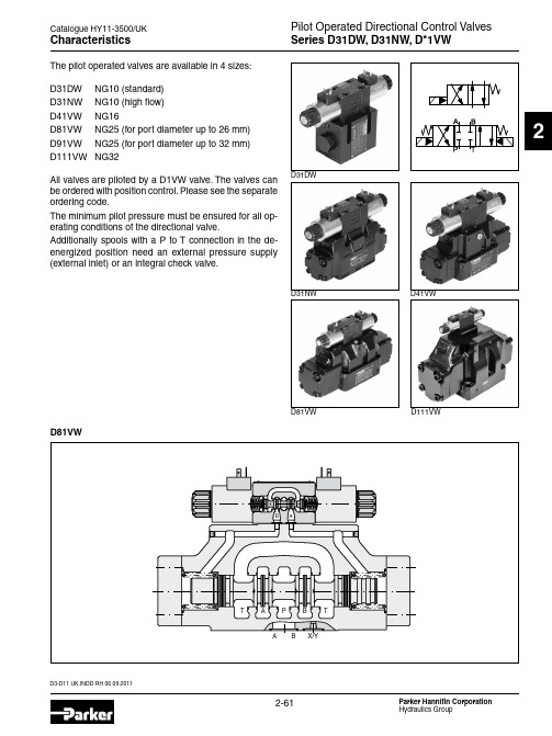
D3-D11 UK.INDD RH 06.09.2011Pilot Operated Directional Control Valves Series D31DW, D31NW, D*1VWCatalogue HY11-3500/UK2CharacteristicsThe pilot operated valves are available in 4 sizes:D31DW NG10 (standard)D31NW NG10 (high flow)D41VW NG16D81VW NG25 (for port diameter up to 26 mm)D91VW NG25 (for port diameter up to 32 mm)D111VWNG32All valves are piloted by a D1VW valve. The valves can be ordered with position control. Please see the separate ordering code.The minimum pilot pressure must be ensured for all op-erating conditions of the directional valve.Additionally spools with a P to T connection in the de-energized position need an external pressure supply (external inlet) or an integral check valve.D81VWD31DWD31NW D41VWD81VW D111VWPilot Operated Directional Control Valves Series D31DW, D31NW, D*1VWD3-D11 UK.INDD RH 06.09.2011Catalogue HY11-3500/UK2Ordering CodeSpoolSeriesSpool 1)2)Not for D31NW available 3)Not for D31NW and D111VW available 4)For D31NW and D111VW only pilot valve with detent availableD3-D11 UK.INDD RH 06.09.2011Pilot Operated Directional Control Valves Series D31DW, D31NW, D*1VWCatalogue HY11-3500/UK2Ordering CodeSolenoid options Solenoid voltageDesign series(not required for ordering)Pilot oil supply and drain optionsAcces-sories Further spool types and solenoid voltages on request.Explosion proof solenoids EEx me ll see catalogue HY11-3343. Download:/euro_hcd - see “Literature”Connector as per EN 175301-803,without plug(Please order plugseparately)Seals Code Seals N NBR VFPM Code Accessories omit Standard valve w/o accessories 3A Pilot choke, meter-out 3B Pilot choke, meter-in 3C Pilot with pressure reducing valve 3D 8)Stroke adjustment side B 3E 8)Stroke adjustment side A3F 8)Stroke adjustment side A and B 3R meter-out + pressure reducing valve 1Tmeter-in + pressure reducing valveCode Solenoid option omit Standard solenoid without options T without manual override 7)To be used in combination with rectifier plugs at 120VAC / 230VAC power sup-ply.Code Solenoid voltageK 12V =J 24V =U 7)98V =G 7)205V =Y 110V 50Hz / 120V 60Hz T230V 50Hz / 240V 60Hz5)N ot for D31DW, D91VW and D111VW available.6) N ot for spools 002, 007, 009, 014, 030, 031, 032, 054 available.Code Inlet Outlet 1Internal External 2External External 3 5)Integral check valve External 4 6)Internal Internal 5External Internal 6 5)Integral check valveInternal8)Only D31, D41, D81, D91 available.WCatalogue HY11-3500/UK2Ordering CodeWith inductive position controlPilot Operated Directional Control ValvesSeries D31DW, D*1VW Induct. Position ControlD3-D11 UK.INDD RH 06.09.2011D3-D11 UK.INDD RH 06.09.2011Catalogue HY11-3500/UK2Ordering Code6)The plug M12 x 1 for the position control is included. The monitor switch has to be located on the side to which the spool moves from the spring offset position. For 4/3-way valves two switches are used.Pilot oil supply and drain options4)To be used in combination with rectifier plugs at 120VAC / 230VAC power supply.Code Solenoid voltageK 12V =J 24V =U 4)98V =G 4)205V =2)N ot for D31DW, D91VW and D111VW available..3) N ot for spools 002, 007, 009, 014, 030 available.Code Inlet Outlet 1Internal External 2External External 3 2)Integral check valve External 4 3)Internal Internal 5 External Internal 6 2)Integral check valveInternalCode Solenoid option omit Standard solenoid without options T 5)without manual override5)For hydraulic presses according to the safety regulations EN 693, solenoid op-tion “T“ (without manual override) and accessories “I4N“, “I5N“ or “I6N“ (start position monitored) are required.Solenoid optionsSolenoid voltage Design series(not required for ordering)Acces-sories Connector as per EN 175301-803,without plug(Please order plugseparately.SealsCode Seals N NBR VFPM Code Spool positionPosition control I3NCEnd positionmonitored, side A and BI6N6)Start positionmonitored, side A and BI2N C, B, E, F (all spools)C, K, M (spool 9)End position monitored, side B I5N 6)Start position monitored, side B I1N C, H, K, M (all spools)C, E, F (spool 9)End position monitored, side A I4N 6)Start position monitored, side AAttentionThe adjustment of the position control is factory set and sealed.Replacement and repairs can only be undertaken by the manufacturer.WPilot Operated Directional Control ValvesSeries D31DW, D*1VW Induct. Position ControlPilot Operated Directional Control Valves Series D31DW, D31NW, D*1VWD3-D11 UK.INDD RH 06.09.2011Catalogue HY11-3500/UK2Technical DataWith electrical connections the protective conductor (PE W ) must be connected according to the relevant regulations.D3-D11 UK.INDD RH 06.09.2011Pilot Operated Directional Control Valves Series D31DW, D31NW, D*1VWCatalogue HY11-3500/UK2Electrical characteristics of position control M12x1Position ControlM12 pin assignment1 Us 18 (42V)2 Out B: normally open3 0V4 Out A. normally closed 5Earth groundDefinitionsStart position monitored:The valve is de-energized. The inductive switch gives a signal at the moment when the spool leaves the spring offset position (below 15% spool stroke).At the switching point the spool is located within the closed position. It is secured that only the flow paths of the offset position are granted.The switch can only be located on the opposite side of the solenoid for direct operated valves.Delivery includes plug M12 x 1 (see accessories, plug M12x1; order no.: 5004109).End position monitored:The inductive switch gives a signal before the end position is reached (above 85% spool stroke).Pilot Operated Directional Control Valves Series D31DW, D31NW, D*1VWD3-D11 UK.INDD RH 06.09.2011Catalogue HY11-3500/UK2Flow Curve DiagramsD31DW and D41VWThe flow curve diagram shows the flow versus pressure drop curves for all spool types. The relevant curve number for each spool type, operating position and flow direction is given in the table below.All characteristic curves measured with HLP46 at 50°C.D31NWD31DWD31NWD3-D11 UK.INDD RH 06.09.2011Pilot Operated Directional Control ValvesSeries D31DW, D31NW, D*1VWCatalogue HY11-3500/UK2Flow curve D31NWD81/D91VW and D111VWFlow curve D81VWFlow curve D41VW Flow Curves / Integral Check ValveIntegral check valve in the P portMounting an integral check valve in the P port is necessary to build up pilot pressure for valves with P to T connection and internal pilot oil supply. The pressure difference at the integral check valve (see performance curves) is to be added to all flow curves of the P-port of the main valve. Directional valves with an integral check valve are availablefor the series D31NW, D41VW and D81VW.All characteristic curves measured with HLP46 at 50°C.Pilot Operated Directional Control Valves Series D31DW, D31NW, D*1VWD3-D11 UK.INDD RH 06.09.2011Catalogue HY11-3500/UK2open,closedM6 DIN906M6 DIN906Slip-in orifice in pilot p-port(drawn offset)All orifice sizes for standard valvesPilot oil inlet (supply) and outlet (drain)Series D31DWSeries D41VWSeries Series Pilot Oil OptionsPilot Operated Directional Control Valves Series D31DW, D31NW, D*1VWCatalogue HY11-3500/UK2D31NWD31DWDimensionsThe space necessary to remove the plug per EN 175301-803, design type AF is at least 15 mm. The torque for the screw M3 of the plug has to be 0.5 to 0.6 Nm.* Please add for each sandwich plate +40mm (pressure reducing valve, choke valve meter-in/-out).* Please add for each sandwich plate +40mm (pressure reducing valve, choke valve meter-in/-out).Pilot Operated Directional Control Valves Series D31DW, D31NW, D*1VWCatalogue HY11-3500/UK2DimensionsThe space necessary to remove the plug per EN 175301-803, design type AF is at least 15 mm. The torque for the screw M3 of the plug has to be 0.5 to 0.6 Nm.D81VW, D91VWD41VW* Please add for each sandwich plate +40mm (pressure reducing valve, choke valve meter-in/-out).* Please add for each sandwich plate +40mm (pressure reducing valve, choke valve meter-in/-out).Pilot Operated Directional Control ValvesSeries D31DW, D31NW, D*1VW Catalogue HY11-3500/UK2 D111VWDimensionsThe space necessary to remove the plug as per EN 175301-803, design type AF is at least 15 mm.The torque for the screw M3 of the plug has to be 0.5 to 0.6 Nm.* Please add for each sandwich plate +40mm (pressure reducing valve, choke valve meter-in/-out).Catalogue HY11-3500/UKNotes。
Parker派克汉尼汾公司简介
Parker 为遍布世界五大洲的顾客提供满意的服务,涵盖范围广泛的工业项目,包括研发、 基础系统、生物加工、制药、发电、石油及天然气生产、石化加工和半导体制造等。
» 不间断气体供应系统
VERIFLO 产品
包括实验室、生产在线分析与医院
产品包括汇流排、减压阀、背压阀ห้องสมุดไป่ตู้隔膜 中央供气系统
阀、限流阀、压力安全阀、精微计量阀、
流量控制器等
技术咨询、购买、售后服务
辅助配件
管线装配工具、样品钢瓶、低压铜接头、 低压铜球阀、管夹
»
.
»
随着中国经济的飞速发展,Parker 对中国市场日益重视,1998 年 Parker 将大中华地区 总部设在上海,下属有上海、北京、广州、香港、台北 5 个销售办事处和专业技术服务中心, 并在上海外高桥保税区投资 5000 万美元建立了独资工厂及零部件保税仓库。
Parker 旗下的仪表管阀集团,主要涉及化工和石化加工、半导体制造、在线过程分析应 用、生命医疗和药品、纸桨和纸业、能源等领域,产品包括:仪表管接头,超高纯管接头和 密封件,球阀、旋塞阀、针阀和单向阀,隔膜阀和波纹管阀,PFA 和 PTFE 管接头,阀和泵, 调压阀和压力传感器,钢瓶接头,微型电磁阀,多阀组,快速连接头和软管产品等。
Instrumentation
派克-汉尼汾公司:
Parker Hannifin 是工业零部件及 其系统供应商和领导品牌,其总部 位于美国俄亥俄州克里福兰市。
Parker 是一家在 NYSE 上市(简称 PH)的美国公司,2007 财政年度销售 额达 120 亿美元。
Parker Hannifin Corporation CPH104P型号单向阀门说明说明书

Series CPH104PTechnical Information Performance CurvePressure Drop vs. Flow (Through cartridge only)SpecificationsMaximum Flow 30 LPM (8 GPM)Maximum 340 Bar (5000 PSI) - SteelInlet Pressure 210 Bar (3000 PSI) - Aluminum Leakage 5 drops/min. (1/3 cc/min.)at 340 Bar (5000 PSI)Pilot Ratio 3:1Operating Temp.-40°C to +93.3°C (Nitrile)Range (Ambient)(-40°F to +200°F)-31.7°C to +121.1°C (Fluorocarbon)(-25°F to +250°F)Cartridge Material All parts steel. All operating parts hardened steel.Body Material Steel or Aluminum Filtration ISO code 16/13,SAE Class 4 or better Mounting No RestrictionsCavityCommon Cavity No. C10-3General DescriptionThe CPH104P Series Single P .O. Check Valve will positively lock an actuator or permit flow to a portion of a circuit and not allow reverse flow until adequate pilot pressure is applied to the pilot port.OperationFree flow is permitted from the valve port (3) to the cylinder port (2). In the absence of adequate pilot pressure, the poppet remains seated preventingreverse flow. When adequate pilot pressure is applied at the pilot port (1), the pilot piston unseats the check poppet permitting reverse flow.Features•Hardened, precision ground parts for durability •Internal pilot pistonHydraulic Oil 135 SSU @ 100°F (28 cSt)6.95.52.84.11.4P r e s s u r e D r o p (P )∆Bar Flow (Q)15482LPMGPM0236308Pilot (1)Valve/Inlet (3)Series CPH104PDimensionsSeries CPH104POrdering InformationNOTE:If system pressure does not exceed 210 Bar (3000 PSI), aluminum bodies can be used.Higher pressures require steel bodies.Shipping Weight Cartridge Only .09 kg (0.2 lbs.)Cartridge in Body .86 kg (1.9 lbs.)。
派克比例阀价格表
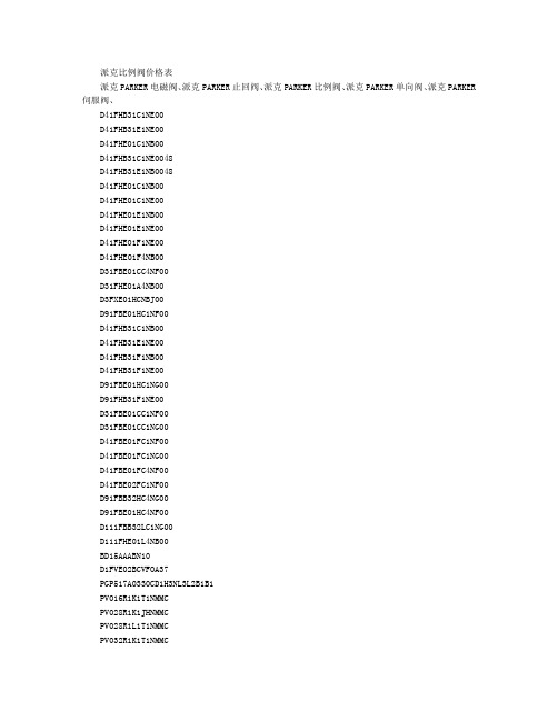
派克比例阀价格表派克PARKER电磁阀、派克PARKER止回阀、派克PARKER比例阀、派克PARKER单向阀、派克PARKER 伺服阀、D41FHB31C1NE00D41FHB31E1NE00D41FHE01C1NB00D41FHB31C1NE0048D41FHB31E1NB0048D41FHE01C1NB00D41FHE01C1NE00D41FHE01E1NB00D41FHE01E1NE00D41FHE01F1NE00D41FHE01F4NB00D31FBE01CC4NF00D31FHE01A4NB00D3FXE01HCNBJ00D91FBE01HC1NF00D41FHB31C1NB00D41FHB31E1NE00D41FHB31F1NB00D41FHB31F1NE00D91FBE01HC1NG00D91FHB31F1NE00D31FBE01CC1NF00D31FBE01CC1NG00D41FBE01FC1NF00D41FBE01FC1NG00D41FBE01FC4NF00D41FBE02FC1NF00D91FBB32HC4NG00D91FBE01HC4NF00D111FBB32LC1NG00D111FHE01L4NB00BD15AAABN10D1FVE02BCVFOA37PGP517A0330CD1H3NL3L2B1B1PV016R1K1T1NMMCPV028R1K1JHNMMCPV028R1L1T1NMMCPV032R1K1T1NMMCPV046R1K1T1NMMCPV046R1L1T1NMMCPV080R1K1T1NMMCPV092R1K1T1NMMCPV140R1K1T1NMR1PV180R1K1T1NMMCSSRB080E065004072TE0330CW260AAABBD15AAANB10PV046R1K1T1NMRDD41FTE01FC2NF0038TE0330CW260AAABPCD00A-400PV140R1K1T1NFR1RE10R25W4SN1XWMPVS25AZ140C1E015 N3571A1E010 N35870D1400520171D0059422 PWD00A-400VRD350-010-006 D31FTE02CC4NG00D31FTE01CC4NG00RE32E17T1SNG0D91FTE02HC4NG00D91FTE01HC4NF0040SD500A06V+H06SDVD3W004CNJWRDM2PT35KVG15D1VW011CNJWPRDM2PP16SVGCVH161PSVH101S20FV102SCV102PD31FHE02C1NB0040TE0330CW260AAABSD500A06V+H06SDVPVS08AZ140C2R4R03-535-11B1D3W1CNJP30D31FHE02C1NB00404D01-3208-0302-B1-GOQBD15AAABN10PV016R9K1T1NMMCK0188R4V03-533-10-P2GOPA1DWEE527P20ELAFPV023R1K1T1NMM1EPP34CC1I60010PV140R1K1TINFR1BD15AAABN10派克PARKER Herl T5F-CO2 DN50 PV140R1K1TINFR1PV023R1K1T1NMR1D3W1CNJP30PS100-POHO DBD1VW20DVJW75D41VW004C1NJWFM2DDSVZDV-ABS-02-5-S0-D1V-C1DB101E320S9900D91FWB32HC4NLW028D1VW020DNJWD41VW020D1NJWR4V1053511A1D1FVE02BCF0A37CPOM6AAVDK-D1VW75-10D3W4CNJWD41FTE01FC1NF0040D3W004CVJWCPOM4AAHTVC032BN12VPRDM2PP16SVGD3W20BNJWD1VW020HVJWD81VW020D1VJWCPOM6DDVC063AA20VSVLB1086E32SD3W4CNJWPVCRER1N1PVACPPCMN35R4V03-533-10-P2GOPA1PRDM2PP06SVGPRDM2PP16KVG15D1VW034CNJWD3W001CNTWPRDM2PT35KVGD31FHE02C1NBOOD1VW020BNJW91FM3DDSV51PD140PS02SRS5AC00S100D3W004CNJWD3W020BNJW42PD100PS02SRS5AC10S300公司主要做欧美品牌,我们在德国、美国有公司,可以采购欧洲任何国家的品牌,比如德国的优势品牌有:德国宝德BURKERT,德国DEMAG德马格、德国HAWE哈威,德国REXROTH力士乐,德国HYDAC贺德克,德国PILZ皮尔兹继电器,德国FESTO费斯托,德国IFM易福门传感器,德国E+H恩德斯豪斯,德国海德汉HEIDENHAIN,德国P+F倍加福传感器,德国施克SICK,德国TURCK图尔克,德国HIRSCHMANN赫斯曼工业交换机。
我们先对派克PARKER电磁阀有个初步的认识,电磁阀是由电
我们先对派克PARKER电磁阀有个初步的认识,电磁阀是由电磁线圈和磁芯组成,是包含一个或几个孔的阀体。
当线圈通电或断电时,磁芯的运转将导致流体通过阀体或被切断,以达到改变流体方向的目的。
电磁阀的电磁部件由固定铁芯、动铁芯、线圈等部件组成;阀体部分由滑阀芯、滑阀套、弹簧底座等组成。
电磁线圈被直接安装在阀体上,阀体被封闭在密封管中,构成一个简洁、紧凑的组合。
我们在生产中常用的电磁阀有二位三通、二位四通、二位五通等。
这里先说说二位的含义:对于电磁阀来说就是带电和失电,对于所控制的阀门来说就是开和关。
它由阀体、阀罩、电磁组件、弹簧及密封结构等部件组成,动铁芯底部的密封块借助弹簧的压力将阀体进气口关闭。
通电后,电磁铁吸合,动铁芯上部带弹簧的密封块把排气口关闭,气流从进气口进入膜头,起到控制作用。
当失电时,电磁力消失,动铁芯在弹簧力作用下离开固定铁芯,向下移动,将排气口打开,堵住进气口,膜头气流经排气口排出,膜片恢复原来位置。
在我们的制氧设备中,在透平膨胀机进口薄膜调节阀的紧急切断等处有应用。
对派克PARKER电磁阀在应用中的一点认识:电磁阀在我们的生产中应用十分广泛,我们在对生产的维护中一定遇见过不少有关电磁阀的问题,也处理过各种各样的故障,大家也一定积累了不少有关电磁阀故障处理的经验,而我在维护中处理电磁阀故障相对别的仪控故障相对较少,现在我就这个问题一起和大家讨论,渴望从大家那里学习更多的经验,共同提高。
派克PARKER电磁阀在液路系统中用来实现液路的通断或液流方向的改变,它一般具有一个可以在线圈电磁力驱动下滑动的阀芯,阀芯在不同的位置时,电磁阀的通路也就不同。
阀芯的工作位置有几个,该电磁阀就叫几位电磁阀:阀体上的接口,也就是电磁阀的通路数,有几个通路口,该电磁阀就叫几通电磁阀。
电磁阀安装后,一般所有接口都应该是连接好了的,所谓工作位置指的是阀芯的位置。
阀芯在线圈不通电时处在甲位置,在线圈通电时处在乙位置,阀芯在不同位置时,对各接口起到或接通或封闭的作用。
派克换向阀样本
技术参数 概况
结构形式 公称尺寸 接口 安装位置 环境温度 重量:单电磁铁阀 双电磁铁阀 紧固螺栓 滑阀式换向阀 DIN NG6 / CETOP 03 / NFPA D03 DIN 24340 A6 / ISO 4401 / CETOP RP 121-H / NFPA D03 任意,优先考虑水平位置 -25°C...+50°C 1.5 kg 2.1 kg 4 个 DIN 912 M5x30-12.9; 扭矩 8.1 Nm ± 10%; 订货代号 BK 375 液压油依照 DIN 51524 / 51525 标准 -25°C至 + 70°C 2.8 至 400 mm2/s (2.8 至 400 cSt) 350 bar 标准的: 105 bar 代号 H: 210 bar 每个控制边至 10 ml/min 取决于阀芯 80 l/min NAS 1638 7-9级, 达到 β10 > 75 100% ED; 注意: 线圈温度可到150OC IP 65 DIN 40050 标准(在插和装情况下) 吸持 代号 功率 30 W 30 W 8W 30 W 30 W 64 VA / 59 VA 68 VA / 62 VA 直流 32 ms / 40 ms 15.000 次/小时 插头依照 DIN 43650 标准, 可选择 AF/PG11结构的插座, 带引线的接线盒 , 也可选择插入式插头 插头 M12x1 (仅用于 8 W) 电流 2.5 A 1.25 A 0.33A 0.31 A 0.15 A 0.58 A / 0.49 A 0.31 A / 0.26 A 功率 231 VA / 240 VA 231 VA / 240 VA
代号 无 5
说明 标准的阀 不带附件 在接线盒里的指示灯 和接线端子 在接线盒里的插入 式插头外壳 3- 针= 单个电磁铁 5- 针= 双电磁铁 A 端终点位置监控 B 端终点位置监控 选择 5 和6 组合 在一起 A 端初始位置监控
Parker Hannifin 3-Way和4-Way阀门操作说明说明书
FLUID CONTROL DIVISIONParker Hannifin Corporation95 Edgewood AvenueNew Britain, CT 06051Telephone (860) 827-2300IOM HN01Fax (860) 827-2384(Rev 0812)Installation, Operating & Maintenance Instructions3-Way and 4-Way, Pilot Operated, Sealed Spool Solenoid Valves1/4" NPT & 1/2" NPTValve Types: U331N03, U331N04, U341N03, U341N04, U341N05,U342N03, U347N03GENERAL SAFETY INSTRUCTIONS BEFORE INSTALLATIONFAILURE OR IMPROPER SELECTION OR IMPROPER USE OF THE PRODUCTS AND/OR SYSTEMS DESCRIBED HEREIN OR RELATED ITEMS CAN CAUSE DEATH, PERSONAL INJURY AND PROPERTY DAMAGE.Both the conduit coil and hazardous coil contain a green “grounding” wire that must be secured to a proper ground location. DO NOT cut off the green ground wire. Doing so could negate a proper ground path and leave the valve assembly unprotected or “hot”.This document and other information from Parker Hannifin Corporation, its subsidiaries and authorized distributors provide product and/or system options for further investigation by users having technical expertise. It is important that you analyze all aspects of your application, including consequences of any failure, and review the information concerning the product or system in the current product catalog. Due to the variety of operating conditions and applications for these products or systems, the user, through its own analysis and testing, is solely responsible for making the final selection of the products and systems and assuring that all performance, safety and warning requirements of the application are met. Usage of the device in a manner that is contrary to these Operating Instructions or the application conditions and specification providedin the Catalog is improper and will void your warranty.The products described herein, including without limitation, product features, specifications, designs, availability and pricing, are subject to change by Parker Hannifin Corporation and its subsidiaries at any time without notice.Carefully read installation, operation and maintenance procedures prior to installing or servicing valve.Do not use valve as a safety shut-off valve when making repairs.Do not install a valve or attempt to repair a valve before depressurizing system down to atmospheric pressure and removing electrical voltage.Care must be taken to ensure the proper use of the valve and that the valve materials selected are suitable for the media being handled. Parker assumes no liability for damage caused by improper material selection in the case of corrosion from aggressive media.Caution: Do not, at any time, make any alteration or modifications to any valve without the express and written approval of Parker’s Fluid Control Division.DescriptionThese valves are pilot operated 2-position, 4 ported 3-way or 5 ported 4-way, and 3-position 5 ported 4-way, directional control, solenoid models. They are offered in anodized aluminum body construction. Valves may be ordered with either DIN or Conduit NEMA 2, 4, 4X integrated coils for ordinary locations or NEMA 7 and 9 for hazardous locations:Applicable StandardsFM CSADivisions I; Class I, Groups A, B, C, D Divisions I; Class I, Groups A, B, C, DDivisions II; Class I, Groups E, F, and G Divisions II; Class I, Groups E, F, and GClass 1, Zone 1, AEx m II T4 Class 1, Zone 1, Ex m II T4The spool valves comprise a standard locking manual override providing operation without electrical supply.The spool valves are offered with the following standard features:-In line pilot for a low profile-22mm DIN pilot for direct mounting in non-explosive environments.-Both Conduit and Hazardous pilots for NEMA rated and explosive environments. Mounting plate required for NEMA rated coils.-High Nominal Flow-Cv 1.2 for 1/4” valves or 1250Nl/mn-Cv 3.0 for 1/2” valves or 3000Nl/mn-Standard Fluid temperature 14°F (-10°C) to 122°F (50°C)-Single Solenoid electrically operated, combined spring & pneumatic return (U331 & U341 series)-Dual Solenoid (Bistable) electrically operated, with neutral position return closed (U342 series)-Dual Solenoid (Bistable) electrically operated, air-solenoid return (U347 series)Principles of Operation – Connection of the NAMUR spool valve3-Way ValvesThe valve is piped to a single acting spring return cylinder as follows: Supply air pressure is applied at the inlet port 1. When de-energized, the valve inlet port 1 is closed and valve cylinder port 2 is open to the valve exhaust port 3. The cylinder is in the retracted state.When the coil is energized, pressure is applied from the valve inlet port 1 to the valve cylinder port 2 forcing the cylinder open and exhausting air behind the piston to the valve exhaust port 3. The cylinder is in the extended state.4-Way ValvesThe valve is piped to a double acting cylinder as follows: Supply air pressure is applied at the valve inlet port 1. Valve port 2 is open to one port of the cylinder while valve port 4 is open to the other port of the cylinder. The solenoid valve functions in such a way that pressure is applied to either side of the piston in the cylinder, and exhausted out of the opposite side of the pressurized cylinder.When de-energized, the supply air pressure port 1 is open to the valve port 2, valve port 4 is open to valve exhaust port 5, and valve exhaust port 3 is isolated by seals on the spool. The pilot valve orifice is sealed by the insert in the plunger. The pilot valve exhaust port is open to the valve piston assembly and atmosphere.When energized, the valve inlet port 1 is open to port 4, as well as between valve port 2 and valve exhaust port 3. The spool and seals seal valve exhaust port 5. This allows pressure to be applied to other side of the piston in the cylinder, causing the piston to move, and exhaust the fluid on the other side of the piston of the cylinder into port 2, through the valve and out of valve exhaust port 3.Manual OverridesManual override - The unit is shipped with a latching manual override. For a latching override, apply force to the slotted screw component, turn clockwise to lock. To unlock, turn counterclockwise.Fluid CodesListed below are the common fluid codes The codes for the approved fluids for use with each valve are printed on the outside of the individual packaging.CODE FLUIDA- Air or non-toxic, nonflammable gasesFor the maximum fluid temperatures, as well as valve ambient temperature limitations, check the valve part number on the nameplate and refer to the catalog.Installation InstructionsPrior to installing the solenoid valve, depressurize the pipes and clean them internally to avoid particles entering theMounting position and pressure limits:Valve with DIN Coil:Mount the valve directly on the actuator with the (2) M5 thread screws provided for the 1/4" valve and with the (2) M6 thread screws for the 1/2" valve. Torque to 35 to 45 in-lbs (4 to 5 Nm). Make sure the O-rings and locating pin are assembled to the bottom of the valve prior to mounting the valve for correct positioning on the actuator. Do not use the sleeve or enclosure as a lever when applying torque.Valve with Conduit or Hazardous Coil: (see next paragraph for valve model U341N05 only)The conduit and hazardous coils require the use of a mounting plate kit due to the increased coil width. The mounting plate kit consists of the aluminum mounting/spacer plate, 2 O-rings and 2 longer screws. The valve model number U341N05 containing the 3/2, 5/2 conversion plate does not require a separate mounting kit (see next paragraph). Make sure the O-rings are assembled to the bottom of the valve before positioning the valve over the mounting/spacer plate. Make sure that the O-rings and the locating pin are assembled to the bottom of the mounting/spacer plate prior to mounting the valve onto the actuator. Use the 2 longer screws to mount the valve to the actuator. Torque to 35 to 45 in-lbs (4 to 5 Nm). Do not use the sleeve or enclosure as a lever when applying torque.Valve model U341N05 with conversion plate:With the U341N05 valve, the 3/2, 5/2 conversion plate also functions as the mounting/spacer plate for the conduit and hazardous coils. Make sure that the gasket surface with the function indicator tab is assembled toward the bottom of the valve body. The indicator tab will point toward the schematic on the top of the valve body indicating the valve function. To change the valve function, rotate the conversion plate 180 degrees keeping the gasket face toward the vale body. The O-rings and the locating pin are assembled to the bottom of the conversion plate prior to mounting the valve onto the actuator. Use the 2 of the included screws to mount the valve to the actuator. Torque to 35 to 45 in-lbs (4 to 5 Nm). Do not use the sleeve or enclosure as a lever when applying torque.The valves are multi-poised and will perform properly when mounted in any position. However, for optimum life and performance, the valves should be mounted with the spool in the vertical position to minimize wear and reduce the possibility of foreign matter accumulating inside the sleeve and spool area.Line pressure must conform to nameplate rating.Valve Piping: Correctly support and align pipes to prevent mechanical strain on the valve. Connect line pressure to the inlet port. Use of tape sealant, thread compound or sealants is permissible, but should be applied sparingly to male pipe threads only. To avoid damage to the equipment, DO NOT OVERTIGHTEN pipe connections.Media filtration: Normally, filtration is not required, but dirt or foreign material in the media may cause excessive leakage, wear, or in exceptional cases, malfunction. The valves do include a 40 micron internal pilot filter to help prevent clogging of the pilot orifice. If additional filtration is used, install the filter on the inlet side as close to the valve as possible. Clean periodically depending on service conditions.Lubrication: Lubrication is not required.ELECTRICAL CONNECTIONSGeneral Recommendations and Safety Precautions- Electrical connection must be made by qualified personnel using standard electrical practices in compliance with local authorities and the National Electrical Code.- Depending on the voltage, electrical components must be grounded according to local standards and regulations- Most valves are designed for continuous duty. To prevent the risk of personal injury, do not touch the solenoid operator which can become hot under normal operating conditions.-The solenoid coil must be assembled to the valve sleeve operator for proper valve operation. Failure to assemble the coil to the valve before applying system voltage will permanently damage the coil within a short period of time.- Electrical supply must conform to nameplate rating.Hazardous Location Coil WARNING: Valves to be installed in Hazardous Locations, must be outfitted with Hazardous Location coils only. Verify nameplate data and coil part number before installing the valve.A surge protector corresponding to the coil’s rated current or a motor safety switch with instantenous short circuit or thermal cutout (set at rated current) has to be pre-connected for each solenoid coil as a short circuit cutout. The surge protector may be positioned in the respective power supply unit or it must be pre-connected separately.W ARNING:Turn off electrical power before connecting the valve to the power source.If the coil assembly is located in an inconvenient orientation, it may be reoriented to facilitate installation. Loosen coil assembly nut, rotate coil assembly in 45° increments to desired position, and then retighten the nut with an input torque of 4.0 to 5.0 in-lbs. [0,5 Nm].DIN Coil (ND1x) and various cable option terminations: Electrical connection is made with detachable DIN 43650 B plug connector for cable dia. 6-8mm (Pg9), rotatable by 180° increments (3 pins: 2 + earth ground pin). Loosen cable screw and remove plastic housing from DIN coil. Do not remove the gasket from the DIN spades on the coil. Separate the plastic block from the housing with a small screwdriver to expose the elecctrical terminations. Feed the lead wires through the conduit hub and attach them to the appropriate screw terminal. For electrical connection within the terminal box, use field wire that is rated for 90o C or greater. Snap the plastic block back into place inside the metal enclosure. Replace the cover and hand-tighten the cover screws. Place the gasket over the DIN spades on the coil and press the terminal box and coil together. Secure the terminal box to the coil using the mounting screw provided.Slide one o-ring over and down the sleeve assembly until the o-ring rests on the valve body., Slide the DIN coil over the valve sleeve. Affix nut to sleeve and tighten between 4.0 to 5.0 in-lbs. [0,5 Nm] torque.Conduit Coil (NC1x) with 1/2” NPT connection: Conduit coils meeting NEMA 2, 4, 4X integrated coils for ordinary locations. Use suitable electrical cabling and conduit materials and components meeting applicable NEMA recommendations.Hazardous Coil (NH1x) with 1/2” NPT connection: Hazardous coils meeting NEMA 7, and 9: Divisions I and II; Class I, Groups A, B, C, and D; Class II, Groups E, F, and G. Use suitable electrical cabling and conduit materials and components meeting applicable NEMA recommendations.Coil/enclosure temperature: Standard valves are supplied with coils designed for continuous duty service. Normal free space must be provided for proper ventilation. When the coil is energized continuously for long periods of time, the coil assembly will become hot. The coil is designed to operate permanently under these conditions. Any excessive heating will be indicated by smoking and/or odor of burning coil insulation.For the maximum valve ambient conditions, as well as the fluid temperatures, check the valve part number on the nameplate and refer to the catalog to determine the maximum temperatures.MAINTENANCEPrior any maintenance work, switch off power supply, depressurise and vent the valve to prevent the risk of personal∙Preventive maintenanceValve should be exercised (cycled from de-energized to energized position several times) if stored in inventory or if inactive for a lengthy period of time (more than a month).Avoid obstruction of exhaust port when it is not connected or protect it with a cap.∙CleaningMaintenance of the valve depends on the operating conditions. They must be cleaned at regular intervals. Cleaning must be done when a slowing down of the cycle, a leakage or an abnormal noise is noticed. The components must be checked for excessive wear.Note: Depending on service conditions, filtration, and lubrication, it may be required to periodically clean and/or replace worn components.C AUTION:Do not expose plastic or elastomeric materials to any type of commercial cleaning fluid. Parts should be cleaned with a mild soap and water solution.Monostable in line Miniature pilot Bistable Miniature pilot O-ring 10O-ring 9Screws 8Under Seat Flow Path 7Pin6“Bug”cap 5Operator Sleeve 4Manual Override 3O-ring11Pilot Top Plate 2Pilot Body 1DescriptionItemPilot ValveCross Section ViewConversion PlateHazardous or Conduit Coil U331N03, U331N04 13551331524 3154 2Trouble ShootingSymptom Procedure 1. Valve fails to operate or is sluggish. 1. Check electrical supply with voltmeter. Voltage must agreewith coil rating.2. Check coil with ohmmeter for shorted or open coil.3. Make sure that pressure complies with pressure ratingmarked on valve. Pressure must not be less than minimumoperating pressure.4. Inspect for contamination in ports. Remove debris if found.Check filter in main body, clean or replace if necessary.5. Verify that the sleeve assembly and plunger spring are notdamaged.* Remove the 4 screws and gently lift off the pilot sectionof the valve. Take care not to lose the o-rings andinternal components.* Remove the top plate. Lift out and inspect the sleeve,plunger, rubber disk and spring for debris or damage.Replace sleeve assembly, top plate and 4 screws.* Make sure the manual override stem is located on theported side of the valve body.2. External leakage at sleeve flange to body joint or pilot section to main body joint. 1. Check the 4 screws are tight but do not apply excessive forceto damage the plastic plate.2. If leakage persists, remove sleeve and check flange ando-ring seals for damage. Refer to step 5 above for disassembly.。
派克.丹尼逊单向阀直控式先导式法兰式C4V C5V C5P系列
L/min
bar
C4V03 3/8” 180
350
z
z
z
C4V06 ¾” 360
350
z
z
z
C4V10 1 ¼” 600
350
z
z
z
7-2
m C5V06 ¾” 90
420
设 级 co C5V
• 法蘭式 • 直控式
C5V08 1” 200
420
• SAE-61 & 62
C5V10 1 ¼” 400
420
C5V08-321-B1........................................ 安裝型式
限 商 420 bar, SAE-61
3
420 bar, SAE-62
6
有 销 C5V08-321-B1................................................閥體
sae4600750x1y1直動式派克丹尼逊一级分销商直動式先導式75北京威士乐机电设备有限公司c5vc5p安裝形式l1法??栓x4組合?型l1美制公制擰緊?矩尺寸c5v
單向閥
7. 單向閥
司
公
限 系列
可供類型
最大流量 最大壓力
型號 尺寸
板式
管式
插裝式
SAE 法蘭 安裝
頁次
备有 分销商 C4V
• 直控式 • 先導式
直動式 1 : ................................... 例 : C5P08-581-2-A1
备 分 1. C5P06-581-2-A1 ........................................ 系列號