Arium611超纯水机中文手册
sartorius arium 611vf说明书
Installation and Operation Manualarium 611VFWater Purification System85030-513-682About This Manual Safety Information 3Intended Usage 4Product Description 5arium Systems5Control Panel and Display 6Unpacking and Installation 8Unpacking8Display|Dispenser Unit Installation 8Ultrafilter Installation 10Bench Mounting 11Wall Mounting11Water Inlet Connection 12Reject Water Connection12Initial Operation 13Cartridge Installation 13System Settings14Setting the Date and Time 14Measurement Units 14Set Point 15Language15Initial Flush and Sanitization 16Flushing and Purging Air from the Cartridge Packs 16System Sanitization 16 Ultrafilter Flush17Reset UV Timer Prior to Initial Operation 17Final Filter Installation 17Further Options 18Print Data18Pump Protection18Time|Volume Dispense 19Set Cell Constant20Calibration of the System 21Start Up|Operation 22Normal Operation Mode 22Dispensing Product Water 22Standby Mode22System Inactive Mode 23Maintenance and Servicing 24Sanitization24Cartridge Replacement 25 Ultrafilter Replacement 26Replacing the Final Filter 26Cell Cleaning27UV Bulb Replacement 28Activate the UV Timer 29Fuse Replacement30Appendix31Troubleshooting Guide 31Specifications32Accessories and Replacement Parts33This manual instructs you on how to prepare and operate the arium 611VF water purification system.Sartorius has designed the arium 611 water purification system for reliability, economy and safe operation. To ensure this, you must read this instruction manual carefully before attempting to operate the system. The manual will give you important instructions that will help you avoid potential hazards and ensure the reliability of the arium 611VF.Please read the Safety Information on page 3.If you have any questions about the correct use of arium 611VF, please contact us at the address below or your local Sartorius office:Sartorius AGLife Science Business Unit - Lab Division Weender Landstrasse 94–10837075 Goettingen Phone +49.551.308.0Fax +49.5 51.308.3289Table of ContentsPlease read the following safety information thoroughly and follow the instructions exactly. This information is designed to ensure your own safety and will prevent damaging the arium 611VF unit.The following symbols are used in this manual:Warning!Warnings alert you to a possibility of personal injury or property damage.Caution!Caution signs alert you to a possibility of damage to the equipment.NoteNotes alert you to pertinent facts and conditions that are important for economic operation of the equipment.Warning!Danger of personal injury!Servicing and repairs may only be performed by trained and qualified personnel.Warning!Severe electrical shock hazard or danger of electrocution!–Use a properly grounded electrical outlet of correct voltage and current handling capacity (100 to 240 V ~, 50/60 Hz) to plug in the arium 611VF unit.–Do not locate arium 611VF on top of electrical equipment. Routine maintenance of this unit may involve water spillage and subse-quent electrical shock hazard if improperly located.–Remove the plug from the electrical outlet prior to maintenance and servicing of arium 611VF.3Safety InformationWarning!Danger of fire or explosion!–Do not use in the presence of flammable or combustible materi-als; fire or explosion may result.This device contains components which may ignite such materials.–The arium 611VF is to be used with water feeds only. Sanitizing|cleaning agents should only be used according to the instructions in this manual.Warning!Danger of injury to eyes and skin!–Avoid splashing sanitants or disinfecting solutions on clothing or skin.–Ensure all tubing connections are tight to avoid chemical leakage. –Turn off feed water and push the draw-off lever to the right to depressurize system prior tochanging cartridge packs, sanitizing or performing any service on the 611 system.–Allow a defective UV bulb to cool off before removing it.–Carefully follow the manufacturer’s safety instructions on labels of chemical containers and filter cartridges.Caution!Danger of irreversibly damaging arium 611VF components!Be sure to replace defective fuses with those of the same type and rating.When installing a new UV bulb, do not touch the bulb with your bare hands.Finger prints may damage the bulb.!!!!!Intended UsageThe arium 611VF water purificationsystem is designed exclusively toprovide reagent-grade water for thelaboratory from water pretreated bydistillation, deionization or reverseosmosis. To ensure that this unitworks properly, use only the filtermedia and other auxiliary mediathat are listed in this manual. Usingthis system for any other purposeshall be considered improper usage.–arium 611VF may only be operated by trained personnel.–Operate arium 611VF only usingoriginal accessories or replacementparts. If you modify this waterpurification system on your ownwithout consulting Sartorius, theperformance and operating safetyof the system are no longer guaran-teed, thus constituting a safetyhazard for the operator.–Please take all pertinent precautions to prevent accidents and observethe generally valid technical andoccupational safety rules andregulations of your country.–Use only Sartorius-listed materials (such cartridges, connectors,gaskets, tools and sanitizing anddisinfecting agents).4arium SystemsThe Sartorius arium 611VF is a water purification system designed to provide pyrogen-free, low TOC reagent grade water that exceeds ASTM Type I and NCCLS Type I standards. The system uses a deionization process with mixed bed resins and activated carbon combined with UV oxidation, ultra-filtration and a 0.2-micron final filter to produce laboratory reagent grade water. The 611VF system is capable of producing pyrogen-free (< 0.001 EU/ml), low TOC (< 1 ppb)water with a resistivity of up to 18.2 MegOhms + cm. Water resistivity is continuously sensed by a resistivity cell and displayed on a digital display.Item No.Description1Left and right door of arium 611VF2Product water outlet with 0.2-micron filter and bell assembly3Display and control panel 4Recessed grip for opening the right door 5Draw-off lever for opening and closing the outlet valve(shown in open position)6Outlet for a remote dis-play|dispenser unit, TOC instrument or a dispenser 715-pin D-sub port for connecting a remote display|dispenser unit 8Outlet for time|volume dispense9Reject water outlet 10Fuse drawer11Main power switch 12Power cord receptacle 139-pin D-sub port for connecting a printer 14Connector for pumpinterlock that prevents the pump from running dry 15Feed water inlet5Product DescriptionFront viewSide view, left321101112131415456987Control Panel and Display Operate arium 611VF using the control panel that incorporates four function keys and two control keys for the cursor.STANDBY KeyPress the Standby key to placethe unit into Standby Mode. In this mode the water in the system is recirculated for 15 minutesper hour.OPERATE|STOP KeyPress the OPERATE|STOP key to activate or deactivate the unit. During Normal Operation the system will recirculate. When the system is stopped the pump turns off and water will not recirculate.MENU KeyThis key provides access to system options and menus.Cursor keysThese two cursor control keys are used to select individual menu items of the different menus. The Y key moves the cursor one line up, the y key one line down.ENTER KeyUse this key to select a menuitem you have highlighted with the cursor.Display–During Normal Operation the display will show the waterquality reading – according tothe pre-selected measurementunit options:(M O+cm or µS/cm) The letter “C” indicates that thewater quality measurement isautomatically compensatedto 25°C.–When the system is in Standby Mode the display will show“Standby”. The UV bulb will turnon periodically to make certain the TOC is kept at an acceptable level.An automatic flush will take placeevery 24 hours. When the systemis flushing the display shows thefollowing:–The display will show the followingwhen the system is stopped:6Control panel and display of arium 611VFFlow chart of arium 611VF7UnpackingRemove arium 611VF from its packaging. You will find the accessories inside the arium housing and in the top cover of the packing. The equipment supplied includes the following parts:Display|Dispenser Unit Installation The Display|Dispenser unit hasbeen designed to mount in 3 ways: At the top of the right door forbench systems, at the bottom of the right door for wall mount systemsor in a remote location from thesystem (additional kit required).To install:•If necessary, remove the rubber cover mounted at the bottom ofthe right door (for wall mounting).•Route the supply cables through the large opening of the right door(top or bottom) and the two watertubes from the outside through the small opening.•Use the 4 screws and washers provided to mount the Display|Dispenser Unit to the door byrouting the screws from inside thedoor through the holes in the doorto the outside and screw to theassembly.•Route the water tubing through the4 holes inside the door and connectto the color coded connectors.Follow the course of dotted linesin the figure:Positions (1) and (3): data andpower cablesPositions (2) and (4): water tubes •Put rubber cover into the remaining hole (top or bottom) in the door.8Unpacking and InstallationPart Description Number arium 611VF 1 Dispenser unit with display1 Screws and washers for the Display|Dispenser unit4Blue cover with manufacturer's label (VF)1Blue cover with model name of arium (for dispenser unit)1 Ultrafilter cartridge1 Reject water tubing 1 Tubing adapter for inlet water (1”, English and 4”, NPT)2 Tube for inlet water with quick disconnect insert1 Adapter with O-ring for cartridge pack1End cap for the sanitization syringe adapter1 Sanitization syringe 1Wall mounting bracket1 Power cord1 Installation and operation manual 1 Timed Dispense Tube, PE4inch OD X 8 feet1 Tubing adapter, 4 inch OD tube to 4NPT1NoteThe cartridge packs are suppliedseparately. They are not includedin the arium system packaging.12Mounting the upper display|dispenser unit34Mounting the lower display|dispenser unit9Ultrafilter InstallationCaution!Danger of irreversibly damagingarium 611VF components and thefilter cartridges! Tighten all unionnuts made of plastic by hand.Do not use a wrench or pliers.Before starting up arium 611VF,you need to install the ultrafiltermodule in the housing cover.Proceed as follows:•Make sure to unplug the power cord from the electrical outlet(“O”).•Open both doors of the unit.•Remove ultrafilter from packaging and remove protective covers fromfittings.•Connect the tubing connectors to the ultrafilter module as shown inthe Figure:(1): green connector for feedwater - Bottom(2): blue connector for productwater - Upper left(3): red connector for rejectwater - Top•Push in the ultrafilter module all the way into the holders so thatthe connector fitting on the sideis facing left.•Close both doors.10Attach the three tubing connectors to the ultrafilter module123Bench Mounting Warning!Severe electrical shock hazard or danger of electrocution!Do not place arium 611VF on top of electrical equipment. Water may spill when using the system.Warning!Danger of fire or explosion!Do not use in the presence of flammable or combustible materi-als; fire or explosion may result.The device contains components which may ignite such materials.•Place the arium 611VF on a flat surface.•Ensure that feed water and a 100-240 V electric socket are accessible.NoteThe outlet of a gravity feed storage reservoir must be at least 10 cm higher than the inlet of the arium 611VF.Wall MountingCaution!Wall composition, condition and construction, as well as fastener type must be considered when mounting this unit. The mounting surface and fasteners selected must be capable of supporting a minimum of 25 kg. Inadequate support and|or fasteners may result in injury to the operator and|or damage to the equipment.A wall bracket (2) is included in the shipment to enable you to attach the system securely to the wall so that it occupies a minimum amount of space. A clear wall area of 63 +63 cm is required to mount the arium system. Two sturdykeyhole drill holes (1) are located at the top of the back of the housing enabling you to hang the unit on the two pins (5) on the wall e the predrilled holes in the bracket to fasten the bracket to the wall. The lower metal profile (6)on the arium housing functions as a spacer.•Ensure that water, a 100 - 240 V electric socket and an atmospheri-cally vented drain are accessible.•Fasten the bracket to the wall with suitable screws and dowels.•Lower the keyhole drill holes of the arium 611VF onto the two pins on the wall bracket.•Tighten the screw (3) of the metal support (4) on the right side of the bracket with a screwdriver until the metal support rests against the arium housing.!!!123456Lower the arium housing onto the wall-mounting bracketWater Inlet Connection Feed water is supplied to the system through this inlet (1). The arium system is supplied with two water supply adapters – one with 1” British thread and one with 4”-NPT.Caution!Do not draw water from the top of an open container or carboy to supply water to the 611 system.Damage to the system may result.NoteWe recommend that a customer supplied shutoff valve be installed in your feed water line.If a gravity tank is used to supply feed water to the 611 system, the feed water tube must be connected to the bottom of the tank with a ridged or hard plumbed connection.The connection at the bottom of the gravity must be level with, or preferably, slightly above the inlet water connection of the 611system.•Connect the free end of the tube to the appropriate water supply adapter. Push the tube all the way into the adapter to seat it properly (approx. 20 mm).•Install the tubing adapter onto your feed water source.•Cartridges must be installed prior to supplying feed water to the system. See cartridge installation instructions.•Insert the other end with a quick disconnect insert into the system’s counter coupling (1) until it audibly clicks into place.Reject Water Connection The reject water is discarded through this connection (2). The reject water tubing has a 4-inch O.D.Push the tube all the way (approx.20 mm) into the reject water connector (2)) to seat it properly.Direct the other end of the reject tubing to an atmospheric drain.NoteEnsure there are no kinks in the tubing and that it proceeds in a downward plane.Connector for feed water tubingConnector for reject water tubing2Cartridge Installation •Open both doors of the system.•Remove both cartridge packs from their packaging.One cartridge pack has a label with a blue dot and the number 1, the other cartridge has a red dot and the number 2. In the housing to the lower left side you will find a blue labeled cartridge adaptor, on the lower right side a red cartridge adaptor.•Remove the red plugs from the top of the cartridge pack and push the blue adapter onto the cartridge pack with the blue dot. Press vigorously. Be sure the label with the blue dot faces you. The adapter displays “front”.Two screws each are seated in the cartridge cover. The two screw heads must rise from the drillings of the safe guard slides with the upper ring of the spacers. •Push both safe guard slides all the way under the upper ring of the spacers, as shown in the figure opposite.•Place the cartridge pack with the blue dot left into the housing and push until properly seated. Be sure the label faces you.•Proceed with the cartridge pack with the red dot in the same manner on the right side of the unit and connect the red coupler.•Close both doors. Note–Moisten the O-rings of the cartridge pack adapter with water to facilitate connection.–Before initial operation thecartridge packs have to be flushed,see Cartridge Flush section.–Screw the final filter onto the NPT fitting of the dispensing valve only after flush cycle and sanitization of cartridge packs and ultrafilter.Initial OperationPress the adapter onto the cartridge (e.g. red cartridge pack)Secure the adapter by pushing the two safe guard slides forward over the securityscrewsSystem SettingsPrior to initial operation of the arium 611VF, set date and time, the language for the display text and the desired measurement units.To set these functions:Setting the Date and Time•The main power switch on the left hand side of the housing must be on (“I”).The arium 611VF will then perform the system check. The display will show the following information:The display will show the following when the system check is complete•Press Menu to get in to the Main Menu•Select “Setup”. Press ENTER to confirm.•Select “Time & Date”. Press ENTER to confirm. Display will show the following:–When “Standard” is selected, the date will be displayed in the DD.MM.YY format and time in the 24-hour format.–When “U.S.” is selected, the date will be displayed in the MM.DD.YY format and the time in the 12-hour format.•Choose a format and press ENTER to confirm.•Select Time & Date and use the arrow keys Y or y to change current Time & Date settings. Press ENTER after each digit is set to move to the next digit.•Press ENTER to confirm the Time & Date setting.The system will then switch to the previous Operation Mode.Measurement UnitsThis feature allows the user to select how measurement units are displayed. The user can choose between M O +cm, µS/cm, with the option to display readings compensated to 25°C or uncom-pensated, or temperature. To set the measurement units:•Press MENU to get into the Main Menu:•Select “Setup”. Press ENTER to confirm.•Select “Measurement Units”. Press ENTER to confirm.The display will show the following:Use the arrow keys Y or y to select the desired option and press ENTER to confirm.NoteIn some menus not all menu items are visible on the display.Repeatedly press the arrow key y to display menu items listed further below.The system will then switch to the previous Operation Mode.LanguageThis feature allows the user to select one of six languages for the display texts for convenient operation. The options are German,English, French, Spanish, Italian and Japanese. To select a language:•Press MENU to get into the Main Menu:•Select “Setup” and press ENTER to confirm.•Use the arrow key y to scroll down, select “Language” and press ENTER to confirm.The display will show the following:•Use the arrow keys Y or y to select “Language” and press ENTER to confirm.The system will return to the previous Operation Mode.Set PointThe option “Set Point” allows the user to select a defined quality level for the product water in M O +cm or µS/cm. When the water quality falls below this Set Point, cartridge packs should be replaced. The factory setting for the Set Point is 10.5 M O +cm. To select the Set point:•Press MENU to get into the Main Menu:•Select “Setup” and press ENTER to confirm.•Select “Set Point” and press ENTER to confirm.The display will show the following:•Select current Set Point or use the arrow keys Y or y to change to the desired Set Point. Press ENTER after each digit is set to move to the next digit. •Press ENTER to confirm the Set Point. The system will switch to the previous Operation Mode.When the water quality drops below the defined Set Point, in the Normal Operation Mode the following display is shown blinking with thecurrent measurement unit:Initial Flush and Sanitization Prior to initial operation, cartridge packs and the ultrafilter must be flushed to remove air and rinse wetted parts.Flushing and Purging Air from the Cartridge PacksNoteThe final filter must not be fitted onto the dispenser fittings at this time.Proceed as follows:•Press MENU to get into the Main Menu:•Select “Maintenance” and press ENTER to confirm.•Select “New Cartr. Flush” and press ENTER to confirm.The display will show the following:•Press ENTER.The New Cartridge Flush will begin and the display will indicate the remaining flush time:When this time has elapsed the following display is shown with the word “Finished” blinking:•Open the dispensing valve and discard water for approx. 3 minutes.The New Cartridge Flush iscomplete, and the final filter can now be installed. Refer to filterinstallation instructions on page 17.System Sanitization To sanitize the system:•Press MENU to get into the Main Menu:•Select “Maintenance” and press ENTER to confirm.•Select “Sanitization” and press ENTER to confirm.•Follow the instructions on the next few screens and press ENTER after each is complete.NoteMake sure system is depressurized before attempting to inject sanitization liquid.Inject the sanitization liquid withthe syringe as follows (see the figure below):Inject the sanitization liquid at thered adapter fitting•Unscrew the luer cap from the connection of the red cartridge adapter.•Inject the sanitization liquid through the connection into the system and then slowly remove the syringe. Some solution may exit. •Reattach luer end cap.After pressing ENTER the pump will run for some seconds. When the pump stops, the display will show the following:After pressing ENTER, the30-minute active sanitization time will begin. Time will start to count down on the display. When the 30 minutes expires, the system will flush for 6 minutes automatically.When the time expires, the Saniti-zation Purity Circulation will begin automatically and time will count (60 minutes). The system will enter Standby Mode automatically when time expires.•To complete the Sanitization Procedure, press the OPERATE|STOP button and flush 0.5 liters of water to drain through the dispensing valve.The final filter can now be installed.Ultrafilter FlushPrior to initial operation, theUltrafilter module has to be flushed.The system offers a short (1 min)and a long UF flush (5 min).Proceed as follows:•Press MENU to get into the Main Menu:•Select “Maintenance” and press ENTER to confirm.•Select “UF Flush” and press ENTER to confirm.Two flush options are shown. The Short Flush runs 1 minute, the Long Flush runs 5 minutes.•Select “Long” and press ENTER to confirm.Display will show the type of flush selected:•The flush cycle begins – on the display, time will begin to count down. When the time has elapsed,the system will return to its previ-ous Operation Mode. If necessary press OPERATE|STOP to get into the Operation Mode.•Then open the dispensing valve and flush 5 liters of water to drain.•Close the dispensing valve.Reset UV Timer Prior to Initial OperationPrior to initial operation the UV Timer must be reset. See the Activate the UV Bulb Timer section on page 28.Final Filter Installation •Unpack a new final filter.•Make sure the dispensing valve is closed.•Apply two to three wraps of Teflon tape to threaded NPT fitting of filter.•Screw filter clockwise into valve NPT fitting until snug.•Remove the protective cap from the bell assembly and flush 6 liters of water to drain through final filter.After this step, the system is now ready for operation.NoteFlush an additional 50 ml water to drain prior to collecting water for analysis.Further OptionsPrint DataIf you have connected an appropri-ate printer to the printer port (1) on your arium system, you have two print options:–Print Interval OptionWith the Print Interval Option, the system can be set up to print data at regular intervals when in Normal Operation.–Print Screen OptionThe Print Screen Option will only print the last data recorded.NoteThe arium system has a 9-pin connection for a serial printer. The printer must use a separate power supply and be configured as fol-lows: 19,200 baud, 8-bit, no parity. To select a print option: •Press MENU to get into the Main Menu:•Select “Utilities” and press ENTER to confirm.•Select “Print” and press ENTER to confirm.•Select the desired option and press ENTER to confirm.–With the Print Interval Option, the system can be set up to print data at regular intervals. If you have selected “Print Interval”, you can use the control keys for the cursor to set the desired length of interval in minutes when prompted by the display. –“Print Screen”The Print Screen Option will only print the last data recorded. You can generate a printout of the screen by pressing ENTER once. After printing, the system returns to the previously activated Operate Mode.Pump ProtectionIf you are using a separate tank for the feed water supply, you can connect the water tank and the arium unit via port (2) with a pump protection for tank feed systems.When the tank is empty, the pump is turned off and water will notrecirculate (only with arium tank).Printer Port (1) and pumpinterlock (2)Time|Volume DispenseNoteThe arium 611 System must be equipped with a Time|Volume Dispense port to function. The Time|Volume Dispense port is located on the right side of the system (1).Warning!Be sure a 4” outlet tube is connected to the Time|Volume Dispense port located on the right side of the system. When time dispense is activated, water will exit the system via this port. The end of the outlet tube should be placed in a filling device.NoteIn order to use the Time|Volume Dispense feature, you must first measure the flow rate of the water from the timed dispense outlet. Install the supplied 4” tube to the dispense outlet port. Follow the menu instructions below to operate the timed dispense control.When asked to enter a time, use the up| down arrows and enter a 1-minute. Place the open end of the tubing in a graduated container of at least 2-liter volume.Activate the timer and allow water to collect in the container.When the 1-minute timed dispense has stopped, measure the volume of water e the volume collected in 1-minute (flow rate) to calculate your dispense time requirement. For example, you have measured a 1-liter volume in 1-minute. Your measured flow rate is 1l/min. If you need 10 liters to fill a container, 10 l/1l per minute =10 minutes dispense time.NoteIf you are using a filter with theTimed Dispense feature, attachthe filter and rinse the filter for5 minutes to drain before measur-ing the flow rate. Measure the flowrate each time you change filtersor cartridges.•Press MENU.•Use Y or y to select “Utilities”.Press ENTER to confirm.•Use Y or y to select “TimerContr.”. Press ENTER to confirm.•Use Y or y to change the time.Press ENTER after each digit is setto move to the next digit. When thetime has been entered the followingscreen is displayed.•Be sure an outlet tube is connectedto the time dispense port on theright side of the system. To begintime dispense press ENTER.•The system will begin to dispensewater through the time dispenseport. Time will count down asshown on the screen below.•When time expires, the timedispense port will close and waterwill continue to recirculate throughthe system. Filling is now finished.The screen below will show on thedisplay.!1。
Sartoris arium 611 DI超纯水器操作规范
Sartoris arium 611 DI超纯水器操作规范
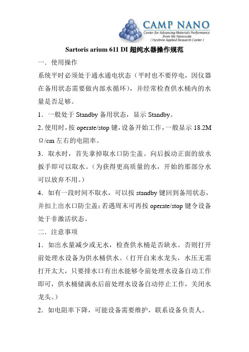
一.使用操作
系统平时必须处于通水通电状态(平时也不要停电,因仪器在备用状态需要做内部水循环),并经常检查供水桶内的水量是否足够。
1.一般处于Standby备用状态,显示Standby。
2.使用时,按operate/stop键,设备开始工作,一般显示18.2M Ω/cm左右的电阻率。
3.取水时,首先拿掉取水口防尘盖。
向后扳动正面的放水扳手即可以取水。
(为获得更高质量的水,开始的那部分水可以放弃不用。
)
4.如有一段时间不取水,可以按standby键回到备用状态,并扣上出水口防尘盖;若遇周末可再按operate/stop键令设备处于非激活状态。
二.注意事项
1.如出水量减少或无水,检查供水桶是否缺水。
否则打开前处理水设备为供水桶供水。
(打开自来水龙头,水压无需打开太大,只要排水口有出水能够令前处理水设备自动工作即可,供水桶储满水后前处理水设备自动停止工作,关闭水龙头。
)
2.如电阻率下降,可能设备需要维护,联系设备负责人。
超纯水机标准操作规程

超纯水机标准操作规程陕西百盛园生物科技信息有限公司文件标题超纯水机标准管理制度页数 4 文件编码BSY-SB-BG-020 分发部门颁发部门起草人日期审核人日期批准人日期执行日期变更记载修订号批准日期执行日期更变原因及目的1.目的建立一个超纯水机的使用维护保养程序。
2.范围适用于超纯水机。
3.责任人操作人员、设备管理员及生产负责人。
4.内容4.1 适应范围:采用半透体螺旋式膜分离去除水中的可溶性固体、有机物、胶体物质及细菌,使用于满足于工艺用水要求的场所。
4.2 技术要求:水温4°C—45°CpH范围4—9硬度 17mg/L(以CaCO3计)浊度 SDI<5总溶解性固体含量 TDS<1000mg/L且原水必须符合以下要求:铁:<0.1mg/L有机物:<1mg/L4.3 防护措施4.3.1 搬运时,必须切断电源,开启移动滑轮锁。
4.3.2 搬运时必须缓慢移动,严禁倾斜倒置。
4.3.3 如有必要,须在四周粘贴泡沫板,以防划伤。
4.3.4 新安置地点必须坚实。
4.4 操作规程4.4.1 首先打开原水供水水源阀门,若有加压泵,则启动加压泵。
4.4.2设备若是第一次开机运行,则应打开保安过滤器前的排污口,肉眼观察原水干净后,关闭排污口,使原水进入保安过滤器。
4.4.3打开浓水调节阀,将泵后节流阀调整到适中状态,装有清洗口和清洗阀的设备,应先检查各阀是否按规定处于开或闭状态。
4.4.4 待精密过滤器滤后压力表上升0.05MPa,启动主机电源开关。
4.4.5设备会按照逆渗透系统主机动作原理开始工作。
4.4.6 主机运转后,逐渐开启泵后节流阀,调整浓水调节阀,使纯水和浓水比例达到额定指标,而后再调整泵后节水阀,使纯水产水量达到额定指标,浓水调节阀和泵后节流阀配合使用调整,满足以下条件:4.4.6.1 系统压力不应超过额定值,低压不应超过 1.55MPa,超低压不应超过1.05MPa。
超纯水机操作规程

超纯水机操作规程一、引言超纯水机是一种用于制备高纯水的设备,广泛应用于实验室、医疗、制药、电子等领域。
为了确保超纯水的质量和操作的安全性,制定本操作规程,以指导操作人员正确使用超纯水机。
二、超纯水机的组成和工作原理1. 超纯水机的组成超纯水机主要由预处理系统、反渗透系统、离子交换系统、超滤系统、电除菌系统等组成。
2. 超纯水机的工作原理超纯水机通过预处理系统去除水中的杂质和溶解氧,然后通过反渗透系统去除大部分离子和有机物质,接着通过离子交换系统进一步去除离子,再经过超滤系统去除细菌和颗粒物,最后通过电除菌系统杀灭残留的微生物,得到高纯度的超纯水。
三、超纯水机的操作步骤1. 准备工作- 确保超纯水机的电源已连接并正常供电。
- 检查超纯水机的进水管道是否连接稳固,水源是否正常。
- 检查超纯水机的排水管道是否通畅。
2. 启动超纯水机- 打开超纯水机的电源开关,待设备启动完成后,进入待机状态。
- 按照设备说明书的要求,选择合适的操作模式。
3. 操作预处理系统- 打开预处理系统的进水阀门,确保水源畅通。
- 检查预处理系统的滤芯是否需要更换,如需要更换,按照操作手册的指导进行更换。
- 检查预处理系统的压力表,确保压力正常。
4. 操作反渗透系统- 打开反渗透系统的进水阀门,确保水源畅通。
- 检查反渗透系统的压力表,确保压力正常。
- 检查反渗透系统的膜元件是否需要清洗或更换,如需要清洗或更换,按照操作手册的指导进行操作。
5. 操作离子交换系统- 打开离子交换系统的进水阀门,确保水源畅通。
- 检查离子交换系统的树脂是否需要再生或更换,如需要再生或更换,按照操作手册的指导进行操作。
6. 操作超滤系统- 打开超滤系统的进水阀门,确保水源畅通。
- 检查超滤系统的滤芯是否需要更换,如需要更换,按照操作手册的指导进行更换。
7. 操作电除菌系统- 打开电除菌系统的电源开关,确保设备正常运行。
- 检查电除菌系统的紫外灯是否需要更换,如需要更换,按照操作手册的指导进行更换。
实验室超纯水机使用方法

设备操作流程
选择产水模式
根据需要选择超纯 水或去离子水模式。
取水
当水箱中的水达到 设定液位后,打开 取水阀开始取水。
打开电源开关
按下电源按钮,启 动超纯水机。
开始制水
设备开始制水,等 待水箱中的水达到 设定液位。
关闭电源
制水完成后,关闭 电源开关。
关机及日常维护
清洗设备表面
更换滤芯
定期使用湿布擦拭设备表面,保持清 洁。
根据设备使用情况定期更换滤芯,保 证水质。
检查水管连接
定期检查水管连接是否紧固,如有松 动及时处理。
03
注意事项
安全须知
确保电源安全
在连接或拆卸超纯水机时,应确保电源已关闭, 以防止触电。
避免使用刺激性化学品
在清洗或维护超纯水机时,应避免使用刺激性 化学品,以免对皮肤或眼睛造成伤害。
遵循操作说明
如何选择合适的超纯水机
需求分析
根据实验室用水需求,如用水量、水质要求等,选择适合的超纯 水机型号。
技术参数
比较不同超纯水机的技术参数,如产水流量、水质纯度、能耗等, 以选择性能更优的产品。
品牌信誉
选择知名品牌,确保产品质量和售后服务有保障。
品牌与售后服务的重要性
品牌信誉
选择知名品牌能够保证产品质量和性 能的可靠性,降低使用风险。
结果
使用超纯水机后,实验结果更加准确可靠,且大幅降低了实验成本。
成功案例二:制药企业的应用
1 2
背景
某制药企业需要高纯度水用于药品制备和生产。
解决方案
采用实验室超纯水机,结合反渗透技术,去除水 中的杂质和微生物。
3
结果
超纯水机出水质量稳定,满足制药企业生产需求, 提高了药品质量和安全性。
Arium611uv安装步骤

______________________________________________________________________________________ 德国赛多利斯公司北京代表处1Arium 611 VF 安装步骤一.打开包装1.检查包装有无破损。
小心打开包装盒,把设备取出水平放置到台面上。
去掉塑料袋,检查设备有无运输毁坏2.取出附件,附件放置在主机里面和包装盒上面部分3.滤柱单独放在一个包装箱里,打开这个包装箱取出滤柱二.安装1.把主机放置在一个合适的台面上。
2.显示/取水模块安装A .用四个螺丝和垫圈,把显示/取水模块安装在门上B .把显示/取水模块的电缆和位于主机里面上半部分的系统电缆连接上C .显示/取水模块的两条水管通过门里侧的四个孔穿绕出来D .主机里面右侧有两个做好颜色标记的水管连接头,把显示/取水模块的两条也做有颜色标记的水管按照颜色相对应扣插到主机里面的水管连接头E .把蓝色印有UV/UF 字样的塑料条安装在门的另一个门洞3.排水管连接A .主机右侧下半部分的出口连接头应该用排水管连接好。
把排水管插入出口连接头,确认管道扣紧B .排水管的另一头自然排放5.滤柱安装A .打开主机的前门B .先把帖有蓝色标签的滤柱放到主机内的左侧位置,标签冲外,面向自己,滤柱应该嵌入位于机器下部的托架C . 主机里的蓝色铝板拉至滤柱的顶部位置,安全防护滑扣面向自己,用全力把两个水管连接头摁进滤柱的对应的孔里,摁到位后,滤柱上的两个安全螺丝突出到铝板的上面D .把铝板上的两个安全防护滑扣往前推至滤柱上的安全螺丝,锁紧滤柱和铝板接头E .按照上述方法,再把帖有红色标签的滤柱安装到主机内的右侧位置6.终端过滤器安装A .确认主机取水阀门关闭B .拧下旧终端过滤器C .在新终端过滤器的螺纹上缠两至三圈密封带D .把新终端过滤器拧紧到主机取水阀上E .放掉约6升水7.电源:电源输入和主机开关位于主机左侧下半部分位置,用电源线连接到电源插座______________________________________________________________________________________德国赛多利斯公司北京代表处28.进水管连接:把进水管有快接头的一端插进位于主机左侧的进水口,进水管的另一端连接到水源三.操作1.Arium611 纯水机有6个用于系统控制和操作的按键,这6个功能键描述如下:STANDBY — 系统的内部循环流动每小时运行15分钟OPERATE/STOP — 按此功能键,系统开始运行或者停止。
超纯水机操作规程
超纯水机操作规程引言概述:超纯水机是一种用于制备高纯度水的设备,广泛应用于实验室、制药、电子等领域。
为了确保超纯水的质量和设备的正常运行,正确的操作规程是至关重要的。
本文将详细介绍超纯水机的操作规程,包括设备准备、操作步骤、常见问题及解决方法等。
正文内容:1. 设备准备1.1 检查设备及附件:确保超纯水机及其附件完好无损,并检查电源、水源等是否正常。
1.2 清洁设备:使用纯净水或去离子水清洗超纯水机的各个部件,确保设备表面干净,并清理水箱等容器。
2. 操作步骤2.1 开机操作2.1.1 打开电源开关:将超纯水机的电源开关打开,确保设备正常供电。
2.1.2 打开水源:打开水源开关,使水源进入超纯水机。
2.1.3 启动设备:按照设备说明书的要求,启动超纯水机,等待设备进入正常工作状态。
2.2 制备超纯水2.2.1 净水操作:按照设备说明书的要求,选择净水模式,使水经过预处理步骤,去除大部分杂质。
2.2.2 超纯水操作:选择超纯水模式,使水经过反渗透和电离子交换等步骤,去除更多的离子和有机物质,制备出高纯度的超纯水。
2.2.3 监测水质:使用水质检测仪器检测超纯水的电导率、溶解氧等指标,确保水质符合要求。
3. 常见问题及解决方法3.1 水质不合格3.1.1 检查水源:检查水源是否符合要求,如水质不好,可更换水源。
3.1.2 检查设备:检查超纯水机的滤芯、反渗透膜等部件是否需要更换或清洗。
3.1.3 联系维修人员:如问题仍未解决,及时联系设备维修人员进行维护。
3.2 设备故障3.2.1 检查电源:检查电源是否正常,如有问题,及时修复或更换。
3.2.2 检查水泵:检查水泵是否正常运转,如有异常,联系维修人员进行检修。
3.2.3 联系售后服务:如设备故障无法解决,及时联系售后服务进行维修。
3.3 设备维护3.3.1 定期清洗:定期清洗超纯水机的各个部件,如滤芯、反渗透膜等,以保证设备的正常运行。
3.3.2 定期更换:根据设备说明书的要求,定期更换滤芯、反渗透膜等易损件,以保证超纯水的质量。
超纯水发生器的操作规程
超纯水发生器操作规程版本状态:A/0 编号:简洁规范实用下载即用
编制:审核: 批准:执行日期:年月日1
超纯水发生器的操作规程
1.目的
规范超纯水发生器Arium611的使用和维护。
2.范围
本规程适用于超纯水发生器Arium611的使用和维护。
3.系统组成
本系统由超纯水发生器,两条水管,电源线,一个消毒注射器,超滤器,用户手册等组成。
4.程序
4.1 确定水源开关为打开状态
4.1.1 把3/8 外径进水管有快接头的一端插进位于主机左侧的进水口。
4.1.2 把进水管的另一端安装好连接适配头,连接到水源。
4.1.3 打开水源开关。
4.2 打开主机电源
4.2.1 系统自检。
完成后,用户按MENU键进入系统管理菜单。
4.2.2 按OPERATE/STOP键启动机器,进入运行模式。
打开取水阀取水。
4.2.3 在运行模式期间,水一直在内部循环流动,系统显示电导率,日期,时间。
4.3 待机模式 STANDBY
4.3.1 系统处于待机模式,每小时运行15分钟的内部循环流动。
4.3.2 当每小时用水量小于2升时,建议使用待机模式。
超纯水机操作规程
超纯水机操作规程
标题:超纯水机操作规程
引言概述:超纯水机是实验室中常用的设备,用于制备高纯度水,保证实验的准确性和可靠性。
正确操作超纯水机对于保证实验结果的准确性至关重要。
本文将详细介绍超纯水机的操作规程。
一、准备工作
1.1 确保超纯水机已经连接好电源,并且水箱中已经装满了去离子水。
1.2 检查超纯水机的滤芯是否需要更换,如有需要,及时更换。
1.3 确保周围环境整洁,无杂物干扰。
二、开机操作
2.1 打开超纯水机的电源开关,待机器启动完成自检后,进入工作状态。
2.2 按照超纯水机的操作说明,设置所需的纯度水质。
2.3 等待超纯水机工作完成,确认出水口的水质符合要求后,可以进行下一步操作。
三、操作注意事项
3.1 在操作过程中,不要随意更改超纯水机的设置,以免影响水质。
3.2 长时间不使用超纯水机时,应该关闭电源开关,以免浪费电能。
3.3 定期清洁超纯水机的出水口和水箱,保持设备的干净卫生。
四、停机操作
4.1 在使用完毕后,应该关闭超纯水机的电源开关。
4.2 清洁超纯水机的出水口,并将水箱中的水排空。
4.3 定期检查超纯水机的滤芯和其他部件,确保设备的正常运行。
五、故障处理
5.1 如果超纯水机出现故障,应该立即停止使用,并联系专业维修人员进行维修。
5.2 不要私自拆卸超纯水机的部件,以免造成更大的损坏。
5.3 在维修期间,应该暂停使用超纯水机,以免影响实验的进行。
结尾:正确操作超纯水机是保证实验准确性的重要保障,希望大家能够严格按照操作规程进行操作,确保实验结果的准确性和可靠性。
超纯水机操作规程
超纯水机操作规程
《超纯水机操作规程》
一、超纯水机的启动与停止
1. 检查超纯水机的电源接线,确认接地良好后才能启动超纯水机。
2. 打开超纯水机的控制面板,按照操作手册上的步骤进行开机操作。
3. 在停止使用超纯水机时,先按照操作手册上的步骤进行关机操作,然后断开电源。
二、操作超纯水机的注意事项
1. 使用高纯水作为原水源,确保原水的质量对超纯水机的影响最小。
2. 定期对超纯水机进行清洁和维护,确保运行稳定。
3. 根据操作手册上的指示,定期更换超纯水机的滤芯和相关配件。
三、超纯水机的故障处理
1. 在超纯水机出现故障时,立即停止使用,并关闭电源。
2. 根据操作手册上的故障排除流程,逐步进行检查和修复。
四、超纯水机的安全事项
1. 在操作超纯水机时,要做好相关防护措施,避免发生意外伤害。
2. 不得在超纯水机周围摆放易燃物品,以防止发生火灾。
五、使用超纯水的注意事项
1. 超纯水仅限于实验室使用,不得用于饮用或其他非实验室用途。
2. 在使用超纯水时,要注意防止其受到污染,确保其纯度不受影响。
通过严格遵守以上超纯水机操作规程,可以确保超纯水机的正常运行,并延长其使用寿命,同时也保障了超纯水的纯度和安全性。
- 1、下载文档前请自行甄别文档内容的完整性,平台不提供额外的编辑、内容补充、找答案等附加服务。
- 2、"仅部分预览"的文档,不可在线预览部分如存在完整性等问题,可反馈申请退款(可完整预览的文档不适用该条件!)。
- 3、如文档侵犯您的权益,请联系客服反馈,我们会尽快为您处理(人工客服工作时间:9:00-18:30)。
______________________________________________________________________________________
记的水管按照颜色相对应扣插到主机里面的水管连接头
7.把蓝色印有 UV/UF 字样的塑料条安装在门的另一个门洞
排水管连接
1.主机右侧下半部分的出口连接头应该用排水管连接好。排水管插入出口连接头约 20mm,确认管道扣紧
2.排水管的另一头自然排放
超滤器初始安装
1.打开主机的两个前门 2.找到各标有 inlet(绿色),reject(红色),product(蓝色)的水管连接头 3.超滤器底部(feed),顶部(reject),左上部(product)各有连接头 4.取出超滤器,主机里面的水管连接头和超滤柱上的水管连接头一一对应连接,用手拧紧 5.把超滤器扣放在相应的卡槽里
地址 :北京市朝阳区望ddress : Room 212, Donghuqu, Wangjiang Industrial Zone, Chaoyang District, Beijing 100102, China
目录
安全信息 系统规格 打开包装
附件清单
______________________________________________________________________________________
3
德国赛多利斯公司北京代表处
Sartorius AG Beijing Representative Office
地址 :北京市朝阳区望京工业园区东湖渠 212 室
于机器下部的托架 3.把主机里面的蓝色铝板拉至滤柱的顶部位置,安全防护滑扣面向自己,用全力把两个水
管连接头摁进滤柱的对应的孔里,摁到位后,滤柱上的两个安全螺丝突出到铝板的上面 4.把铝板上的两个安全防护滑扣往前推至滤柱上的安全螺丝,锁紧滤柱和铝板接头 5.按照上述方法,把帖有红色标签的滤柱安装到主机内的右侧位置 6.冲洗新滤柱
地址 :北京市朝阳区望京工业园区东湖渠 212 室
邮编:100102
Address : Room 212, Donghuqu, Wangjiang Industrial Zone, Chaoyang District, Beijing 100102, China
注意:Arium 纯水机提供两种进水管连接适配头,一种是 1/2”英制螺纹,一种是 1/4”公制 螺纹。连接适配头随设备一起提供
警告:确信墙体和安装硬件与系统重量相匹配,如果安装不适当会导致人身伤害和设备毁 坏
在墙上安装 Arium 纯水机需要 25 英寸乘 25 英寸的空间。一个墙上安装用支架包含在附件里 面,用它定位在墙上预先钻孔,然后用螺丝把该支架钉在墙上。用双手把主机抱起来,使主 机后部的两个大孔对准支架上的栓子,稍稍往下放置把主机挂在支架上
注意:上述水质的自来水做水源仅仅用于每天用水量少于 5 升的情况下 进水压力:最大 7bar 出水水质:18.2MΩ-cm,TOC<1ppb,内酶素<0.001Eu/ml,微生物<1CFU/100ml
出水量:最大 1.5l/min
电源:交流 100-240V/50-60HZ
操作环境:温度 5-28℃,相对湿度 80%,无凝结
邮编:100102
Address : Room 212, Donghuqu, Wangjiang Industrial Zone, Chaoyang District, Beijing 100102, China
安全信息
警告:指有潜在的人身伤害危险 小心:指可能造成设备损害 注意:特别提示信息
系统规格
注意:滤柱单独放在一个包装箱里,打开这个包装箱取出滤柱
安装
系统台面安装
把主机放置在一个合适的台面上。保证有足够的空间。确认进水,排水和电源
系统墙上安装
注意:设备不包含墙上安装用的螺丝
______________________________________________________________________________________
安装
系统台面安装 系统墙上安装 显示/取水模块安装 排水管连接 超滤器初始安装 UV 灯 滤柱初始安装 终端过滤器安装 电源连接/开关 进水管连接
启动/操作
键盘 初始启动 运行模式 待机模式 停机模式
系统设置
时间/日期 设定点 测量单位 语言
通用功能
打印机 设置传感器常数
维护保养
更换超滤器 超滤器冲洗 UV 灯使用寿命计时 UV 灯更换
邮编:100102
Address : Room 212, Donghuqu, Wangjiang Industrial Zone, Chaoyang District, Beijing 100102, China
注意:UV 和 VF 系统配有 UV 灯
注意: Arium 611 纯水机第一次使用前,参考本手册 UV 灯使用寿命计时部分,重设 UV 灯 计时器
2.取出附件,放置在主机里面和包装盒上面部分的附件与主机一起运输。参考以下附件清 单
附件清单
● 显示/取水模块 ● 装配显示/取水模块的螺丝垫圈 ● 两个进水管连接适配头(1/2”British&1/4”NPT) ● 两条水管,进水管和排水管 ● 蓝色印有 Arium 字样的扣在取水处的塑料扣板 ● 蓝色印有 UV/UF 字样的塑料软条 ● 墙上安装用支架 ● 电源线 ● 超滤器 ● 管道出口 ● 一个消毒注射器 ● 带有 O 型圈的滤柱连接适配头 ● 消毒用接口的终端盖帽 ● UV 灯 ● 用户手册
UV 灯
______________________________________________________________________________________
6
德国赛多利斯公司北京代表处
Sartorius AG Beijing Representative Office
地址 :北京市朝阳区望京工业园区东湖渠 212 室
地址 :北京市朝阳区望京工业园区东湖渠 212 室
邮编:100102
Address : Room 212, Donghuqu, Wangjiang Industrial Zone, Chaoyang District, Beijing 100102, China
打开包装
1.检查包装有无破损。小心打开包装盒,把设备取出水平放置到台面上。去掉塑料袋,检 查设备有无运输毁坏
储存环境:温度 5-45℃,相对湿度 80%,无凝结
______________________________________________________________________________________
4
德国赛多利斯公司北京代表处
Sartorius AG Beijing Representative Office
Arium 611 VF 用户手册
______________________________________________________________________________________
1
德国赛多利斯公司北京代表处
Sartorius AG Beijing Representative Office
OPERATE/STOP — 按此功能键,系统开始运行或者停止。在运行模式期间,水一直在内部 循环流动;停止模式时,水泵停,水停止内部循环流动
MENU — 进入系统管理菜单
UP/DOWN — 光标上/下移动键。允许用户移动光标在显示屏幕中的位置,或者修改数据和 选择相应的设定
ENTER — 回车确认键
5
德国赛多利斯公司北京代表处
Sartorius AG Beijing Representative Office
地址 :北京市朝阳区望京工业园区东湖渠 212 室
邮编:100102
Address : Room 212, Donghuqu, Wangjiang Industrial Zone, Chaoyang District, Beijing 100102, China
电源输入和主机开关位于主机左侧下半部分位置,用适当的电源线连接到电源插座
进水管连接
______________________________________________________________________________________
7
德国赛多利斯公司北京代表处
Sartorius AG Beijing Representative Office
1.确定用哪一种连接适配头来固定你的进水管 2.把 3/8 外径进水管有快接头的一端插进位于主机左侧的进水口 3.把进水管的另一端安装好连接适配头,连接到水源 4.打开水源开关
启动/操作
键盘
Arium611 纯水机有 6 个用于系统控制和操作的按键,这 6 个功能键描述如下
STANDBY — 系统的内部循环流动每小时运行 15 分钟
显示/取水模块安装
1.显示/取水模块设计有三种安装方式
A.系统台面搁置时,该模块安装在主机右侧门的顶部 B.系统墙上安装时,该模块安装在主机右侧门的底部 C.该模块可以安装在其它位置,遥控操作(需要订购额外的部件)
2.确定好显示/取水模块安装在门的哪个位置 3.用四个螺丝和垫圈,把显示/取水模块安装在门上 4.把显示/取水模块的电缆和位于主机里面上半部分的系统电缆连接上 5.显示/取水模块的两条水管通过门里侧的四个孔穿绕出来 6.主机里面右侧有两个做好颜色标记的水管连接头,把显示/取水模块的两条也做有颜色标
邮编:100102
Address : Room 212, Donghuqu, Wangjiang Industrial Zone, Chaoyang District, Beijing 100102, China