探头说明书(中英文版)
山电-雷达探头系列配件说明书

1.2Important safety instructions1.Read these instructions.2.Keep these instructions.3.Heed all warnings.4.Follow all instructions5.Clean only with a dry cloth.6.Install in accordance with the manufacturer's instructions.7.Do not install unit near any heat sources such as radiators, heat registers, stoves, or other apparatus (including amplifiers) that produce heat.8.Protect the power cord from being walked on or pinched particularly at plugs, convenience receptacles, and the point where they exit from the apparatus.9.Only use attachments/accessories specified by themanufacturer.10.Unplug this apparatus during lightning storms or whenunused for long periods of time.11.Refer all servicing to service personnel. Servicing isrequired when the apparatus has been damaged in any way, such as power-supply cord or plug is damaged, liquid has been spilled or objects have fallen into the apparatus, the apparatus has been exposed to rain or moisture, does not operate normally, or has been dropped.1.3FCC & ICES complianceFCC & ICES InformationThis equipment has been tested and found to comply with the limits for a Class B digital device, pursuant to part 15 of the FCC Rules . These limits are designed to provide reasonable protection against harmful interference in a residential environment . This equipment generates, uses, and can radiate radio frequency energy and, if not installed and used in accordance with the instructions, may cause harmful interference to radio communications. However, there is no guarantee that interference will not occur in a particular installation. If this equipment does cause harmful interference to radio or television reception, which can be determined by turning the equipment off and on, the user is encouraged to try to correct the interference by one or more of the following measures:–reorient or relocate the receiving antenna;–increase the separation between the equipment and receiver;–connect the equipment into an outlet on a circuit different from that to which the receiver is connected;–consult the dealer or an experienced radio/TV technician for help.Intentional or unintentional modifications, not expressly approved by the party responsible for compliance, shall not be made. Any such modifications could void the user's authority to operate the equipment. If necessary, the user should consult the dealer or an experienced radio/television technician for corrective action.VDx-244 - Quick Install AM18-Q06421/2WDR Analog Camera Menus Setup menu | en 1 1Setup menuPress straight down on the button of the control pad to access the SETUPmenu.––Move the button to the right or left to change values.–Navigation items at the bottom of the screen –To move to the continuation of a menu, select NEXT .–To return to the previous menu, select BACK or RETURN .–To save changes, select SAVE ALL .–To close the SETUP menu, select EXIT .1.1Main menuLENS WHITE BAL WDR DNR DAY/NIGHTIMAGE ADJUSTGENERALWDR Analog Camera Menus Setup menu | en 2 1.1.1Lens menu–DSS (Digital Slow Shutter) increases the amount of light captured by the factor selected. Use only in scenes with little movement.LENSDCBRIGHTNESS 0~255AGC0~20FLICKERLESS ON, OFFDSSOFF, X2, X4, X6, X32, X64, 128X, X256, X512, SHUTTER1/60, 1/120, 1/250, 1/500, 1/1000, 1/2000, 1/4000,1/10000 (NTSC)1/50, 1/100, 1/250, 1/500,1/1000, 1/2000, 1/4000, 1/10000 (PAL)RETURNESCBRIGHTNESS 0~255AGC0~20FLICKERLESS ON, OFFDSSOFF, X2, X4, X6, X32, X64, 128X, X256, X512,RETURNWDR Analog Camera Menus Setup menu | en 3 1.1.2White balance menu–ATW (Auto Tracking White balance: 2,500K to 8,500K) and PUSH (Full pull-in: 1,800K to 10,500K) continuously analyze color temperature. –Use ANTI CR (Anti Color Rolling) when certain types of fluorescent light cause the picture to periodically change color.–Use PUSH LOCK with a reference white object filling the screen.WHTE BALATW ENVIRONMENT INDOOR, OUTDOOR RETURNPUSH USER1, USER2R-GAIN 0~255B-GAIN 0~255RETURNANTI CR ENVIRONMENT INDOOR, OUTDOOR MANUALB-GAIN UP B-GAIN DOWN PRESET RETURNPUSH LOCKWDR Analog Camera Menus Setup menu | en 41.1.3Wide dynamic range menu–WDR (Wide Dynamic Range) is a dual shutter exposure correction function for high contrast scenes to obtain images with fewer blown-out highlights and hidden shadows.–Use BLC (Back Light Compensation) to see a dark object in front of a bright background.–Use HLC (High Light Compensation) to darken highlights and avoid image wash-out (for example, car headlights).WDRWDRMODE WDR, DWDR BRIGHTNESS 0~255CONTRAST LOW, MID-LOW, MID, MID-HIGH, HIGHRETURNBLC AREA AUTO, MANUAL RETURN HLCCLIP LEVEL 0~255SCALE 0~15RETURNWDR Analog Camera Menus Setup menu | en 5 1.1.4Digital noise reduction menu–DNR (Digital Noise Reduction): In low ambient lighting conditions use 2DNR to reduce noise in still images; use 3DNR to reduce noise in scenes with movement.1.1.5Day/night menuDNR2DNR LEVEL LOW, MID, HIGHRETURN 3DNR LEVEL AUTO, LOW, MID, HIGH RETURNOFFDAY/NIGHTAUTODELAY CNT 0~15 SEC D/N LEVEL LOW, MID, HIGHRETURNCOLOR B/WBURST ON, OFFRETURNWDR Analog Camera Menus Setup menu | en 6 1.1.6Image adjust menu–DIS (Digital Image Stabilizer) electronically suppresses camera shake.IMAGE ADJUSTIMAGESHARPNESS 0~15GAMMA 0.38, 0.42, 0.45, 0.50, 0.55, 0.63, 0.71, 0.83HR MODE OFF, X1, X2, X3, X4, X5, X6, X7CONTRAST 0~63RETURND-EFFECTDIS ON, OFFD-ZOOM OFF, X2, X3, X4, X6, X8, X16MIRROR V-FFLIP, H-FLIP, HV-FLIP FREEZEON/OFF NEGA/POSI NEGA/POSIRETURN COLOR-GAINR-GAIN 0~63B-GAIN 0~63RETURNWDR Analog Camera Menus Setup menu | en 7 Image adjust menu - continuedArea selection for motion or privacy masks Select area 1, 2, 3 or 4.–Top : extend or reduce upper limit of detection area.–Bottom : extend or reduce bottom limit of detection area.–Left : extend or reduce left limit of detection area.–Right : extend or reduce right limit of detection area.MOTIONAREA 1/4, 2/4, 3/4, 4/4DISPLAY ON, OFF DETECT AREA SENSITIVY 0~15TOP 0~15BOTTOM 1~16LEFT 0~23RIGHT 1~24RETURNPRIVACYAREA 1/15~15/15DISPLAY ON, OFFPOSITION COLORGREEN, BLUE, YELLOW, CYAN, MAGENTA, WHITE,BLACK, REDTRANSP 0.00, 0.50, 0.75, 1.00MOSAIC ON, OFFRETURNRETURNWDR Analog Camera Menus Setup menu | en 8When the camera title is ON, a virtual keyboard appears on the screen. Use the control pad to move to the character you want and select it. Repeat this to enter the camera ID you desire. You can enter up to 52 characters.。
本特利振动探头中文说明书
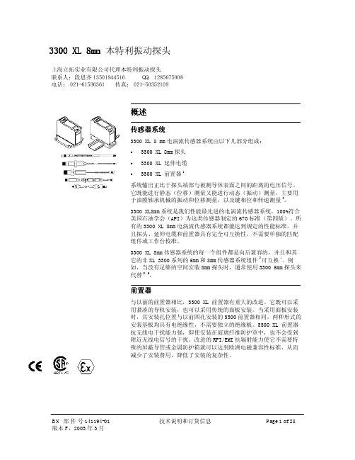
3300 XL 8mm 本特利振动探头概述传感器系统3300 XL 8 mm 电涡流传感器系统由以下几部分组成:• 3300 XL 8mm 探头 • 3300 XL 延伸电缆 •3300 XL 前置器1系统输出正比于探头端部与被测导体表面之间的距离的电压信号。
它既能进行静态(位移)测量又能进行动态(振动)测量,主要用于油膜轴承机械的振动和位移测量,以及键相位和转速测量2。
3300 XL8mm 系统是我们性能最先进的电涡流传感器系统,100%符合美国石油学会(API )为这类传感器制定的670标准(第四版)。
所有的3300 XL 8mm 电涡流传感器系统都能达到规定的性能标准,并且探头、延伸电缆和前置器具有完全可互换性,不需要单独的匹配组件或工作台校准。
3300 XL 8mm 传感器系统的每一个组件都是向后兼容的,并且和其它的非XL 3300系列的5mm 和8mm 传感器系统组件3可互换4。
例如,当没有足够的空间安装8mm 探头时,通常使用3300 5mm 探头来代替5,6。
前置器与以前的前置器相比,3300 XL 前置器有重大的改进。
它既可以采用紧凑的导轨安装,也可以采用传统的面板安装。
当采用面板安装时,其安装孔位置与以前四孔安装的3300前置器相同。
两种形式的安装基板均具有电绝缘性,不需要独立的绝缘板。
3300 XL 前置器抗无线电干扰能力强,即使安装在玻璃纤维防护罩中,也不会受到附近无线电信号的干扰。
改进的RFI/EMI 抗辐射能力使它不需要特殊的屏蔽导管或金属防护箱就可以达到欧洲电磁兼容性标准,从而减少了安装费用,降低了安装的复杂性。
上海立拓实业有限公司代理本特利振动探头联系人:段思齐13501944516 QQ:1285675908电话:021-61536361 传真:021-503521093300 XL的SpringLoc 端子带不需要特殊的安装工具即可紧固。
由于不需要螺丝紧固,不会发生松动,所以连线更坚固。
探头说明书(中英文版)

探头说明书(中英文版)Doppler 微波自动门感应探头——适用于各种自动门的传感器用户指南V1.0实现技术:微波及微处理器检测原理:Doppler 微波雷达原理发射频率:FCC X-band (10.525GHz )发射密度:<5mW/cm 2 安装高度:最大高度4m 检测区域(典型值):宽*长=3.5m*3m 检测模式:运动模式灵敏度调整:电位器调整温度范围:-25℃ ~ +65℃ 抗干扰性能:EMC 符合89/336EEC 标准电源电压(直流):12~24V DC 输出:标准继电器输出最大接点电压AC220V 或DC 35V 最大接点电流 1A 输出保持时间 1S 重量:70g 电缆长度:2m传感器结构说明:调整检测区域:用手指请按天线边缘沿着定轴回旋调整注意:传感器天线部分为静电敏感部位,调节过程一定要注意静电防护!灵敏度调节:用微型螺丝刀(梅花头)调节电位器,左旋为增大检测距离及灵敏度,右旋则减少。
安装注意事项:1、不要安装在淋雨或者漏水的地方2、不能安装在金属材料的后面,微波会被金属材料屏蔽3、检测区域内不能放置有持续移动或者振动的物体4、传感器应当固定好,防止振动5、根据自动门使用要求调节感应区域、感应距离及灵敏度传感器安装准备:安装前需要再安装门头上开孔穿线用一字螺丝刀从开启孔处将底座和外壳分开安装螺丝直径为4mm 传感器接线:传感器所配套电缆为4芯高可靠护套电缆红色黑色线为电源线(具有防反接功能),工作电压为12~24VDC 直流供电两根白色线为信号线(标准继电器输出)(1)(2)(3)(4)1、传感器接线端子2、电位器(调节灵敏度)3、传感器天线4、工作指示灯Technology: Microwave and microprocessorDetection Principle: Doppler microwave radar principleTransmitting frequency: the FCC X-band (10.525GHz) Emission density: <5mW/cm2 Installation height: maximum height of 4m Detection region (typical): W * L = 3.5m * 3m Detection modes: sport mode Sensitivity Adjustment: adjust the potentiometer Temperature range: -25 ℃ ~ +65 ° CAnti-interference performance and standards: EMC meets89/336EEC Supply voltage (DC): 12 ~ 24V DC Output: standard relay outputMaximum junction voltage: AC220V or DC 35V Maximum contact current: 1A Output hold time: 1S Weight: 70g Cable length: 2mAdjustment of the test area:According to the antenna edge with your fingers along the fixed axis maneuver to adjustNote: part of the sensor antenna for static-sensitive parts of the adjustment process must pay attention to electrostatic protection!Sensitivity adjustment:Using a micro-screw (Plum head) driver to adjust the potentiometer to increase the detection range and sensitivity, Turn Left increasing and turn Right decreased. Installation Notes:1, do not install in the place of rain or water leakage;2, can not be installed in the back of the metal material, micr owave will be shielded by metal materials;3, the detection area can not be placed in a continuously moving or vi brating object;4, the sensor should be fixed, to prevent vibration 5,Want to regulate the induction region, accordi ng to the use of automatic doors, the sensing range and sensitivity The sensor is installed to prepare: You'll need to install doorway openings threadingUsing a flathead screwdriver separate from the open hole at the base and shell Mounting screws of 4mm in diameter Sensor Wiring:Sensors be supporting cable for 4-core high reliability sheathed cableRed black wire power cord (with anti-reverse function), the working voltage of 12 ~ 24VDC power supply Two white lines for the signal line (standard relay outputs)(1)(2)(3)(4)1, the sensor terminal 2, potentiometers (adjust able sensitivity)3, the sensor antenna 4, the working indicator。
沃森E10探头指南说明书

Probe GuideVoluson E10Extraordinary visionExtraordinary vision starts with advanced probe technology. Based on feedback from physicians and sonographers, the Voluson probes have evolved to help meet your needs and include innovations that put advanced technology for women’s healthcare applications at your fingertips.The Voluson E10 supports a wide range of probes that help provide quality imaging – especially in complex first trimester, fetal heart and gynecological exams.The world’s first commercially available curved electronic matrix 4D probe provides superb resolution in all imaging planes and enables ultra-fast volume rates for real-time display of motion, allowing superb visibility of anatomical structures and functionality. You can rely on Voluson E10 probes to help deliver exceptional image quality.4C-D H4001BCC1-5-D H40452LERAB2-5-D H48651MNRAB6-D H48681MGRM6C H48671ZGeM6C H48681MJC4-8-D H48681AS11L-D H40432LN9L-D H40442LMML6-15-D H40452LGIC 5-9-D H40442LKRIC5-9-D H48651MS*Not available in all countriesRIC6-12-D H48651NARSP6-16-D H48651MR*S4-10-D H45302LA3Sp-D H48681AZ© 2014 General Electric Company – All rights reserved.General Electric Company reserves the right to make changes in specifications and features shown herein, or discontinue the product described at any time without notice or obligation. Contact your GE Representative for the most current information.GE, the GE monogram and Voluson are trademarks of General Electric Company or one of its subsidiaries.GE Healthcare, a division of General Electric Company.JB22307XXaEuropeGE Healthcare Beethovenstr. 239 D - 42655 Solingen T 49 212 2802 0 F 49 212 2802 28APACGE Healthcare Asia Pacific 4-7-127, Asahigaoka, Hino-shi, Tokyo 191-8503 JapanT +81 42 585 5111。
探头中文说明简单式
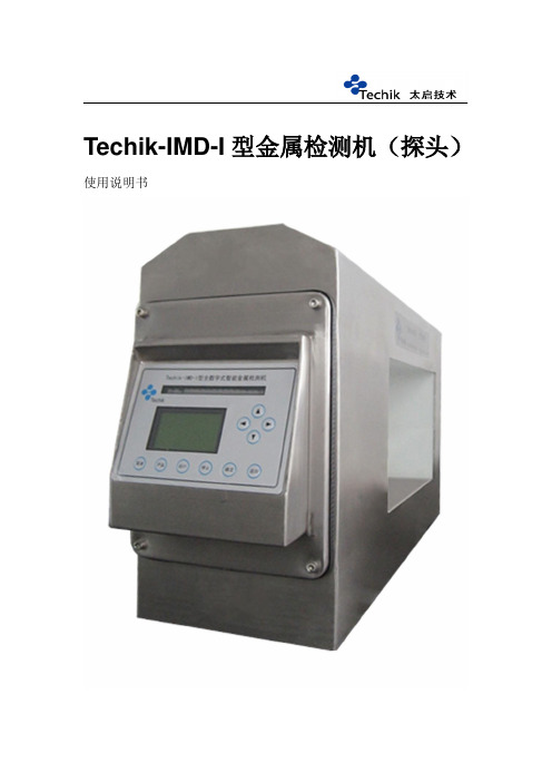
Techik-IMD-I型金属检测机(探头)使用说明书在使用本产品前,请务必阅读本说明书。
请将本说明书与产品一起保管。
写在前面的话为了防止因设备使用而发生的人身伤害或造成的财产损失,在设备上粘贴的标志有必要特别加以阐述。
请充分理解这些标志的含义,服从有关规定的注意事项。
1.触电在电机上面有左图所示的标志,为带高压电。
在此部位的操作要十分注意。
2.警告当在有左图所示标志的场所工作时,请务必参照本说明书使用。
若未阅读使用说明书而进行操作时,则可能造成人身伤害事故。
此外,也有可能成为设备性能降低的原因。
3.接地向本设备供电时,请保证电源插座能与三芯电源线相匹配,以保证设备能接地。
若设备未接地而工作,则有可能发生负伤甚至触电事故。
4.禁止拍在探头上方的这个标志显示禁止用大力拍,这个部位直接影响检测的精度,产生误警,从而带来不必要的损失。
前言本说明书对Techik-IMD-I型金属检测机的安装、操作和保养进行了说明。
撰写本说明书是以本设备的操作者和维护人员为阅读对象。
关于金属检测机的金属检测能力说明:金属检测机不能保证能检测出所有的金属。
它能检测到的金属取决于被检查品的种类(尺寸、形状、导电性等)和金属的种类(材质、形状等)以及安装环境。
实际的金属检测能力以设备交货前发行的规格书或交货安装时所确认的值为标准。
第一章概述1.1、金属检测机简介金属检测机是采用电磁耦合平衡接收的原理来检查在传送带流水线上传送的被检查品。
当检测出设定值以上的金属信号时,蜂鸣器报警,电机停止运转(设定)。
1.2、标准品的组成金属检测机1台使用说明书1本测试块(以φ1.5mm为例)是选购件。
Feφ1.5mm ·测试块Test Sample上海太启信息技术有限公司SUS304φ1.5mm ·测试块Test Sample上海太启信息技术有限公司1.3、各部分的名称和功能控制面板处理来自探测头的检测信号,金属混入时显示,并对该设备进行整体控制。
中文说明书--Hydrolab DS5X,DS5和MS5水质多功能探头

6.8.1标准参比电极………………………………………………………………………….......………………………………….…45
6.8.2 pH全能传感器………………………………………………………………………….......………………………..………..…46
5.2.4最低流量要求…………………………………………………………………….......………………….………………………35
5.2.5不能潜水时的配置……………………………………………………………….......………………....………………………35
第6章维护………………………………………………………………………….......…………………………...........………………37
4.1.6其他参数设置……………………………………………………………………………………………………………………22
4.2校正….………………..……………………………………………………........………………………………………………………22
4.2.1使用测量器校正传感器…………………………………………………...............……………………………………………22
4.3.1使用测量器收集数据…………………………………………………………………………………………..................……27
4.3.2使用PC和Hydras 3 LT收集数据………………………………………………………………………………………………27
4.3.3使用DS5/DS5X/MS5进行无人监测……………………………………………………………………………………..……27
超声波超音波探头PHH-1X用户说明书
OMEGA is LI registered trademark of OMEGA ENGINEERING, INC.
QCopyright 1992 OMEGA ENGINEERING. INC. All rights reserved including illustrations. Nothing in this manual
PHH-1X LITMUSTIK” pH Tester M1008/0592
GENERAL DESCRIPTION
The OMEGA PHH-1X Litmustik@ is an economical handheld unit small enough to fit in a pocket. This newly designed pH tester features large display numerics for easy reading, and single point calibration. Designed for fast evaluations in the field, this high performance tester measures the entire pH range from 0 to 14 pH units and offers better accuracy than test paper ’.
Soak the sensing tip in either buffer 4, buffer 7, KCL solution or tap water for at least
30 minutes. Make sure that the sensing tip is immersed up to at least one inch from
工业视觉探头产品说明书
Industrial VideoscopeFeatures and SpecificationsAdvanced Test Equipment Rentals 800-404-ATEC (2832)®E s t a b l i s h e d 1981Advanced Test Equipment Corp. 800-404-ATEC (2832)Construction:Dimensions:Weight:Pelican™ brand case made of Polypropylene Copolymer material.24.6 in x 11.9 in x 19.3 in (624 mm x 303 mm x 491 mm)22.0 lb (10 kg)Carrying CaseInternal Battery:AC Power:Voltage: 14.8 V nominal, 11.5 V to 16.8 V Operating Time: 150 minutes (min)Input Voltage: 100 V to 240 V Supply Frequency: 50/60 Hz (with supplied AC adapter)Power SupplyModel Number:Dimensions:Weight:Construction:IV8000-29.8 in x 6.3 in x 11.2 in (250 mm x 160 mm x 285 mm)10.8 lb (4.9 kg), including battery.Cast magnesium alloy chassis.Video Output:Audio Input:Auxiliary Connector:USB:S-Video, Composite BNC (NTSC/PAL-region specific).External microphone, 3.5 mm mono jack.Two-way communication connector for future interface development.One USB connector for direct flash drive recording and PC communication.Hardware ConnectorsLCD Panel:LCD Resolution:LCD Controls:LCD Mounts:6.5-inch daylight-view LCD, low reflection type VGA High Resolution 640 x 480Dedicated LCD power, brightness control, 180º image rotate, TITLE and NOTE buttons located on LCD panel.A standard 1/4”–20 mount on base.LCD SpecificationsBase UnitEach interchangeable scope unit consists of the handheld control unit and insertion tube. Scope unit attaches to the base unit with two secure latches. Available in NTSC or PAL format models (region specific).Dimensions:Weight:Quick access buttons:12.2 in x 3.7 in x 7.6 in (311 mm x 93 mm x 192 mm)1.7 lb (750 g)The following features have dedicated quick access buttons, leversor joysticks on the hand control unit: Live mode, WiDER™ Gain Control, Brightness, Zoom, Freeze Image, Record Still/Video, Articulation Control, Articulation Lock, Menu Access, Saved Recording Index Access, Quick Last Image Recall.Scope UnitArticulation Mechanics:Temperature Sensor:TrueFeel ™ scope tip articulation with electronic power-assisted, manual articulation.2-stage indicator for high temperature warning.Insertion TubeHandheld Control UnitScalar Measurement:Stereo MeasurementDistan c e:Point-to-Line:Depth:Area/Lines:Profile:Multi:Offset:Distance between two points based on a known measurement in the same image plane.Distance between two points.Perpendicular distance between a point and a user-defined line.Orthogoral depth/height distance between a point and a user-defined plane.Multiple point circumference and area measurement.Plot of cross section between two points.Multiple measurements (distance, point-to-line, area and line) between two points.Point-to-Line measurement with a parallel line passing on a measurement point.The operating environment performance is confirmed by the followingMIL-STD-810F and MIL-STD-461E under battery operation. Refer to instructions manual for more details.Vibration:Shock:Water Resistance:Humidity:Salt Fog:Sand and Dust:Electromagnetic Interference (EMI):Explosive Atmosphere:MIL-STD-810F, Method 514.5, Procedure I (General vibration test).MIL-STD-810F, Method 516.5, Procedure IV (Transit drop test).MIL-STD-810F, Method 506.4, Procedure I (Rain and Blowing rain test).MIL-STD-810F, Method -STD-810F, Method 509.4MIL-STD-810F, Method 510.4, Procedure I (Blowing dust test).MIL-STD-461E, RS-103, (Radiated susceptibility testfor non-metallic below deck shipboard conditions).MIL-STD-810F, Method 511.4, Procedure I (Operation in an explosive atmosphere test). MIL-STD ComplianceImage Controls:Adjustable Gain Control:Noise Reduction: Color Enhancement:Exposure Control:Display Text Options:3x digital zoom9 step digital brightness control5 step contrast adjustment for frozen and retrieved images.4 step adjustable gain control with exclusive WiDER™ brightness level balancing technology.Decreases static interference in images.Monochrome mode or Color Emphasis of red, blue or all primary colors.Adjustable CCD exposure time.PAL: 20 ms to 500 ms NTSC: 17 ms to 500 ms* fixed minimum exposure time for stereo measure- ment mode.Selectable date, time and 30-character title display.Software ControlsIPLEX FX features seven different measurement modes. Scalar measurement is available with all standard viewing tip adapters. Stereo measurements require a stereo tip adapter.Measurement FunctionsModel No.Exterior WeightTube Flexibility Scope Diameter Scope Length Articulation Angle UP/DOWN/RIGHT/LEFT Fixed hard tube from the distal end of the insertion tube to the control unit.Fixed hard tube from the distal end of the insertion tube to the control unit.Tungsten with special processing Tungsten with special processingSmooth resinø4.0 mm (0.157 in)ø6.0 mm (0.236 in)ø6.0 mm (0.236 in)ø6.2 mm (0.244 in)3.7 lb (1.7 kg)4.2 lb (1.9 kg)3.7 lb (1.7 kg)4.2 lb (1.9 kg)4.4 lb (2.0 kg)4.9 lb (2.2 kg)TTF tube with flexibility gradually increasing toward the distal end.IV8420IV8435IV8620IV8635IV8635X1IV8650IV8675IV8675X2IV86120IV861802.0 m (6.6 ft)3.5 m (11.5 ft)2.0 m (6.6 ft)3.5 m (11.5 ft)5.0 m (16.4 ft)7.5 m (24.6 ft)12.0 m (39.4 ft)18.0 m (59.1 ft)3.5 m (11.5 ft)with working channelScope Unit150º130º110º120º90º5.7 lb (2.6 kg)70º 6.8 lb (3.1 kg)50º130ºResolution:Format and Size of aSingle Image (for NTSC)*:Overlay:Audio Overlay:PAL: 768 x 576; NTSC: 640 x 480Standard Viewing Tip Adapters:JPEG - super high quality (SHQ); approx 350 KBhigh quality (HIGH); approx 300 KB standard quality (STD); approx 200 KBStereo Tip Adapters:JPEG (HIGH); approx 300 KBUncompressed TIFF; approx 640 KBSelectable 30 character title with date, time and system settings. Additional data can be input to an image using the ImageNotepad tool which provides the capability to insert up to 10 additionaldescriptions to an image, displayed by categories and contents. Up to 12 characters can be input for the category field and 28 characters for content field.WAV format, 60 sec max.; 16 KB/secStill Image RecordingResolution:Format:Recording Time:Audio:PAL: 384 x 288/768 x 576NTSC: 320 x 240/640 x 480AVI format, Motion JPEG compression, Windows. Media Player compatible.Approx 30 minute per 1 GB.Optional selectable before recording.Video RecordingRecording Media:Internal Memory:Image Management Functions:Compact Flash Card (1 GB standard, compatible with recommended Compact Flash cards up to 4 GB .USB Flash Drive recommended.1 GB standard.Search by date, Live/Saved image comparison.Recording Management Functions*The still image recording capacity of the PAL format is approximately 140% of the NTSC format.*3. Indicates the length of the rigid portion at the scope’s distal end when mounted.*2. The adapter can be inserted into a ø4.0 mm, ø6.0 mm or ø6.2 mm hole when it is mounted on the scope. *1. Indicates the optimal focal distance of the tip adapter.Product abbreviation Character color Optical systemField of view Direction of view Depth of field *1Fno.Distal endOuter diameter *2Distal end *3AT40D/IV8640D V86Black 40ºForward 200 to ∞ mm2.4ø6.0 mm 19.8 mmAT80D/NF-IV8680DN V86Red 80ºForward 8 to ∞ mm9.5ø6.0 mm 19.8 mmAT80D/FF-IV8680DF V86Green 80ºForward 35 to ∞ mm3.1ø6.0 mm 19.8 mmAT120D/NF-IV86120DN V86Red 120ºForward 4 to 190 mm9.2ø6.0 mm 19.8 mmAT120D/FF-IV86120DF V86Green 120ºForward 25 to ∞ mm3.3ø6.0 mm 19.8 mmAT80S-IV8680S V86Black 80ºSide 18 to ∞ mm4.0ø6.0 mm 25.2 mmAT120S/NF-IV86120SN V86Red 120ºSide 1 to 25 mm9.6ø6.0 mm 25.2 mmAT120S/FF-IV86120SF V86Green 120ºSide 5 to ∞ mm5.9ø6.0 mm 25.2 mm6 mm Viewing Tip AdaptersTip Adapter Optical SpecificationsOperating Temperature:Operating Atmospheric Pressure:Relative Humidity:Liquid Resistance:Waterproofing:Operating Temperature:Operating Atmospheric Pressure:Relative Humidity:Liquid Resistance:Waterproofing:In air: –13º to 212ºF (–25º to 100ºC)Note: Angulation to a large angle may become difficult at low temperatures.In water: 50º to 86ºF (10º to 30ºC)In air: 1013 hPa (1 atm)In water: 1013 to 1772 hPa (1 to 1.75 atm)*15 to 90%Operable when exposed to machine oil, light oil or 5% saline solution.Operable under water with viewing tip adapter attached*. Not operable underwater with stereo measurement tip adapters.In air: –5.8º to 120ºF (–21º to 49ºC)In air: 1013 hPa (1 atm)15 to 90%Operable when exposed to machine oil, light oil or 5% saline solution.Operable in blowing rain conditions (Battery compartment must be closed). Not operable underwater.Operating EnvironmentInsertion TubeAll Other System Parts (Base Unit, Hand Control Unit)4.0 mm and 6.2 mm Viewing Tip AdaptersRed Green Red Green AT120D/NF-IV84AT120D/FF-IV84AT120S/NF-IV84AT120S/FF-IV84Product abbreviation 120DN V84120DF V84120SN V84120SF V84Character colorOptical systemField of view120º120º120º120ºDirection of view Forward Forward Side Side Depth of field *1 4 to 190 mm1 to 20 mmFno.9.2 3.39.6 6.0Distal endOuter diameter *2ø4.0 mm ø4.0 mm ø4.0 mm ø4.0 mm Distal end *319.7 mm19.6 mm22.2 mm22.2 mm25 to ∞ mm6 to ∞ mm* Excluding IV8635X1Locking Mechanism:Illumination:Tip Adapter Identification:Double Threaded Attachment, with O-ring seal.Multiple high intensity LEDs with 2-stage illumination.Automatic SmartTip™ Recognition Technology.Tip Adapter General SpecificationsLow Voltage Directive and EMC Directive:FCC Information:WEEE Directive:RoHS Directive: This device complies with the requirements of Directive 73/23/EEC and 93/68/EEC concerning electrical equipment designed for use within certain voltage limits.This device complies with Part 15 of the FCC Rules. Operation is subject to the following twoconditions: (1) this device may not cause harmful interference received, including interference that may cause undesired operation. This class A digital apparatus complies with Canadian ICES-003. In accordance with European Directive 2002/96/EC on Waste Electrical and Electronic Equipment, this symbol indicates that the product must be disposed of as unsorted municipal waste, but should be collected separately. Refer to your local Olympus distributor for return and/or collection systems available in your country.RoHS compliance model.External Application StandardsRed Green Black Black AT120D/NF-IV86X1AT120D/FF-IV86X1AT80S-IV86X1AT120S-IV86X1120DN V86X1120DF V86X180S V86X1120S V86X1120º120º80º120ºForward Forward Side Side 4 to 190 mm18 to ∞ mm9.2 3.3 4.0 5.9ø6.2 mm ø6.2 mm ø6.2 mm ø6.2 mm 20.6 mm20.5 mm24.7 mm24.7 mm25 to ∞ mm6 to ∞ mmStereo Tip Adapters (4.0 mm, 6.0 mm and 6.2 mm)Blue Blue Blue Blue AT50D/50D-IV84AT50S/50S-IV84AT60D/60D-IV86AT60S/60S-IV86Product abbreviation 50/50D V8450/50S V8460/60D V8660/60S V86Character colorOptical systemField of view50º/50º50º/50º60º/60º60º/60ºDirection of view Forward/Forward Side/Side Forward/Forward Side/Side Depth of field *1Fno.7.57.57.57.5Distal endOuter diameter *2ø4.0 mm ø4.0 mm ø6.0 mm ø6.0 mm Distal end *325.0 mm28.8 mm25.9 mm32.2 mm4 to ∞ mm5 to ∞ mm5 to ∞ mm4 to ∞ mm5 to ∞ mmBlue Blue AT60D/60D-IV86X1AT60S/60S-IV86X160/60D V86X160/60S V86X160º/60º60º/60ºForward/Forward Side/Side 7.57.5ø6.2 mm ø6.2 mm 25.9 mm32.9 mm4 to ∞ mmIPLEX Viewer SoftwareUSB KeyboardAC AdapterTip Adapter Carrying CaseOptical Tip AdapterGuide TubeMAJ-1825-50/-75/-120/-180(for 5.0 m/7.5 m/12.0 m/18.0 m length insertion tube)4.0 mm (0.236 inch) and 6.0 mm (0.157 inch)Scope UnitMAJ-1737(for ø4.0 mm insertion tube, Outer diameter ø5.9 mm)Retrieval tools for Working Channel Scope MAJ-1354 (Alligator) MAJ-1357 (Magnet) MAJ-1356 (Grasper) MAJ-1355 (Basket) MAJ-1353 (Snare)MAJ-1245 (Hook Assembly)MAJ-1253(for ø6.0 mm/ø6.2 mm insertion tube, Outer diameter ø7.5 mm)6.2 mm (0.244 inch)Working Channel Scope UnitLCD Extension Cabble NP-L7SJL-2PLUS/OL-0 (115V)JL-2PLUS/OL-1 (220V)。
SUSS PH150探头头说明书
SUSS PH150 PROBEHEAD▲Robust, backlash-free, submicron probing▲Superior mechanicaland ergonomic design▲True, independent X, Y and Z linear travel▲Precision cross roller slides and bearings▲High-resolution positioningscrews▲Strong vacuum basewithout deviation at release ▲Single and double arms with goldcollet clamping▲Conductive, scratch andcorrosion-resistant nickel finishThe SUSS line of manual probeheadsoffers the advantages of proven highquality, superior mechanical andergonomic design, and completeproduct line compatibility.The SUSS PH150 has proved to bethe most accurate and robustpositioner on the market. By usingthe finest precision components andexpert assembly techniques, SUSSachieves true submicron positioningwith zero backlash.The PH150 incorporates an independ-ent and uninfluenced XYZ stagesystem which is free of mechanicalcross-talk deviation. Each stage ismade of hardened steel and precisioncross roller bearings assembled underexact torque measurements.In addition to superior mechanicaldesign, SUSS always adheres todetail regarding ergonomics andflexibility. Each axis has 10 mm oftravel with 50 or 100-tpi (threadsper inch), high-resolution screws.A C C E S S O R Y D E S C R I P T I O NMANUAL PROBEHEAD PH150KARL SUSS WORLDWIDE▲GERMANYKARL SÜSS KG · GmbH & Co.Schleissheimer Strasse 90D-85748 Garching bei München · Germany Tel (+49) [0]89/3 20 07-0, Fax -1 62KARL SUSS Dresden GmbH Süss-Strasse 1D-01561 Sacka bei Dresden · Germany Tel (+49) [0]3 52 40 -730, Fax -73700▲FRANCEKARL SUSS France SARL KARL SUSS Technique S.A.Avenue des Colombières F-74490 Saint Jeoire · FranceTel (+33)-[0]450358-392, Fax -801▲GREAT BRITAINKARL SUSS Great Britain Ltd.23 Ivanhoe RoadHogwood Industrial EstateFinchampstead · Wokingham · Berkshire GB-RG40 4QQ · EnglandTel (+44)-[0]1189-732144, Fax -734395▲JAPANKARL SUSS Japan K.K. · YokohamaTel (+81)-[0]45-931-5600, Fax -5601▲ASIAKARL SUSS Asia Co., Ltd. 212/2 Soi Ladprao 10Ladprao Road, Ladyao · Jatujak Bangkok 10900 · Thailand Tel (+66) - 2 938 44 -26, -27Fax (+66) - 2 512 5569▲NORTH AMERICAKARL SUSS America Inc. P.O. Box 157, Suss DriveWaterbury Center · VT 05677 · USA Tel (+1) 802-244-5181, Fax -5103▲INTERNET / WWW Representatives in over 30 countries.Please visit the web site for our address list.The Z-axis screw is ergonomically located at the rear of the probe head body so as not to transmit finger pressure to the probe needle on touch down. The user has the choice of a Z axis with left or right-handed threads.The PH150 vacuum base system has superior holding strength. The entire footprint is encompassed by a rectangular rubber lip. Actuation is controlled by a convenient, body-mounted, “easy touch” lever. This system gives the operator complete control of probehead positioning,without gross probe needle deviation in the Z direction!The PH150 is compatible throughout the SUSS product line. The PH150is finished in electroless nickel,which is both scratch and corrosion-resistant. Probe arms are available for all applications, whether standard or special.A D .P H 150.U S .0797 · E K S 991033 · K S D .K S M .I S M .S S G .2000 · P r i n t e d i n G e r m a n y o n c h l o r i n e -f r e e b l e a c h e d p a p e r · S u b j e c t t o c h a n g e w i t h o u t p r i o r n o t i c e。
点位探头探头装置(套装)说明书
Point Level Probe AssemblyBody (Fitting) StyleC 1-1/2”Tri-Clamp (1)B 2”Tri-ClampD 2-1/2”Tri-ClampE 3”Tri-ClampSensor Wiring0 Quick Disconnect Receptacle (QDR)1 QDR w/connector (field wireable)2 QDR w/25 ft Standard Molded Cordset3 QDR w/50 ft Standard Molded Cordset 5 QDR w/100 ft Standard Molded Cordset Number of Probes1 One (1) Probe2Two (2) Probes3Three (3) Probes4 Four (4) Probes5 One (1) Probe offsetProbe CoatingT TeflonProbe Length (2) (Probes 1-4)00 None03 3”Long06 6”Long12 12”Long18 18”Long24 24”Long30 30”Long36 36”Long42 42”Long48 48”Long54 54”Long60 60”Long66 66”Long72 72”Long L BProbe1Probe2Probe3Probe4Point Level Switch ModulesRelay Type1 SPDT(Select with A and K sensitivity) - Fixed Sensitivity3 SPDT(Select with Y and Z sensitivity) -Adjustable Sensitivity Sensitivity /ActionA800 ohm Direct (Pump down)K 800 ohm Reverse (Pump up)Y Adjustable Sensitivity Direct (Pump down)Z Adjustable Sensitivity Reverse (Pump up)Supply Voltage1 110 VACSocket Style1 Octal 8 pin (Relay type 1)2 Octal 11 pin (Relay type 3)L LFutureLL-_-_-_-_-XX-XXMatrix NumberOrder Matrix Codes Wiring for Multiple“Single Point”ServiceModule 1Module3Module 2ProbeLiquid Contact StainlessTerminal HHousing LugScrew -Through WirePath Of Completed Circuit (Example)Anderson Instrument Co., Inc.156Auriesville Rd. ~ Fultonville, NY12072Phone: 518-922-5315Fax: 518-922-8997Reach us on the World Wide WebThis product carries a one (1) year warranty againstmanufacturers defects.A complete warranty statementis available by contacting Anderson, or in downloadableformat from the World Wide Web.Installation and Startup GuideModel LB Conductivity Based PointProbeModel LL Switch ModuleRev. 3.2 Document 1112Be sure to keep moisture from entering the probe housingprior to completing field installation and startup. Uponinstallation, be sure no moisture path exists into housing.Properly seal all junction boxes, flexible conduit orcustomer supplied cable grips.Relay Type 3 DimensionsRelay Type 1 DimensionsControl Design (Relay Type 1 & Type 3)Solid state components enclosed in clear Lexan plug-in stylehousing. Housing carries NO NEMA rating.Contact Design (Relay Type 1 & Type 3)SPDT(1 for C): one normally open (N.O.) and one normallyclosed (N.C.) non-powered contactsContact Ratings (Relay Type 1 & Type 3)10A@ 240 VAC resistive, 1/3 HP@ 120,240 VACContact Life (Relay Type 1 & Type 3)Mechanical 5 million operations. Electrical 100,000 operationat rated minimum load.Supply Voltage (Relay Type 1 & Type 3)120 VAC (per model), plus 10%, minus 15%, 50/60HzSupply Current (Relay Type 1 & Type 3)120 VAC, Relay energized 4.4 VA.Secondary Circuit (Relay Type 1 & Type 3)12 VAC RMS voltage on probes, 1.5 milliamp current.Sensitivity (Relay Type 1)Operate from 0-1,000,000 ohm maximum specific resistanceSensitivity (Relay Type 3)Operate from 0-1,000,000 ohm maximum specific resistance.Field adjustable.Temperature (Relay Type 1 & Type 3)-40 to 150 deg F, ambientTerminals (Relay Type 1 & Type 3)All connections #6-32 screw type terminals with pressure clampsTime Delays (Relay Type 1 & Type 3)Standard, .5 seconds on rising levelListing (Relay Type 1 & Type 3)U.L. listed, industrial Motor Control (508)LL Switch Module SpecificationsREADTHISFIRSTNotes:1. 1-1/2”Tri-Clamp available with one (1) or two (2) probes only.2.All standard probe lengths listed are available at standard lead times (consultfactory). Probes may be specified to the nearest whole inch between 3”and 72”bysimply inserting the length in the part number.3. Offset probe is available for 1-1/2”and 2”tri-clamp only. Probe offset from fittingnterline: 1-1/2”= 0.34”, 2”= 0.58”NOTE-Alternate Wiring:It is also possibleto connect switch module Terminal G toEarth Ground,with no connection to thehousing lug screw.The active path will gofrom probe,through liquid medium,throughvessel,through earth ground back intoswitch module completing circuit.Material and Finish Fitting and Probe:316L grade stainless steelProbe diameter (including coating): .44”diameter Probe coating / insulation 0.03”min. thickness, FEPProbe/Fitting SealFood Grade, Elastomeric Compression Seals. 3-A and USP , Class IV compliant Stainless steel and coating:Ra better than 25 micro-inchesOperationalTemperature Range 30 to 200 deg F (-1 to 94 deg C)Vacuum or vented non-pressurized vessels Pressure Range:-30”Hg to 100 psigCompliance Ratings-Assembly meets 3-A criteriafor Sensors and Sensor Fittings and Connections (#74-01)- Optional quick disconnect meets NEMA 4X requirements (In connected and dis-connected positions)Probe SpecificationsBaby Foods 1k Molasses 10k Beer 2.2k Mustard 1k Bourbon 200k Oil Soluble 10k Buttermilk 1k Soap Foam 18k Cake Batter 5k Soups 1k Catsup 2.2k Starch Solutions 5k Cream1k Sugar Solutions 90k Cream (Foam) 4.7k Vinegar Aqueous 2.2k Coffee2.2k Carbonated Water 3k Corn Syrup45k Condensated Water 18k Corn Cream Style 2.2k Chlorinated Water 5k Jam / Jelly45k Distilled Water 450k Juices Fruit / Veg 1k De-ionized Water 2.0m Mayonnaise 5k Hard / Natural Water 5k Milk1k Wine 2.2kNote: Under normal conditions, select a module sensitivity just higher than appropriate for the product. For low sensitivity liquids (Milk / Cream),when foaming is normally present, use 800 ohm module sensitivity to ignore foam and 4.7K ohm to 5K ohm sensitivity to sense foam.Typical Product Sensitivity ValuesEach of the modules is supplied from the factory in a Direct or Inverse mode of operation. Referring to the product matrix descriptions, determine the mode of operation for your module.The following definitions explain the action that will occur with each of the specific modules.SWITCH MODULE ACTION IS FACTORY SET,AND MAY NOT BE CHANGED IN THE FIELDDirect Mode Operation (Pump Down) Single Level ServiceWhen the liquid rises to the probe tip, the module energizes, changing the state of the load contacts.At this time, the internal LED will be lit.The module remains energized until the liquid recedes below the probe tip.The module then de-energizes, turning off the internal LED, and returning the switch contacts to their original shelf state.Typical Operation: High level alarmInverse Mode Operation (Pump Up) Single Level ServiceThe module energizes with power, changing the state of the load contacts.At this time, the internal LED will be lit. When the liquid reaches the probe tip the module de-energizes, turning off the internal LED, and returning the switch contact to the original shelf state.The module remains de-energized until the liquid level recedes below the desired high switch point.The module then energizes, changing the state of the load contacts.Typical Operation: Low level alarmDirect Mode Operation (Pump Down) Differential ServiceWhen the liquid rises to the “High”setpoint (probe on terminal 3) the module energizes, changing the state of the load contacts.At this time, the internal LED will be lit.The module remains energized until the liquid recedes below the “Low”setpoint (probe on terminal 4).The module then de-energizes,turning off the internal LED, and returning the switch contacts to their original shelf state.Typical Operation:You have a vessel that you do not want to overfill, but also do not want to fall below a certain level. When the product reaches the level of the high probe, a pump is started to transfer product to another vessel. When the level recedes below the low probe, the pump stops.Inverse Mode Operation (Pump Up) Differential ServiceThe module energizes with power, changing the state of the load contacts.At this time, the internal LED will be lit. When the liquid rises to the “High”setpoint (probe on terminal 3) the module de-energizes, turning off the internal LED, and returning the switch contacts to their original shelf state.The module remains de-energized until the liquid level recedes below the “Low”setpoint (probe on terminal 4).The module then energizes, changing the state of the load contacts.Typical Operation:You have a vessel that you do not want to go empty. When you apply power to the module, the pump turns on and fills the vessel until you reach the level of the high probe.The pump then shuts off. If you fall below the level of the low probe, the pump will start again to keep the vessel filled.Top - Looking Inside2Black1RedTop - Looking Inside3Green1Red2BlackTop - Looking Inside3Green1Red2Black4BlueTop - Looking Inside3Green1Red2Black4Blue5WhiteDetailColor coding for Andersonsupplied CableIf using a Type 3 Variable Sensitivity module, changes to the sensitivity may be made in the field.The following diagram shows placement for individual resistors.The following chart illustrates the resistor values used to achievethe desired sensitivity.Two resistors will be required for the value selected.Sensitivity Required (Kohm)Resistor Value Required (Kohm)4.75.110.010.026.027.050.051.0100.0100.0470.0390.01,000.0680.0Placement of ShuntResistors11 Pin Octal Socket(125K) 127K(250K)475K (400K)700K (500K)If using a variable sensitivity resistor board, installation is shown in figure 14. If two fixed resistors are already in place on the terminal screws of the socket, remove prior to installation of the variable resistor board.Variable Resistor Board Part number: 56014R0070The sensitivity range of the Variable Sensitivity Board is from 5K ohm to 700K ohm.These settings are achieved via the dual “One Turn”potentiometers located on the board.As the sensitivity increases in a non-linear ohm/turn ratio, you may use the chart shown above to achieve the proper setting.BOTH potentiometers should be set to equal position for proper operation. Setting should be at approximately 5% greater than that necessary for the product in the vessel.You may refer to the chart shown in Figure 8 for sample sensitivity values.One ProbeTwo ProbesThree ProbesFour Probes2 = Lug screw to housing 1 = Probe3 = Lug screw to housing 1 = Shortest Probe 2 = Longest Probe3 = Lug screw to housing 1 = Shortest Probe2 = Next Longest Probe 4 = Longest Probe3 = Lug screw to housing 1 = Shortest Probe2 = Next Longest Probe 4 = Next Longest Probe 5 = Longest ProbeField Modifications to Probe LengthsProbe lengths are available in one-inch increments from 3”to 72”. If a probe length mustbe field modified, consult Technical Service for proper guidelines and procedures.Adjustable Sensitivity (Utilizing add on resistors)Adjustable Sensitivity (Utilizing add on board)Pin 1 - RedPin 1 - RedDetailColor coding for Andersonsupplied CableDetailColor coding for Andersonsupplied CableDetailColor coding for Andersonsupplied Cable。
- 1、下载文档前请自行甄别文档内容的完整性,平台不提供额外的编辑、内容补充、找答案等附加服务。
- 2、"仅部分预览"的文档,不可在线预览部分如存在完整性等问题,可反馈申请退款(可完整预览的文档不适用该条件!)。
- 3、如文档侵犯您的权益,请联系客服反馈,我们会尽快为您处理(人工客服工作时间:9:00-18:30)。
Doppler 微波自动门感应探头——适用于各种自动门的传感器 用户指南V1.0
实现技术:微波及微处理器
检测原理:Doppler 微波雷达原理
发射频率:FCC X-band (10.525GHz ) 发射密度:<5mW/cm 2 安装高度:最大高度4m 检测区域(典型值):宽*长=3.5m*3m 检测模式:运动模式 灵敏度调整:电位器调整 温度范围:-25℃ ~ +65℃ 抗干扰性能:EMC 符合89/336EEC 标准 电源电压(直流):12~24V DC 输出:标准继电器输出
最大接点电压AC220V 或DC 35V 最大接点电流 1A 输出保持时间 1S 重量:70g 电缆长度:2m
传感器结构说明:
调整检测区域:
用手指请按天线边缘沿着定轴回旋调整
注意:传感器天线部分为静电敏感部位,调节过程一定要注意静电防护! 灵敏度调节:
用微型螺丝刀(梅花头)调节电位器,左旋为增大检测距离及灵敏度,右旋则减少。
安装注意事项:
1、 不要安装在淋雨或者漏水的地方
2、 不能安装在金属材料的后面,微波会被金属材料屏蔽
3、 检测区域内不能放置有持续移动或者振动的物体
4、 传感器应当固定好,防止振动
5、 根据自动门使用要求调节感应区域、感应距离及灵敏度 传感器安装准备:
安装前需要再安装门头上开孔穿线
用一字螺丝刀从开启孔处将底座和外壳分开 安装螺丝直径为4mm 传感器接线:
传感器所配套电缆为4芯高可靠护套电缆 红色黑色线为电源线(具有防反接功能),工作电压为12~24VDC 直流供电 两根白色线为信号线(标准继电器输出)
(1) (2) (3)
(4)
1、 传感器接线端子
2、 电位器(调节灵敏度)
3、 传感器天线
4、 工作指示灯
Technology: Microwave and microprocessor
Detection Principle: Doppler microwave radar principle
Transmitting frequency: the FCC X-band (10.525GHz) Emission density: <5mW/cm2 Installation height: maximum height of 4m Detection region (typical): W * L = 3.5m * 3m Detection modes: sport mode Sensitivity Adjustment: adjust the potentiometer Temperature range: -25 ℃ ~ +65 ° C
Anti-interference performance and standards: EMC meets 89/336EEC Supply voltage (DC): 12 ~ 24V DC Output: standard relay output
Maximum junction voltage: AC220V or DC 35V Maximum contact current: 1A Output hold time: 1S Weight: 70g
Cable length: 2m
Adjustment of the test area:
According to the antenna edge with your fingers along the fixed axis maneuver to adjust
Note: part of the sensor antenna for static-sensitive parts of the adjustment process must pay attention to electrostatic protection!
Sensitivity adjustment:
Using a micro-screw (Plum head) driver to adjust the potentiometer to increase the detection range and sensitivity, Turn Left increasing and turn Right decreased. Installation Notes:
1, do not install in the place of rain or water leakage;2, can not be installed in the back of the metal material, micr owave will be shielded by metal materials;3, the detection area can not be placed in a continuously moving or vi brating object;4, the sensor should be fixed, to prevent vibration 5,Want to regulate the induction region, accordi ng to the use of automatic doors, the sensing range and sensitivity The sensor is installed to prepare:
You'll need to install doorway openings threading
Using a flathead screwdriver separate from the open hole at the base and shell Mounting screws of 4mm in diameter Sensor Wiring:
Sensors be supporting cable for 4-core high reliability sheathed cable
Red black wire power cord (with anti-reverse function), the working voltage of 12 ~ 24VDC power supply Two white lines for the signal line (standard relay outputs)
(1) (2) (3)
(4)
1, the sensor terminal 2, potentiometers (adjust able sensitivity)
3, the sensor antenna 4, the working indicator。