
PLANETGEARBRUSHLESSDCMOTOR无刷行星齿轮减速
行星齿轮减速器中英文翻译英文资料
附录附录1:英文原文Planetary GearsIntroductionThe Tamiya planetary gearbox is driven by a small DC motor that runs at about 10,500 rpm on 3.0V DC and draws about 1.0A. The maximum speed ratio is 1:400, giving an output speed of about 26 rpm. Four planetary stages are supplied with the gearbox, two 1:4 and two 1:5, and any combination can be selected. Not only is this a good drive for small mechanical applications, it provides an excellent review of epicycle gear trains. The gearbox is a very well-designed plastic kit that can be assembled in about an hour with very few tools. The source for the kit is given in the References.Let's begin by reviewing the fundamentals of gearing, and the trick of analyzing epicyclic gear trains.Epicyclic Gear TrainsA pair of spur gears is represented in the diagram by their pitch circles, which are tangent at the pitch point P. The meshing gear teeth extend beyond the pitch circle by the addendum, and the spaces between them have a depth beneath the pitch circle by the dedendum. If the radii of the pitch circles are a and b, the distance between the gear shafts is a + b. In the action of the gears, the pitch circles roll on one another without slipping. To ensure this, the gear teeth must have a proper shape so that when the driving gear moves uniformly, so does the driven gear. This means that the line of pressure, normal to the tooth profiles in contact, passes through the pitch point. Then, the transmission of power will be free of vibration and high speeds are possible. We won't talk further about gear teeth here, having stated this fundamental principle of gearing.If a gear of pitch radius a has N teeth, then the distance between corresponding points on successive teeth will be 2πa/N, a quantity called the circular pitch. If two gears are to mate, the circular pitches must be the same. The pitch is usually stated as the ration 2a/N, called the diametral pitch. If you count the number of teeth on a gear, then the pitch diameter is the number of teeth times the diametral pitch. If you know the pitch diameters of two gears, then you can specify the distance between the shafts.The velocity ratio r of a pair of gears is the ratio of the angular velocity of the driven gear to the angular velocity of the driving gear. By the condition of rolling of pitch circles, r = -a/b = -N1/N2, since pitch radii are proportional to the number of teeth. The angular velocity n of the gears may be given in radians/sec, revolutions per minute (rpm), or any similar units. If we take one direction of rotation as positive, then the other direction is negative. This is the reason for the (-) sign in the above expression. If one of the gears is internal (having teeth on its inner rim), then the velocity ratio is positive, since the gears will rotate in the same direction.The usual involute gears have a tooth shape that is tolerant of variations in the distance between the axes, so the gears will run smoothly if this distance is not quite correct. The velocity ratio of the gears does not depend on the exact spacing of the axes, but is fixed by the number of teeth, or what is the same thing, by the pitch diameters. Slightly increasing the distance above its theoretical value makes the gears run easier, since the clearances are larger. On the other hand, backlash is also increased, which may not be desired in some applications.An epicyclic gear train has gear shafts mounted on a moving arm or carrier that can rotate about the axis, as well as the gears themselves. The arm can be an input element, or an output element, and can be held fixed or allowed to rotate. The outer gear is the ring gear or annulus. A simple but very common epicyclic train is the sun-and-planet epicyclic train, shown in the figure at the left. Three planetary gears are used for mechanical reasons; they may be considered as one in describing the action of the gearing. The sun gear, the arm, or the ring gear may be input or output links.If the arm is fixed, so that it cannot rotate, we have a simple train of three gears. Then, n2/n1 = -N1/N2, n3/n2 = +N2/N3, and n3/n1 = -N1/N3. This is very simple, and should not be confusing. If the arm is allowed to move, figuring out the velocity ratios taxes the human intellect. Attempting this will show the truth of the statement; if you can manage it, you deserve praise and fame. It is by no means impossible, just invoved. However, there is a very easy way to get the desired result. First, just consider the gear train locked, so it moves as a rigid body, arm and all. All three gears and the arm then have a unity velocity ratio.The trick is that any motion of the gear train can carried out by first holding the arm fixed and rotating the gears relative to one another, and then locking the train and rotating it about the fixed axis. The net motion is the sum or difference of multiples of the two separate motions that satisfies the conditions of the problem (usually that one element is held fixed). To carry out this program, construct a table in which the angular velocities of the gears and arm are listed for each, for each of the two cases. The locked train gives 1, 1, 1, 1 for arm, gear 1, gear 2 and gear 3. Arm fixed gives 0, 1, -N1/N2, -N1/N3. Suppose we want the velocity ration between the arm and gear 1, when gear 3 is fixed. Multiply the first row by a constant so that when it is added to the second row, the velocity of gear 3 will be zero. This constant is N1/N3. Now, doing one displacement and then the other corresponds to adding the two rows. We find N1/N3, 1 + N1/N3, N1/N3 -N1/N2.The first number is the arm velocity, the second the velocity of gear 1, so the velocity ratio between them is N1/(N1 + N3), after multiplying through by N3. This is the velocity ratio we need for the Tamiya gearbox, where the ring gear does not rotate, the sun gear is the input, and the arm is the output. The procedure is general, however, and will work for any epicyclic train.One of the Tamiya planetary gear assemblies has N1 = N2 = 16, N3 = 48, while the other has N1 = 12,N2 = 18, N3 = 48. Because the planetary gears must fit between the sun and ring gears, the condition N3 = N1 + 2N2 must be satisfied. It is indeed satisfied for the numbers of teeth given. The velocity ratio of the first set will be 16/(48 + 16) = 1/4. The velocity ratio of the second set will be 12/(48 + 12) = 1/5. Both ratios are as advertised. Note that the sun gear and arm will rotate in the same direction.The best general method for solving epicyclic gear trains is the tabular method, since it does not contain hidden assumptions like formulas, nor require the work of the vector method. The first step is to isolate the epicyclic train, separating the gear trains for inputs and outputs from it. Find the input speeds or turns, using the input gear trains. There are, in general, two inputs, one of which may be zero in simple problems. Now prepare two rows of the table of turns or angular velocities. The first row corresponds to rotating around the epicyclic axis once, and consists of all 1's. Write down the second row assuming that the arm velocity is zero, using the known gear ratios. The row that you want is a linear combination of these two rows, with unknown multipliers x and y. Summing the entries for the input gears gives two simultaneous linear equations for x and y in terms of the known input velocities. Now the sum of the two rows multiplied by their respective multipliers gives the speeds of all the gears of interest. Finally, find the output speed with the aid of the output gear train. Be careful to get the directions of rotation correct, with respect to a direction taken as positive.The Tamiya Gearbox KitThe parts are best cut from the sprues with a flush-cutter of the type used in electronics. The very small bits of plastic remaining can then be removed with a sharp X-acto knife. Carefully remove all excess plastic, as the instructions say.Read the instructions carefully and make sure that things are the right way up and in the correct relative positons. The gearbox units go together easily with light pressure. Note that the brown ones must go together in the correct relative orientation. The 4mm washers are the ones of which two are supplied, and there is also a full-size drawing of one in the instructions. The smaller washers will not fit over the shaft, anyway. The output shaft is metal. Use larger long-nose pliers to press the E-ring into position in its groove in front of the washer. There is a picture showing how to do this. There was an extra E-ring in my kit. The three prongs fit into the carriers for the planetary gears, and are driven by them.Now stack up the gearbox units as desired. I used all four, being sure to put a 1:5 unit on the end next to the motor. Therefore, I needed the long screws. Press the orange sun gear for the last 1:5 unit firmly on the motor shaft as far as it will go. If it is not well-seated, the motor clip will not close. It might be a good idea to put some lubricant on this gear from the tube included with the kit. If you use a different lubricant, test it first on a piece of plastic from the kit to make sure that it is compatible. A dry graphite lubricant would also work quite well. This should spread lubricant on all parts of the last unit, which is the one subject to the highest speeds. Put the motor in place, gently but firmly, wiggling it so that the sun gear meshes. If the sun gear is not meshed, the motor clip will not close. Now put the motor terminals in a vertical column, and press on the motor clamp.The reverse of the instructions show how to attach the drive arm and gives some hints on use of the gearbox. I got an extra spring pin, and two extra 3 mm washers. If you have some small washers, they can be used on the machine screws holding the gearbox together. Enough torque is produced at the output to damage things (up to 6 kg-cm), so make sure the output arm can rotate freely. I used a standard laboratory DC supply with variable voltage and current limiting, but dry cells could be used as well. The current drain of 1 A is high even for D cells, so a power supply is indicated for serious use. The instructions say not to exceed 4.5V, which is good advice. With 400:1 reduction, the motor should run freely whatever the output load.My gearbox ran well the first time it was tested. I timed the output revolutions with a stopwatch, and found 47s for 20 revolutions, or 25.5 rpm. This corresponds to 10,200 rpm at the motor, which is close tospecifications. It would be easy to connect another gearbox in series with this one (parts are included to make this possible), and get about 4 revolutions per hour. Still another gearbox would produce about one revolution in four days. This is an excellent kit, and I recommend it highly.Other Epicyclic TrainsA very famous epicyclic chain is the Watt sun-and-planet gear, patented in 1781 as an alternative to the crank for converting the reciprocating motion of a steam engine into rotary motion. It was invented by William Murdoch. The crank, at that time, had been patented and Watt did not want to pay royalties. An incidental advantage was a 1:2 increase in the rotative speed of the output. However, it was more expensive than a crank, and was seldom used after the crank patent expired. Watch the animation on Wikipedia.The input is the arm, which carries the planet gear wheel mating with the sun gear wheel of equal size. The planet wheel is prevented from rotating by being fastened to the connecting rod. It oscillates a little, but always returns to the same place on every revolution. Using the tabular method explained above, the first line is 1, 1, 1 where the first number refers to the arm, the second to the planet gear, and the third to the sun gear. The second line is 0, -1, 1, where we have rotated the planet one turn anticlockwise. Adding, we get 1, 0, 2, which means that one revolution of the arm (one double stroke of the engine) gives two revolutions of the sun gear.We can use the sun-and-planet gear to illustrate another method for analyzing epicyclical trains in which we use velocities. This method may be more satisfying than the tabular method and show more clearly how the train works. In the diagram at the right, A and O are the centres of the planet and sun gears, respectively. A rotates about O with angular velocity ω1, which we assume clockwise. At the position shown, this gives A a velocity 2ω1 upward, as shown. Now the planet gear does not rotate, so all points in it move with the same velocity as A. This includes the pitch point P, which is also a point in the sun gear, which rotates about the fixed axis O with angular velocity ω2. Therefore, ω2= 2ω1, the same result as with the tabular method.The diagram at the left shows how the velocity method is applied to the planetary gear set treated above. The sun and planet gears are assumed to be the same diameter (2 units). The ring gear is then of diameter 6. Let us assume the sun gear is fixed, so that the pitch point P is also fixed. The velocity of point A is twice the angular velocity of the arm. Since P is fixed, P' must move at twice the velocity of A, or four times the velocity of the arm. However, the velocity of P' is three times the angular velocity of the ring gearas well, so that 3ωr= 4ωa. If the arm is the input, the velocity ratio is then 3:4, while if the ring is the input, the velocity ratio is 4:3.A three-speed bicycle hub may contain two of these epicyclical trains, with the ring gears connected (actually, common to the two trains). The input from the rear sprocket is to the arm of one train, while the output to the hub is from the arm of the second train. It is possible to lock one or both of the sun gears to the axle, or else to lock the sun gear to the arm and free of the axle, so that the train gives a 1:1 ratio. The three gears are: high, 3:4, output train locked; middle, 1:1, both trains locked, and low, 4:3 input train locked. Of course, this is just one possibility, and many different variable hubs have been manufactured. The planetary variable hub was introduced by Sturmey-Archer in 1903. The popular AW hub had the ratios mentioned here.Chain hoists may use epicyclical trains. The ring gear is stationary, part of the main housing. The input is to the sun gear, the output from the planet carrier. The sun and planet gears have very different diameters, to obtain a large reduction ratio.The Model T Ford (1908-1927) used a reverted epicyclic transmission in which brake bands applied to the shafts carrying sun gears selected the gear ratio. The low gear ratio was 11:4 forward, while the reverse gear ratio was -4:1. The high gear was 1:1. Reverted means that the gears on the planet carrier shaft drove other gears on shafts concentric with the main shaft, where the brake bands were applied. The floor controls were three pedals: low-neutral-high, reverse, transmission brake. The hand brake applied stopped theleft-hand pedal at neutral. The spark advance and throttle were on the steering column.The automotive differential, illustrated at the right, is a bevel-gear epicyclic train. The pinion drives the ring gear (crown wheel) which rotates freely, carrying the idler gears. Only one idler is necessary, but more than one gives better symmetry. The ring gear corresponds to the planet carrier, and the idler gears to the planet gears, of the usual epicyclic chain. The idler gears drive the side gears on the half-axles, which correspond to the sun and ring gears, and are the output gears. When the two half-axles revolve at the same speed, the idlers do not revolve. When the half-axles move at different speeds, the idlers revolve. The differential applies equal torque to the side gears (they are driven at equal distances by the idlers) while allowing them to rotate at different speeds. If one wheel slips, it rotates at double speed while the other wheel does not rotate. The same (small) torque is, nevertheless, applied to both wheels.The tabular method is easily used to analyze the angular velocities. Rotating the chain as a whole gives 1, 0, 1, 1 for ring, idler, left and right side gears. Holding the ring fixed gives 0, 1, 1, -1. If the right side gear isheld fixed and the ring makes one rotation, we simply add to get 1, 1, 2, 0, which says that the left side gear makes two revolutions. The velocity method can also be used, of course. Considering the (equal) forces exerted on the side gears by the idler gears shows that the torques will be equal.ReferencesTamiya Planetary Gearbox Set, Item 72001-1400. Edmund Scientific, Catalog No. C029D, itemD30524-08 ($19.95).C. Carmichael, ed., Kent's Mechanical Engineer's Handbook, 12th ed. (New York: John Wiley and Sons, 1950). Design and Production Volume, p.14-49 to 14-43.V. L. Doughtie, Elements of Mechanism, 6th ed. (New York: John Wiley and Sons, 1947). pp. 299-311.Epicyclic gear. Wikipedia article on epicyclic trains.Sun and planet gear. Includes an animation.英文译文介绍Tamiya行星轮变速箱由一个约 10500 r/min,3.0V,1.0A的直流电机运行。
行星齿轮减速器参数
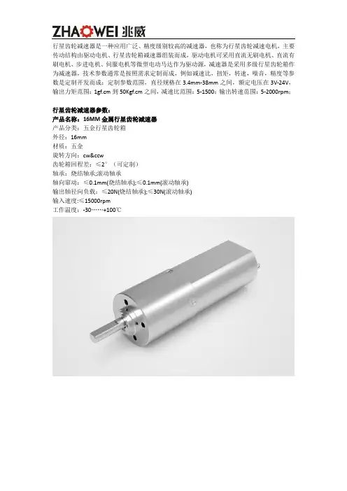
行星齿轮减速器是一种应用广泛、精度级别较高的减速器,也称为行星齿轮减速电机,主要传动结构由驱动电机、行星齿轮箱减速器组装而成,驱动电机可采用直流无刷电机、直流有刷电机、步进电机、伺服电机等微型电动马达作为驱动源,减速器是采用多级行星齿轮箱作为减速器,技术参数通常是按照需求定制而成,例如减速比,扭矩,转速,噪音,精度等参数是定制开发而成;定制参数范围,直径规格在3.4mm-38mm之间,额定电压在3V-24V,输出力矩范围:1gf.cm到50Kgf.cm之间,减速比范围:5-1500;输出转速范围:5-2000rpm;行星齿轮减速器参数:产品名称:16MM金属行星齿轮减速器产品分类:五金行星齿轮箱外径:16mm材质:五金旋转方向:cw&ccw齿轮箱回程差:≤2°(可定制)轴承:烧结轴承;滚动轴承轴向窜动:≤0.1mm(烧结轴承);≤0.1mm(滚动轴承)输出轴径向负载:≤20N(烧结轴承);≤30N(滚动轴承)输入速度:≤15000rpm工作温度:-30 (100)产品名称:20MM金属行星齿轮减速器产品分类:五金行星齿轮箱外径:20mm材质:金属旋转方向:cw&ccw齿轮箱回程差:≤3°(可定制)轴承:烧结轴承;滚动轴承轴向窜动:≤0.1mm(烧结轴承);≤0.1mm(滚动轴承)输出轴径向负载:≤30N(烧结轴承);≤50N(滚动轴承)输入速度:≤15000rpm工作温度:-20 (85)产品名称:24MM金属行星齿轮减速器产品分类:五金行星齿轮箱外径:24mm材质:五金旋转方向:cw&ccw齿轮箱回程差:≤2°(可定制)轴承:烧结轴承;滚动轴承轴向窜动:≤0.1mm;≤0.1mm输出轴径向负载:≤120N;≤170N输入速度:≤15000rpm工作温度:-30 (100)定制参数、规格范围:尺寸规格系列:3.4mm、4mm、6mm、8mm、10mm、12mm、16mm、18mm、20mm、22mm、24mm、28mm、32mm、38mm;电压范围:3V-24V功率范围:0.1W-40W输出力矩范围:1gf.cm到50Kgf.cm减速比范围:5-1500;输出转速范围:5-2000rpm;产品特点:行星齿轮减速器具备传动精度高、体积小、噪音低、耐用、耗能低、定制功率设计,安装方便,方便保养等特点;产品应用:行星齿轮减速器广泛应用在智能汽车驱动、智能通讯设备、智能医疗设备、智能物流设备、智能机器人设备、智能家居设备、消费电子产品设备、个人护理工具设备、自动工业化驱动设备中。
直流无刷马达简介BrushlessDCMotor

感應馬達
X X △ X △ △ ○ X ○ X X 較差
直流有刷馬達
△ △ X △ △ X X △ X △
轉子慣性低
高速度運轉性能 無轉子銅損 高效率 溫升低
無整流子,無碳刷摩 擦,無火花
低速扭力 免保養 過附載能力
五、應用實例(群真科技驅動器)
4 5
F/R FSP
藍 橙
6
R/S
白
7 8
COM 5V
黑 紅
JP4 接頭 [馬達/電源接線端, 12 Pin]
腳 位 1 2 3 4 5 名 稱 線色 BL5 BL9
馬達線圈U相 電源 DC24V+ (與JP1_+24V相通) 電源 GND NONE Hall Sensor電源, H- (與JP1_GND相通)
在低速運轉下,仍具備高輸出扭矩。 效率比傳統馬達好很多。 安靜、無噪音、免保養、壽命長。 使電動車輛擁有較高的續航力。 技術層次高,進入門檻高,附加價值 高。
三、直流無刷馬達與交流馬達之比較
傳統交流馬達
耗電量/效率 (相同作功)
直流無刷馬達
50W/90%
150WБайду номын сангаас35%
噪音
體積/重量 扭力 轉速 溫升
直流馬達的結構比較
(a)無刷
(b)有刷
二、直流無刷馬達的特點
具備體機小、重量輕、輸出功率大及高輸出扭 矩等特性。 採用電子換相結構,低電磁干擾,免碳刷保養, 速度可達10,000 rpm以上。 低轉子慣性,轉子體積比傳統感應馬達及有刷 馬達小很多,有較佳的控制性能。 馬達內轉子設計,線圈位於馬達定子中,定子 直接接觸散熱片,有極佳的散熱設計。
行星轮减速器原理

行星轮减速器原理行星轮减速器是一种常见的齿轮传动装置,其中包含了太阳轮、行星轮、内齿轮和输出轮等组成部分。
其主要原理是通过行星轮和太阳轮的齿轮传动,将输入轴上的高速运动转换为输出轴上的低速高扭矩运动。
行星轮减速器的主要工作原理如下:1. 输入轴通过太阳轮与行星轮相连,输入轴的高速旋转使太阳轮产生旋转。
2. 行星轮通过行星架与太阳轮相连,行星轮上有多个行星齿轮,它们能够同时绕行星架以及太阳轮中心旋转。
3. 内齿轮与行星轮的行星齿轮相连,内齿轮通过固定不动的连接轴与输出轮相连。
4. 当太阳轮旋转时,行星轮通过行星架在太阳轨道上旋转,使得行星齿轮与内齿轮齿咬。
这样,行星轮在太阳轮旋转的过程中,绕行星架并与内齿轮直接相连,使得内齿轮也随之旋转。
5. 最终输出轴通过内齿轮与内齿轮齿咬,从而转动。
行星轮减速器的优点是结构紧凑、承载能力强,且具有高精度、高刚度、高扭矩传递比的特点。
它可以提供大扭矩输出并实现多级传动,广泛应用于工业机械设备、自动化装置、航空航天等领域。
行星轮减速器的工作原理可以通过以下步骤详细描述:1. 输入轴上的高速运动驱动太阳轮旋转,太阳轮上的外齿与行星轮齿咬合。
2. 太阳轮驱动行星轮绕行星架旋转,此时行星轮上的行星齿轮也随之绕行星架旋转。
3. 行星轮上的行星齿轮通过齿咬与内齿轮齿咬合,内齿轮通过连接轴与输出轴相连。
4. 由于内齿轮的固定不动,行星轮的旋转会导致内齿轮也随之旋转,最终实现输出轴上的低速高扭矩输出。
行星轮减速器的减速比可以通过计算行星轮齿数、太阳轮齿数和内齿轮齿数的比例来确定。
减速比与齿数之间的关系公式为:减速比= (1 + 太阳轮齿数/ 行星轮齿数) ×(1 + 行星轮齿数/ 内齿轮齿数)当太阳轮、行星轮和内齿轮齿数满足特定比例时,可以实现不同的减速比。
通过改变行星轮的运动轨道和行星轮齿轮数量,还可以实现多级减速的效果。
需要注意的是,行星轮减速器在使用过程中也会产生一定的摩擦和热量,因此需要适时润滑,以确保其正常运转和延长使用寿命。
行星减速无刷直流电机

行星减速无刷直流电机行星减速无刷直流电机在现代工业中起着重要的作用。
它具有结构简单、体积小、噪音低、效率高等特点,被广泛应用于机器人、无人机、汽车、航空航天等领域。
行星减速无刷直流电机的工作原理是利用电磁学原理,通过电流产生的磁场与永磁体产生的磁场相互作用,从而产生转矩。
与传统的有刷直流电机相比,行星减速无刷直流电机无需接触式的刷子和换向器,因此具有更高的可靠性和寿命。
行星减速无刷直流电机的减速机构采用行星齿轮传动,其特点是结构紧凑、传动效率高、扭矩输出平稳。
行星减速器由外齿轮、内齿轮和行星齿轮组成,通过这种结构的设计,可以实现较大的减速比。
行星齿轮传动还具有承载能力强、运行平稳、噪音低等优点。
行星减速无刷直流电机广泛应用于机器人领域。
机器人是现代工业的重要组成部分,行星减速无刷直流电机作为机器人的关键驱动装置,可以实现机器人的精准运动控制。
在机器人的关节驱动中,行星减速无刷直流电机可以提供高扭矩输出,并且具有快速响应、高精度的特点,使机器人能够完成各种复杂的动作任务。
无人机是近年来兴起的一种飞行器,行星减速无刷直流电机也广泛应用于无人机中。
无人机需要通过电机产生的推力来实现飞行,行星减速无刷直流电机具有高效率、高扭矩的特点,可以提供足够的推力,并且由于其体积小、重量轻,非常适合无人机的应用。
在汽车领域,行星减速无刷直流电机被广泛应用于电动汽车和混合动力车辆中。
行星减速无刷直流电机具有高效率、高输出功率的特点,可以提供足够的动力,同时由于其无刷设计,无需定期更换刷子,减少了维护成本。
航空航天领域也是行星减速无刷直流电机的重要应用领域。
航空航天器对电机的要求非常高,需要具有高可靠性、高效率、高扭矩的特点。
行星减速无刷直流电机正好具备这些特点,因此被广泛应用于航空航天器的导航控制、姿态调整等系统中。
行星减速无刷直流电机凭借其结构简单、体积小、噪音低、效率高等特点,在现代工业中发挥着重要的作用。
无论是机器人、无人机、汽车还是航空航天器,都离不开行星减速无刷直流电机的驱动。
直流行星减速电机有刷机无刷的区别
直流行星减速电机有刷机无刷的区别
深圳兆威是研发、生产直流行星减速电机产品的国家级高科技企业,为客户提供传动方案设计、零件模具设计和制造、零件生产和集成装配的全方位服务。
一般来说,直流行星减速电机主分为有刷直流减速电机和无刷减速电机。
然而有刷直流减速电机又称碳刷减速电机。
有刷直流电机是由碳刷运作,寿命有限,碳刷用完,寿命也就结束了。
现在市场上的有刷减速电机寿命大约在1000H左右,但不排除也有一些有刷直流电机只有几百个小时的寿命而已。
而直流无刷电机要比碳刷电机强很多,优势:不但寿命长,而且不受碳刷的控制,寿命至少可以达3000H以上。
正由于无刷减速电机的寿命长,噪音低,高扭力等优势,所以价格方面要比有刷减速电机高。
兆威机电通过在齿轮及齿轮箱领域近二十年的专业设计、开发、生产,通过行业内的对比及大量的实验测试数据设计开发出微型直流减速电机、减速齿轮箱、直流减速马达、微型齿轮箱、小型减速电机、行星齿轮箱。
?。
无级调速减速机MB
MB planetary friction mechanical infinite speed variator
RX
X
RV
274 165
1. MB系列行星摩擦式机械无级变速机概述
MB系列行星摩擦式机械无级变速机主要由压紧的主 动装置、摩擦传动机构、调速控制机构组成。 变速范围大: 调 速范围R=5,即输出转 速 可在输 入 转速的1/1.45至1/7.25之间任意变化 ,适合 连 续工 作,可以正反运转,能在负载起动及 负载 中按需 要调节速 度,适应工艺参数多边或连续变 化 的要 求。 调速精度高、高强度、同轴结构,体积 小, 重量 轻。性能稳定,在允许负载下,选定的 输 出速度 恒定。运行平稳、噪声低、寿命长、 维修 少、操 作简单、 效率高。 组合能力强: 可 与各种减速机直联式 组合 ,实 现小 体积、 高效率的 低、高速无级变速,因而该机具 有 良好 适应性。 旋转方向: 基 本型输入轴与输出轴 旋转方 向 相同; 其它组合 型根据传动极数等确认旋转 方 向。 输入转速: 机 座MB07以下不高于2800rpm, 机座大 于MB07输入速度不超过1400rpm, 全系列 输 入转 速以不低于750rpm为 适宜。 跑合要求: 变速机跑合开始时,温升 可高 于正常工 作的温升,当跑合60-80小时后,温升逐 渐降 低至 正常温升。在跑合期内需经常调速, 以利 于长 期 的稳定使用;跑合时的高温影响正常和允 许 的工 作条件,但对部件的使用寿命并无有害 影响 。
276 167
电机代号 Motor mode
6. MB基本型无级变速机
6. MB basic type variable drive
6.1 Model and specification list 6.1 型号规格表 MB变速器配4极电机(1450r/min)的型号规格表 Model and specification list of MB speed variator matched grade 4 motor (rotation rate 1450rpm)
电机行业英语词汇(初稿)20190428
Japan quality assurance organization
JQA
韩国品质财团
Koreanfoundation for quality
KFQ
欧盟关于限制在电子电气设备中使用某些有害成分的指令
Restriction of hazardous substances
RoHS
报废的电子电气设备指令
电磁减速式同步电动机
Electromagnetic slowdown Synchronous Motor
交流感应电机
AC Induction motor
交流调速电机
Adjustable-speed motor
交流可逆电机
Reversible motor
交流力矩电机
ACTorque motors
电容运转电机
Linear Induction Motor
永磁式直线直流电机
Permanent magnet linear DC motor
动圈式直线电机
Moving coil linear motor
摆动式直线电机
Swing-linear motor
直流电机
DC motor
DC
有刷直流电机
Brush DC motor
TUV
欧盟CE指令
Conformite Europeenne certification
CE
德国安全已认证
Geprufte sicherheit/Germanysafety
GS
中国强制认证
China compulsory certification
CCC
中国质量认证中心
China quality certification centre
MB行星摩擦式无级变速机
2
输入转速
n1
Input Speed
根据被驱动设备的调速范围
确定变速机的调速范围
3
Calculation of the speed range
n2
of the variator according to
that of the driven machine.
根据被驱动设备需要的扭矩,
查传动能力表确定变速机的
注意事项!必须严格遵守以下各项! Note: You must conform to the following instructions
样本中的结构示意图、外形图及其他附图只属范例,无严格比例要求。(未注尺寸单位均为mm)。 所注重量仅为平均值,并不具有约束力。 为防止意外事故发生,所有旋转部件均按照使用者所在国家和地区的安全规范由购置方加罩保护。 试车之前必须认真阅读使用说明书。 齿轮箱在供货时已处于准运行状态,运行前需加注润滑油。 本样本中注油量只作为参考值,实际注油量应以油镜上的标记为准。 润滑油粘度应按齿轮箱使用工况及使用环境温度选取。 只能采用国际知名品牌的润滑油。
7
确认冷却方式
Determ ination of Cooling System
按型号表示方法确定各项
8
Determination of every item
included in the Type Designation
9
一般环境条件
Normal ambient conditions
一般采用飞溅润滑 Generally Splash Lubrication
M B 系列行星摩擦式无级变速机 Series Planetary Mechanical Speed Driver 04/2014
行星摩擦式无级变速器原理
行星摩擦式无级变速器原理一、引言行星摩擦式无级变速器(以下简称行星变速器)是一种重要的传动装置,被广泛应用于机械传动系统中。
它具有结构简单、传动效率高、变速范围大等优点,是目前最为成熟的无级变速器之一。
本文将从行星变速器的结构、工作原理和优缺点三个方面进行详细介绍。
二、行星变速器的结构行星变速器主要由太阳轮、行星轮、内齿圈和摩擦片等组成。
其中,太阳轮和内齿圈固定不动,行星轮则通过支架与太阳轮相连,并绕着太阳轮旋转。
摩擦片则分别放置在每个行星轮与支架之间。
三、行星变速器的工作原理当输入轴(即太阳轮)旋转时,它会带动所有的行星轮绕着自身旋转。
同时,由于每个行星轮都与内齿圈相连,因此内齿圈也会跟着旋转。
在这个过程中,摩擦片起到了关键作用。
当输入轴旋转时,摩擦片会受到太阳轮的力,从而与行星轮产生摩擦。
由于摩擦片的材料和表面处理方式不同,因此它们之间的摩擦系数也不同。
在某些情况下,由于摩擦片之间的差异,某个行星轮会被锁死,无法继续转动。
当一个行星轮被锁死时,内齿圈就会绕着它旋转。
而由于内齿圈是固定不动的,因此输出轴(即内齿圈)的转速就会变化。
通过控制每个摩擦片之间的压力大小和位置关系,可以实现输出轴转速无级调节。
四、行星变速器的优缺点行星变速器具有以下优点:1. 结构简单:相对于其他类型的无级变速器来说,行星变速器结构更为简单明了。
2. 传动效率高:由于没有多余的传动机构和能量损失,在传递动力时效率更高。
3. 变速范围大:可以实现较大范围内的转速调节。
但同时也存在以下缺点:1. 噪音较大:在高负载情况下容易产生噪音。
2. 摩擦片易磨损:由于摩擦片的摩擦作用,容易造成磨损和故障。
3. 变速步进较大:相对于其他类型的无级变速器,行星变速器的变速步进较大。
五、结论行星变速器是一种常见的传动装置,具有结构简单、传动效率高、变速范围大等优点。
但同时也存在噪音大、摩擦片易磨损和变速步进较大等缺点。
在实际应用中,需要根据具体情况选择合适的传动装置。