桥梁工程毕业设计外文翻译箱梁
桥梁毕业设计外文翻译5
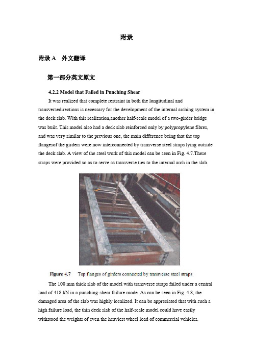
附录附录A 外文翻译第一部分英文原文4.2.2 Model that Failed in Punching ShearIt was realized that complete restraint in both the longitudinal and transversedirections is necessary for the development of the internal arching system in the deck slab. With this realization,another half-scale model of a two-girder bridge was built. This model also had a deck slab reinforced only by polypropylene fibres, and was very similar to the previous one, the main difference being that the top flangesof the girders were now interconnected by transverse steel straps lying outside the deck slab. A view of the steel work of this model can be seen in Fig. 4.7.These straps were provided so as to serve as transverse ties to the internal arch in the slab.The 100 mm thick slab of the model with transverse straps failed under a central load of 418 kN in a punching-shear failure mode. As can be seen in Fig. 4.8, the damaged area of the slab was highly localized. It can be appreciated that with such a high failure load, the thin deck slab of the half-scale model could have easily withstood the weights of even the heaviest wheel load of commercial vehicles.The model tests described above and in sub-section 4.2.1 clearly demonstrate that an internal arching action will indeed develop in a deck slab, but only if it is suitably restrained.4.2.3 Edge StiffeningA further appreciation of the deck slab arching action is provided by tests on a scale model of a skew slab-on-girder bridge. As will be discussed in sub-section 4.4.2, one transverse free edge of the deck slab of this model was stiffened by a composite steel channel with its web in the vertical plane. The other free edge was stiffened by a steel channel diaphragm with its web horizontal and connected to the deck slab through shear connectors. The deck slab near the former transverse edge failed in a mode that was a hybrid between punching shear and flexure. Tests near the composite diaphragm led to failure at a much higher load in punching shear (Bakht and Agarwal, 1993).The above tests confirmed yet again that the presence of the internal arching action in deck slabs induces high in-plane force effects which in turn demand stiffer restraint in the plane of the deck than in the out-of-plane direction.4.3 INTERNALLY RESTRAINED DECK SLABSDeck slabs which require embedded reinforcement for strength will now be referred to as internally restrained deck slabs. The state-of-art up to 1986 relating to the quantification and utilization of the beneficial internal arching action in deck slabs with steel reinforcement has been provided by Bakht and Markovic (1986). Their conclusions complemented with up-to-date information are presented in this chapter in a generally chronological order which, however, cannot be adhered to rigidlybecause of the simultaneous occurrence of some developments.4.3.1 Static Tests on Scale ModelsAbout three decades ago, the Structures Research Office of the Ministry of Transportation of Ontario (MTO), Canada, sponsored an extensive laboratory-based research program into the load carrying capacity of deck slabs; this research program was carried out at Queen's University, Kingston, Ontario. Most of this research was conducted through static tests on scale models of slab-on-girder bridges. This pioneering work is reported by Hewitt and Batchelor (1975) and later by Batchelor et al. (1985), and is summarized in the following.The inability of the concrete to sustain tensile strains, which leads to cracking, has been shown to be the main attribute which causes the compressive membrane forces to develop. This phenomenon is illustrated in Fig. 4.9 (a) which shows the part cross-section of slab-on-girder bridge under the action of a concentrated load.The cracking of the concrete, as shown in the figure, results in a net compressive force near the bottom face of the slab at each of the two girder locations. Midway between the girders, the net compressive force moves towards the top of the slab. It can be readily visualized that the transition of the net compressive force from near the top in the middle region, to near the bottom at the supports corresponds to the familiar arching action. Because of this internal arching action, the failure mode of a deck slab under a concentrated load becomes that of punching shear.If the material of the deck slab has the same stress-strain characteristics in both tension and compression, the slab will not crack and, as shown in Fig. 4.9 (b), will not develop the net compressive force and hence the arching action.In the punching shear type of failure, a frustum separates from the rest of the slab, as shown in schematically in Fig. 4.10. It is noted that in most failure tests, the diameter of the lower end of the frustrum extends to the vicinity of the girders.From analytical and confirmatory laboratory studies, it was established that the most significant factor influencing the failure load of a concrete deck slab is the confinement of the panel under consideration. It was concluded that this confinement is provided by the expanse of the slab beyond the loaded area; its degree was founddifficult to assess analytically. A restraint factor, η, was used as an empirical measure of the confinement; its value is equal to zero for the case of no confinement and 1.0 for full confinement.The effect of various parameters on the failure load can be seen in Table 4.1, which lists the theoretical failure loads for various cases. It can be seen that an increase of the restraint factor from 0.0 to 0.5 results in a very large increase in the failure load. The table also emphasizes the fact that neglect of the restraint factor causes a gross underestimation of the failure load.It was concluded that design for flexure leads to the inclusion of large amounts of unnecessary steel reinforcement in the deck slabs, and that even the minimum amount of steel required for crack control against volumetric changes in concrete is adequate to sustain modern-day, and even future, highway vehicles of North America.It was recommended that for new construction, the reinforcement in a deck slab should be in two layers, with each layer consisting of an orthogonal mesh having the same area of reinforcement in each direction. The area of steel reinforcement in each direction of a mesh was suggested to be 0.2% of the effective area of cross-section of the slab. This empirical method of design was recommended for deck slabs with certain constraints.4.3.2 Pulsating Load Tests on Scale ModelsTo study the fatigue strength of deck slabs with reduced reinforcement, five small scale models with different reinforcement ratios in different panels were tested at the Queen's University at Kingston. Details of this study are reported by Batchelor et al. (1978).Experimental investigation confirmed that for loads normally encountered in North America deck slabs with both conventional and recommended reducedreinforcement have large reserve strengths against failure by fatigue. It was confirmed that the reinforcement in the deck slab should be as noted in sub-section 4.3.1. It is recalled that the 0.2% reinforcement requires that the deck slab must have a minimum restraint factor of 0.5.The work of Okada, et al. (1978) also deals with fatigue tests on full scale models of deck slabs and segments of severely cracked slab removed from eight to ten year old bridges. The application of these test results to deck slabs of actual bridges is open to question because test specimens were removed from the original structures in such a way that they did not retain the confinement necessary for the development of the arching action.4.3.3 Field TestingAlong with the studies described in the preceding sub-section, a program of field testing of the deck slabs of in-service bridges was undertaken by the Structures Research Office of the MTO. The testing consisted of subjecting deck slabs to single concentrated loads, simulating wheel loads, and monitoring the load-deflection characteristics of the slab. The testing is reported by Csagoly et al. (1978) and details of the testing equipment are given by Bakht and Csagoly (1979).Values of the restraint factor, η, were back-calculated from measured deflections.A summary of test results, given in Table 4.2, shows that the average value of η in composite bridges is greater than 0.75, while that for non-composite bridges is 0.42. It was concluded that for new construction, the restraint factor, η, can be assumed to have a minimum value of 0.5.Bakht (1981) reports that after the first application of a test load of high magnitude on deck slabs of existing bridges, a small residual deflection was observed in most cases. Subsequent applications of the same load did not result in further residual deflections. It is postulated that the residual deflections are caused by cracking of the concrete which, as discussed earlier, accompanies the development of the internal arching action. The residual deflections after the first cycle of loading suggest that either the slab was never subjected to loads high enough to cause cracking, or the cracks have 'healed' with time.第二部分汉语翻译4.2.2 在冲切剪应力下的实效模型我们已经知道在桥面板内部拱形系统的形成中,不仅纵向而且横向也被完全约束限制是完全必要的。
桥梁工程本科毕业设计外文翻译---混凝土桥梁的结构形式

本科毕业设计外文翻译混凝土桥梁的结构形式院(系、部)名称:专业名称:学生姓名:学生学号:指导教师:The Structure of Concrete BridgePre-stressed concrete has proved to be technically advantageous, economically competitive, and esthetically superior bridges, from very short span structures using standard components to cable-stayed girders and continuous box girders with clear spans of nearly 100aft .Nearly all concrete bridges, even those of relatively short span, are now pre-stressed. Pre-casting, cast-in-place construction, or a combination of the two methods may be used .Both pre-tensioning and post tensioning are employed, often on the same project.In the United States, highway bridges generally must-meet loading ,design ,and construction requirements of the AASHTO Specification .Design requirements for pedestrian crossings and bridges serving other purposes may be established by local or regional codes and specifications .ACI Code provisions are often incorporated by reference .Bridges spans to about 100ft often consist of pre-cast integral-deck units ,which offer low initial cost ,minimum ,maintenance ,and fast easy construction ,with minimum traffic interruption .Such girders are generally pre-tensioned .The units are placed side by side ,and are often post-tensioned laterally at intermediate diaphragm locations ,after which shear keys between adjacent units are filled with non-shrinking mortar .For highway spans ,an asphalt wearing surface may be applied directly to the top of the pre-cast concrete .In some cases ,a cast-in-place slab is placed to provide composite action .The voided slabs are commonly available in depths from 15 to 21 in .and widths of 3 to 4 ft .For a standard highway HS20 loading, they are suitable for spans to about 50 ft, Standard channel sections are available in depths from 21 to 35 in a variety of widths, and are used for spans between about 20 and 60 ft .The hollow box beams-and single-tee girders are intended for longer spans up to about 100 ft.For medium-span highway bridges ,to about 120 ft ,AASHTO standard I beams are generally used .They are intended for use with a composite cast-in-place roadway slab .Such girders often combine pre-tensioning of the pre-cast member with post-tensioning of the composite beam after the deck is placed .In an effort to obtain improved economy ,some states have adopted more refined designs ,such as the State of Washington standard girders.The specially designed pre-cast girders may be used to carry a monorail transit system .The finished guide way of Walt Disney World Monorail features a series of segments, each consisting of six simply supported pre-tensioned beams ,together to from a continuous structure .Typical spans are 100 to 110 ft . Approximately half of the 337 beams used have some combination of vertical and horizontal curvatures and variable super elevation .Allbeams are hollow, a feature achieved by inserting a styro-foam void in the curved beams and by a moving mandrel in straight beam production.Pre-cast girders may not be used for spans much in excess of 120 ft because of the problems of transporting and erecting large, heavy units.On the other hand ,there is a clear trend toward the use of longer spans for bridges .For elevated urban expressways ,long spans facilitate access and minimize obstruction to activities below .Concern for environmental damage has led to the choice of long spans for continuous viaducts . For river crossings, intermediate piers may be impossible because of requirements of navigational clearance.In typical construction of this type, piers are cast-in-place, often using the slip-forming technique .A “hammerhead” section of box girder is often cast at the top of the pier, and construction proceeds in each direction by the balanced cantilever method. Finally, after the closing cast-in-place joint is made at mid-span, the structure is further post-tensioned for full continuity .Shear keys may be used on the vertical faces between segments, and pre-cast are glued with epoxy resin.The imaginative engineering demonstrated by many special techniques has extended the range of concrete construction for bridges far beyond anything that could be conceived just a few years ago .In the United States, twin curved cast-in –place segmental box girders have recently been completed for of span of 310 ft over the Eel River in northern California .Preliminary design has been completed for twin continuous box girders consisting of central 550 ft spans flanked by 390 ft side spans.Another form of pre-stressed concrete bridge well suited to long spans is the cable-stayed box girder .A notable example is the Chaco-Corrientes Bridge in Argentina .The bridges main span of 804 ft is supported by two A-frame towers, with cable stays stretching from tower tops to points along the deck .The deck itself consists of two parallel box girders made of pre-cast sections erected using the cantilever method .The tensioned cables not only provide a vertical reaction component to support the deck ,but also introduce horizontal compression to the box girders ,adding to the post-tensioning force in those members .Stress-ribbon Bridge pioneered many years ago by the German engineer Ulrich Finsterwalder. The stress-ribbon bridge carries a pipeline and pedestrians over the Rhine River with a span of 446 ft .The superstructure erection sequence was to (a) erect two pairs of cables, (b) place pre-cast slabs forming a sidewalk deck and a U under each of the sets of cables, and (c) cast-in-place concrete within the two Us. The pipeline is placed atop supports at railing height, off to one side, which greatly increases the wind speed of the structure.It is appropriate in discussing bridge forms to mention structural esthetics .The time ispast when structures could be designed on the basis of minimum cost and technical advantages alone .Bridge structures in particular are exposed for all to see .To produce a structure that is visually offensive ,as has occurred all too often in the past, is an act professional irresponsibility .Particularly for major spans ,but also for more ordinary structures ,architectural advice should be sought early in conceptual stage of the design process.混凝土梁桥的结构形式事实证明,预应力混凝土结构是在技术上先进、经济上有竞争力、符合审美学的一种先进技术。
桥梁工程毕业设计外文翻译(箱梁)

西南交通大学本科毕业设计(论文)外文资料翻译年级:学号:姓名:专业:指导老师:2013年 6 月外文资料原文:13Box girders13.1 GeneralThe box girder is the most flexible bridge deck form。
It can cover a range of spans from25 m up to the largest non—suspended concrete decks built, of the order of 300 m。
Single box girders may also carry decks up to 30 m wide。
For the longer span beams, beyond about 50 m,they are practically the only feasible deck section. For the shorter spans they are in competition with most of the other deck types discussed in this book.The advantages of the box form are principally its high structural efficiency (5.4),which minimises the prestress force required to resist a given bending moment,and its great torsional strength with the capacity this gives to re—centre eccentric live loads,minimising the prestress required to carry them。
The box form lends itself to many of the highly productive methods of bridge construction that have been progressively refined over the last 50 years,such as precast segmental construction with or without epoxy resin in the joints,balanced cantilever erection either cast in—situ or coupled with precast segmental construction, and incremental launching (Chapter 15)。
道路桥梁专业 中英文对照---毕业设计论文 外文文献翻译
附录一英文翻译原文AUTOMATIC DEFLECTION AND TEMPERATURE MONITORING OFA BALANCED CANTILEVER CONCRETE BRIDGEby Olivier BURDET, Ph.D.Swiss Federal Institute of Technology, Lausanne, SwitzerlandInstitute of Reinforced and Prestressed Concrete SUMMARYThere is a need for reliable monitoring systems to follow the evolution of the behavior of structures over time.Deflections and rotations are values that reflect the overall structure behavior. This paper presents an innovative approach to the measurement of long-term deformations of bridges by use of inclinometers. High precision electronic inclinometers can be used to follow effectively long-term rotations without disruption of the traffic. In addition to their accuracy, these instruments have proven to be sufficiently stable over time and reliable for field conditions. The Mentue bridges are twin 565 m long box-girder post-tensioned concrete highway bridges under construction in Switzerland. The bridges are built by the balanced cantilever method over a deep valley. The piers are 100 m high and the main span is 150 m. A centralized data acquisition system was installed in one bridge during its construction in 1997. Every minute, the system records the rotation and temperature at a number of measuring points. The simultaneous measurement of rotations and concrete temperature at several locations gives a clear idea of the movements induced by thermal conditions. The system will be used in combination with a hydrostatic leveling setup to follow the long-term behavior of the bridge. Preliminary results show that the system performs reliably and that the accuracy of the sensors is excellent.Comparison of the evolution of rotations and temperature indicate that the structure responds to changes in air temperature rather quickly.1.BACKGROUNDAll over the world, the number of structures in service keeps increasing. With the development of traffic and the increased dependence on reliable transportation, it is becoming more and more necessary to foresee and anticipate the deterioration of structures. In particular,for structures that are part of major transportation systems, rehabilitation works need to be carefully planned in order to minimize disruptions of traffic. Automatic monitoring of structures is thus rapidly developing.Long-term monitoring of bridges is an important part of this overall effort to attempt to minimize both the impact and the cost of maintenance and rehabilitation work of major structures. By knowing the rate of deterioration of a given structure, the engineer is able to anticipate and adequately define the timing of required interventions. Conversely, interventions can be delayed until the condition of the structure requires them, without reducing the overall safety of the structure.The paper presents an innovative approach to the measurement of long-term bridge deformations. The use of high precision inclinometers permits an effective, accurate and unobtrusive following of the long-term rotations. The measurements can be performed under traffic conditions. Simultaneous measurement of the temperature at several locations gives a clear idea of the movements induced by thermal conditions and those induced by creep and shrinkage. The system presented is operational since August 1997 in the Mentue bridge, currently under construction in Switzerland. The structure has a main span of 150 m and piers 100 m high.2. LONG-TERM MONITORING OF BRIDGESAs part of its research and service activities within the Swiss Federal Institute of Technology in Lausanne (EPFL), IBAP - Reinforced and Prestressed Concrete has been involved in the monitoring of long-time deformations of bridges and other structures for over twenty-five years [1, 2, 3, 4]. In the past, IBAP has developed a system for the measurement of long-term deformations using hydrostatic leveling [5, 6]. This system has been in successful service in ten bridges in Switzerland for approximately ten years [5,7]. The system is robust, reliable and sufficiently accurate, but it requires human intervention for each measurement, and is not well suited for automatic data acquisition. One additional disadvantage of this system is that it is only easily applicable to box girder bridges with an accessible box.Occasional continuous measurements over periods of 24 hours have shown that the amplitude of daily movements is significant, usually amounting to several millimeters over a couple of hours. This is exemplified in figure 1, where measurements of the twin Lutrive bridges, taken over a period of several years before and after they were strengthened by post-tensioning, areshown along with measurements performed over a period of 24 hours. The scatter observed in the data is primarily caused by thermal effects on the bridges. In the case of these box-girder bridges built by the balanced cantilever method, with a main span of 143.5 m, the amplitude of deformations on a sunny day is of the same order of magnitude than the long term deformation over several years.Instantaneous measurements, as those made by hydrostatic leveling, are not necessarily representative of the mean position of the bridge. This occurs because the position of the bridge at the time of the measurement is influenced by the temperature history over the past several hours and days. Even if every care was taken to perform the measurements early in the morning and at the same period every year, it took a relatively long time before it was realized that the retrofit performed on the Lutrive bridges in 1988 by additional post-tensioning [3, 7,11] had not had the same effect on both of them.Figure 1: Long-term deflections of the Lutrive bridges, compared to deflections measured in a 24-hour period Automatic data acquisition, allowing frequent measurements to be performed at an acceptable cost, is thus highly desirable. A study of possible solutions including laser-based leveling, fiber optics sensors and GPS-positioning was performed, with the conclusion that, provided that their long-term stability can be demonstrated, current types of electronic inclinometers are suitable for automatic measurements of rotations in existing bridges [8].3. MENTUE BRIDGESThe Mentue bridges are twin box-girder bridges that will carry the future A1 motorway from Lausanne to Bern. Each bridge, similar in design, has an overall length of approximately 565 m, and a width of 13.46 m, designed to carry two lanes of traffic and an emergency lane. The bridges cross a deep valley with steep sides (fig. 2). The balanced cantilever design results from a bridge competition. The 100 m high concrete piers were built using climbing formwork, after which the construction of the balanced cantilever started (fig. 3).4. INCLINOMETERSStarting in 1995, IBAP initiated a research project with the goal of investigating the feasibility of a measurement system using inclinometers. Preliminary results indicated that inclinometers offer several advantages for the automatic monitoring of structures. Table 1 summarizes the main properties of the inclinometers selected for this study.One interesting property of measuring a structure’s rotations, is that, for a given ratio of maximum deflection to span length, the maximum rotation is essentially independent from its static system [8]. Since maximal allowable values of about 1/1,000 for long-term deflections under permanent loads are generally accepted values worldwide, developments made for box-girder bridges with long spans, as is the case for this research, are applicable to other bridges, for instance bridges with shorter spans and other types of cross-sections. This is significant because of the need to monitor smaller spans which constitute the majority of all bridges.The selected inclinometers are of type Wyler Zerotronic ±1°[9]. Their accuracy is 1 microradian (μrad), which corresponds to a rotation of one millimeter per kilometer, a very small value. For an intermediate span of a continuous beam with a constant depth, a mid-span deflection of 1/20,000 would induce a maximum rotation of about 150 μrad, or 0.15 milliradians (mrad).One potential problem with electronic instruments is that their measurements may drift overtime. To quantify and control this problem, a mechanical device was designed allowing the inclinometers to be precisely rotated of 180° in an horizontal plane (fig. 4). The drift of each inclinometer can be very simply obtained by comparing the values obtained in the initial and rotated position with previously obtained values. So far, it has been observed that the type of inclinometer used in this project is not very sensitive to drifting.5. INSTRUMENTATION OF THE MENTUE BRIDGESBecause a number of bridges built by the balanced cantilever method have shown an unsatisfactory behavior in service [2, 7,10], it was decided to carefully monitor the evolution of the deformations of the Mentue bridges. These bridges were designed taking into consideration recent recommendations for the choice of the amount of posttensioning [7,10,13]. Monitoring starting during the construction in 1997 and will be pursued after the bridges are opened to traffic in 2001. Deflection monitoring includes topographic leveling by the highway authorities, an hydrostatic leveling system over the entire length of both bridges and a network of inclinometers in the main span of the North bridge. Data collection iscoordinated by the engineer of record, to facilitate comparison of measured values. The information gained from these observations will be used to further enhance the design criteria for that type of bridge, especially with regard to the amount of post-tensioning [7, 10, 11, 12, 13].The automatic monitoring system is driven by a data acquisition program that gathers and stores the data. This system is able to control various types of sensors simultaneously, at the present time inclinometers and thermal sensors. The computer program driving all the instrumentation offers a flexible framework, allowing the later addition of new sensors or data acquisition systems. The use of the development environment LabView [14] allowed to leverage the large user base in the field of laboratory instrumentation and data analysis. The data acquisition system runs on a rather modest computer, with an Intel 486/66 Mhz processor, 16 MB of memory and a 500 MB hard disk, running Windows NT. All sensor data are gathered once per minute and stored in compressed form on the hard disk. The system is located in the box-girder on top of pier 3 (fig. 5). It can withstand severe weather conditions and will restart itself automatically after a power outage, which happened frequently during construction.6. SENSORSFigure 5(a) shows the location of the inclinometers in the main span of the North bridge. The sensors are placed at the axis of the supports (①an d⑤), at 1/4 and 3/4 (③an d④) of the span and at 1/8 of the span for②. In the cross section, the sensors are located on the North web, at a height corresponding to the center of gravity of the section (fig.5a). The sensors are all connected by a single RS-485 cable to the central data acquisition system located in the vicinity of inclinometer ①. Monitoring of the bridge started already during its construction. Inclinometers①,②and③were installed before the span was completed. The resulting measurement were difficult to interpret, however, because of the wide variations of angles induced by the various stages of this particular method of construction.The deflected shape will be determined by integrating the measured rotations along the length of the bridge (fig.5b). Although this integration is in principle straightforward, it has been shown [8, 16] that the type of loading and possible measurement errors need to be carefully taken into account.Thermal sensors were embedded in concrete so that temperature effects could be taken into account for the adjustment of the geometry of the formwork for subsequent casts. Figure 6 shows the layout of thermal sensors in the main span. The measurement sections are located at the same sections than the inclinometers (fig. 5). All sensors were placed in the formwork before concreting and were operational as soon as the formwork was removed, which was required for the needs of the construction. In each section, seven of the nine thermal sensor (indicated in solid black in fig. 6) are now automatically measured by the central data acquisition system.7. RESULTSFigure 7 shows the results of inclinometry measurements performed from the end ofSeptember to the third week of November 1997. All inclinometers performed well during that period. Occasional interruptions of measurement, as observed for example in early October are due to interruption of power to the system during construction operations. The overall symmetry of results from inclinometers seem to indicate that the instruments drift is not significant for that time period. The maximum amplitude of bridge deflection during the observed period, estimated on the basis of the inclinometers results, is around 40 mm. More accurate values will be computed when the method of determination ofdeflections will have been further calibrated with other measurements. Several periods of increase, respectively decrease, of deflections over several days can be observed in the graph. This further illustrates the need for continuous deformation monitoring to account for such effects. The measurement period was .busy. in terms of construction, and included the following operations: the final concrete pours in that span, horizontal jacking of the bridge to compensate some pier eccentricities, as well as the stressing of the continuity post-tensioning, and the de-tensioning of the guy cables (fig. 3). As a consequence, the interpretation of these measurements is quite difficult. It is expected that further measurements, made after the completion of the bridge, will be simpler to interpret.Figure 8 shows a detail of the measurements made in November, while figure.9 shows temperature measurements at the top and bottom of the section at mid-span made during that same period. It is clear that the measured deflections correspond to changes in the temperature. The temperature at the bottom of the section follows closely variations of the air temperature(measured in the shade near the north web of the girder). On the other hand, the temperature at the top of the cross section is less subject to rapid variations. This may be due to the high elevation of the bridge above ground, and also to the fact that, during the measuring period, there was little direct sunshine on the deck. The temperature gradient between top and bottom of the cross section has a direct relationship with short-term variations. It does not, however, appear to be related to the general tendency to decrease in rotations observed in fig. 8.8. FUTURE DEVELOPMENTSFuture developments will include algorithms to reconstruct deflections from measured rotations. To enhance the accuracy of the reconstruction of deflections, a 3D finite element model of the entire structure is in preparation [15]. This model will be used to identify the influence on rotations of various phenomena, such as creep of the piers and girder, differential settlements, horizontal and vertical temperature gradients or traffic loads.Much work will be devoted to the interpretation of the data gathered in the Mentue bridge. The final part of the research project work will focus on two aspects: understanding the very complex behavior of the structure, and determining the most important parameters, to allow a simple and effective monitoring of the bridges deflections.Finally, the research report will propose guidelines for determination of deflections from measured rotations and practical recommendations for the implementation of measurement systems using inclinometers. It is expected that within the coming year new sites will be equipped with inclinometers. Experiences made by using inclinometers to measure deflections during loading tests [16, 17] have shown that the method is very flexible and competitive with other high-tech methods.As an extension to the current research project, an innovative system for the measurement of bridge joint movement is being developed. This system integrates easily with the existing monitoring system, because it also uses inclinometers, although from a slightly different type.9. CONCLUSIONSAn innovative measurement system for deformations of structures using high precision inclinometers has been developed. This system combines a high accuracy with a relatively simple implementation. Preliminary results are very encouraging and indicate that the use of inclinometers to monitor bridge deformations is a feasible and offers advantages. The system is reliable, does not obstruct construction work or traffic and is very easily installed. Simultaneous temperature measurements have confirmed the importance of temperature variations on the behavior of structural concrete bridges.10. REFERENCES[1] ANDREY D., Maintenance des ouvrages d’art: méthodologie de surveillance, PhD Dissertation Nr 679, EPFL, Lausanne, Switzerland, 1987.[2] BURDET O., Load Testing and Monitoring of Swiss Bridges, CEB Information Bulletin Nr 219, Safety and Performance Concepts, Lausanne, Switzerland, 1993.[3] BURDET O., Critères pour le choix de la quantitéde précontrainte découlant de l.observation de ponts existants, CUST-COS 96, Clermont-Ferrand, France, 1996.[4] HASSAN M., BURDET O., FAVRE R., Combination of Ultrasonic Measurements and Load Tests in Bridge Evaluation, 5th International Conference on Structural Faults and Repair, Edinburgh, Scotland, UK, 1993.[5] FAVRE R., CHARIF H., MARKEY I., Observation à long terme de la déformation des ponts, Mandat de Recherche de l’OFR 86/88, Final Report, EPFL, Lausanne, Switzerland, 1990.[6] FAVRE R., MARKEY I., Long-term Monitoring of Bridge Deformation, NATO Research Workshop, Bridge Evaluation, Repair and Rehabilitation, NATO ASI series E: vol. 187, pp. 85-100, Baltimore, USA, 1990.[7] FAVRE R., BURDET O. et al., Enseignements tirés d’essais de charge et d’observations à long terme pour l’évaluation des ponts et le choix de la précontrainte, OFR Report, 83/90, Zürich, Switzerland, 1995.[8] DAVERIO R., Mesures des déformations des ponts par un système d’inclinométrie,Rapport de maîtrise EPFL-IBAP, Lausanne, Switzerland, 1995.[9] WYLER AG., Technical specifications for Zerotronic Inclinometers, Winterthur, Switzerland, 1996.[10] FAVRE R., MARKEY I., Generalization of the Load Balancing Method, 12th FIP Congress, Prestressed Concrete in Switzerland, pp. 32-37, Washington, USA, 1994.[11] FAVRE R., BURDET O., CHARIF H., Critères pour le choix d’une précontrainte: application au cas d’un renforcement, "Colloque International Gestion des Ouvrages d’Art: Quelle Stratégie pour Maintenir et Adapter le Patrimoine, pp. 197-208, Paris, France, 1994. [12] FAVRE R., BURDET O., Wahl einer geeigneten Vorspannung, Beton- und Stahlbetonbau, Beton- und Stahlbetonbau, 92/3, 67, Germany, 1997.[13] FAVRE R., BURDET O., Choix d’une quantité appropriée de précontrain te, SIA D0 129, Zürich, Switzerland, 1996.[14] NATIONAL INSTRUMENTS, LabView User.s Manual, Austin, USA, 1996.[15] BOUBERGUIG A., ROSSIER S., FAVRE R. et al, Calcul non linéaire du béton arméet précontraint, Revue Français du Génie Civil, vol. 1 n° 3, Hermes, Paris, France, 1997. [16] FEST E., Système de mesure par inclinométrie: développement d’un algorithme de calcul des flèches, Mémoire de maîtrise de DEA, Lausanne / Paris, Switzerland / France, 1997.[17] PERREGAUX N. et al., Vertical Displacement of Bridges using the SOFO System: a Fiber Optic Monitoring Method for Structures, 12th ASCE Engineering Mechanics Conference, San Diego, USA, to be published,1998.译文平衡悬臂施工混凝土桥挠度和温度的自动监测作者Olivier BURDET博士瑞士联邦理工学院,洛桑,瑞士钢筋和预应力混凝土研究所概要:我们想要跟踪结构行为随时间的演化,需要一种可靠的监测系统。
(完整版)桥梁毕业设计外文翻译
外文资料The Tenth East Asia-Pacific Conference on Structural Engineering and ConstructionAugust 3-5, 2006, Bangkok, ThailandStructural Rehabilitation of Concrete Bridges with CFRPComposites-Practical Details and ApplicationsRiyad S. ABOUTAHA1, and Nuttawat CHUTARAT2 ABSTRACT: Many old existing bridges are still active in the various highway transportation networks, carrying heavier and faster trucks, in all kinds of environments. Water, salt, and wind have caused damage to these old bridges, and scarcity of maintenance funds has aggravated their conditions. One attempt to restore the original condition; and to extend the service life of concrete bridges is by the use of carbon fiber reinforced polymer (CFRP) composites. There appear to be very limited guides on repair of deteriorated concrete bridges with CFRP composites. In this paper, guidelines for nondestructive evaluation (NDE), nondestructive testing (NDT), and rehabilitation of deteriorated concrete bridges with CFRP composites are presented. The effect of detailing on ductility and behavior of CFRP strengthened concrete bridges are also discussed and presented.KEYWORDS: Concrete deterioration, corrosion of steel, bridge rehabilitation, CFRP composites.1 IntroductionThere are several destructive external environmental factors that limit the service life of bridges. These factors include but not limited to chemical attacks, corrosion of reinforcing steel bars, carbonation of concrete, and chemical reaction of aggregate. If bridges were not well maintained, these factors may lead to a structural deficiency, which reduces the margin of safety, and may result in structural failure. In order to rehabilitate and/or strengthen deteriorated existing bridges, thorough evaluation should be conducted. The purpose of the evaluation is to assess the actual condition of any existing bridge, and generally to examine the remaining strength and load carry capacity of the bridge.1 Associate Professor, Syracuse University, U.S.A.2 Lecturer, Sripatum University, Thailand.One attempt to restore the original condition, and to extend the service life of concrete bridges is by the use of carbon fiber reinforced polymer (CFRP) composites.In North America, Europe and Japan, CFRP has been extensively investigated and applied. Several design guides have been developed for strengthening of concrete bridges with CFRP composites. However, there appear to be very limited guides on repair of deteriorated concrete bridges with CFRP composites. This paper presents guidelines for repair of deteriorated concrete bridges, along with proper detailing. Evaluation, nondestructive testing, and rehabilitation of deteriorated concrete bridges with CFRP composites are presented. Successful application of CFRP composites requires good detailing as the forces developed in the CFRP sheets are transferred by bond at the concrete-CFRP interface. The effect of detailing on ductility and behavior of CFRP strengthened concrete bridges will also be discussed and presented.2 Deteriorated Concrete BridgesDurability of bridges is of major concern. Increasing number of bridges are experiencing significant amounts of deterioration prior to reaching their design service life. This premature deterioration considered a problem in terms of the structural integrity and safety of the bridge. In addition, deterioration of a bridge has a considerable magnitude of costs associated with it. In many cases, the root of a deterioration problem is caused by corrosion of steel reinforcement in concrete structures. Concrete normally acts to provide a high degree of protection against corrosion of the embedded reinforcement. However, corrosion will result in those cases that typically experience poor concrete quality, inadequate design or construction, and harsh environmental conditions. If not treated a durability problem, e.g. corrosion, may turn into a strength problem leading to a structural deficiency, as shown in Figure1.Figure1 Corrosion of the steel bars is leading to a structural deficiency3 Non-destructive Testing of Deteriorated Concrete Bridge PiersIn order to design a successful retrofit system, the condition of the existing bridge should be thoroughly evaluated. Evaluation of existing bridge elements or systems involves review of the asbuilt drawings, as well as accurate estimate of the condition of the existing bridge, as shown in Figure2. Depending on the purpose of evaluation, non-destructive tests may involve estimation of strength, salt contents, corrosion rates, alkalinity in concrete, etc.Figure2 Visible concrete distress marked on an elevation of a concrete bridge pier Although most of the non-destructive tests do not cause any damage to existing bridges, some NDT may cause minor local damage (e.g. drilled holes & coring) that should be repaired right after the NDT. These tests are also referred to as partial destructive tests but fall under non-destructive testing.In order to select the most appropriate non-destructive test for a particular case, thepurpose of the test should be identified. In general, there are three types of NDT to investigate: (1) strength, (2) other structural properties, and (3) quality and durability. The strength methods may include; compressive test (e.g. core test/rebound hammer/ ultrasonic pulse velocity), surface hardness test (e.g. rebound hammer), penetration test (e.g. Windsor probe), and pullout test (anchor test).Other structural test methods may include; concrete cover thickness (cover-meter), locating rebars (rebar locator), rebar size (some rebar locators/rebar data scan), concrete moisture (acquameter/moisture meter), cracking (visual test/impact echo/ultrasonic pulse velocity), delamination (hammer test/ ultrasonic pulse velocity/impact echo), flaws and internal cracking (ultrasonic pulse velocity/impact echo), dynamic modulus of elasticity (ultrasonic pulse velocity), Possion’s ratio (ultrasonic pulse velocity), thickness of concrete slab or wall (ultrasonic pulse velocity), CFRP debonding (hammer test/infrared thermographic technique), and stain on concrete surface (visual inspection).Quality and durability test methods may include; rebar corrosion rate –field test, chloride profile field test, rebar corrosion analysis, rebar resistivity test, alkali-silica reactivity field test, concrete alkalinity test (carbonation field test), concrete permeability (field test for permeability).4 Non-destructive Evaluation of Deteriorated Concrete Bridge PiersThe process of evaluating the structural condition of an existing concrete bridge consists of collecting information, e.g. drawings and construction & inspection records, analyzing NDT data, and structural analysis of the bridge. The evaluation process can be summarized as follows: (1) Planning for the assessment, (2) Preliminary assessment, which involves examination of available documents, site inspection, materials assessment, and preliminary analysis, (3) Preliminary evaluation, this involves: examination phase, and judgmental phase, and finally (4) the cost-impact study.If the information is insufficient to conduct evaluation to a specific required level, then a detailed evaluation may be conducted following similar steps for the above-mentioned preliminary assessment, but in-depth assessment. Successful analytical evaluation of an existing deteriorated concrete bridge should consider the actual condition of the bridge and level of deterioration of various elements. Factors, e.g. actual concrete strength, level of damage/deterioration, actual size of corroded rebars, loss of bond between steel and concrete, etc. should be modeled into a detailed analysis. If such detailed analysis is difficult to accomplish within a reasonable period of time, thenevaluation by field load testing of the actual bridge in question may be required.5 Bridge Rehabilitation with CFRP CompositesApplication of CFRP composite materials is becoming increasingly attractive to extend the service life of existing concrete bridges. The technology of strengthening existing bridges with externally bonded CFRP composites was developed primarily in Japan (FRP sheets), and Europe (laminates). The use of these materials for strengthening existing concrete bridges started in the 1980s, first as a substitute to bonded steel plates, and then as a substitute for steel jackets for seismic retrofit of bridge columns. CFRP Composite materials are composed of fiber reinforcement bonded together with a resin matrix. The fibers provide the composite with its unique structural properties. The resin matrix supports the fibers, protect them, and transfer the applied load to the fibers through shearing stresses. Most of the commercially available CFRP systems in the construction market consist of uniaxial fibers embedded in a resin matrix, typically epoxy. Carbon fibers have limited ultimate strain, which may limit the deformability of strengthened members. However, under traffic loads, local debonding between FRP sheets and concrete substrate would allow for acceptable level of global deformations before failure.CFRP composites could be used to increase the flexural and shear strength of bridge girders including pier cap beams, as shown in Figure3. In order to increase the ductility of CFRP strengthened concrete girders, the longitudinal CFRP composite sheets used for flexural strengthening should be anchored with transverse/diagonal CFRP anchors to prevent premature delamination of the longitudinal sheets due to localized debonding at the concrete surface-CFRP sheet interface. In order to prevent stress concentration and premature fracture of the CFRP sheets at the corners of concrete members, the corners should be rounded at 50mm (2.0 inch) radius, as shown in Figure3.Deterioration of concrete bridge members due to corrosion of steel bars usually leads in loss of steel section and delamination of concrete cover. As a result, such deterioration may lead to structural deficiency that requires immediate attention. Figure4 shows rehabilitation of structurally deficient concrete bridge pier using CFRP composites.Figure3 Flexural and shear strengthening of concrete bridge pier with FRP compositesFigure4 Rehabilitation of deteriorated concrete bridge pier with CFRP composites6 Summary and ConclusionsEvaluation, non-destructive testing and rehabilitation of deteriorated concrete bridges were presented. Deterioration of concrete bridge components due to corrosion may lead to structural deficiencies, e.g. flexural and/or shear failures. Application of CFRP composite materials is becoming increasingly attractive solution to extend the service life of existing concrete bridges. CFRP composites could be utilized for flexural and shear strengthening, as well as for restoration of deteriorated concrete bridge components. The CFRP composite sheets should be well detailed to prevent stress concentration and premature fracture or delamination. For successful rehabilitation of concrete bridges in corrosive environments, a corrosion protection system should be used along with the CFRP system.第十届东亚太结构工程设计与施工会议2006年8月3-5号,曼谷,泰国碳纤维复合材料修复混凝土桥梁结构的详述及应用Riyad S. ABOUTAHA1, and Nuttawat CHUTARAT2摘要:在各式各样的公路交通网络中,许多现有的古老桥梁,在各种恶劣的环境下,如更重的荷载和更快的车辆等条件下,依然在被使用着。
桥梁工程毕业论文英文
桥梁工程毕业论文英文Title: Analysis and Design of Bridge StructuresAbstract:Bridge engineering is an integral part of civil engineering and plays a crucial role in connecting communities and facilitating transportation. The purpose of this thesis is to analyze and design bridge structures, focusing on key components such as foundations, superstructures, and substructures. The analysis includes evaluating the structural behavior and load carrying capacity through the utilization of various analytical tools. Furthermore, the design phase encompasses selecting suitable materials and designing components to meet safety and durability requirements. The study serves as a comprehensive guide to understanding the principles and processes involved in bridge engineering.1. IntroductionBridges are vital infrastructure that connects people, places, and economies. The study of bridge engineering involves the application of core principles like physics, materials science, and mathematics todesign and construct safe and efficient bridge structures. This thesis aims to provide an overview of the analysis and design principles involved in bridge engineering.2. Structural AnalysisThe analysis of bridge structures is crucial to ensure their safety and functionality. This chapter presents various analytical techniques for evaluating bridge behavior. The use of finite element analysis, structural modeling, and computer-aided design software is discussed in detail. Different load types and load combinations are also considered to determine the resilience and load carrying capacity of the bridge.3. Foundation DesignThe foundation is a critical component of any bridge structure, as it transfers the loads from the superstructure to the underlying ground. This chapter explores various foundation types, such as shallow foundations, deep foundations, and pile foundations. Design considerations, including soil mechanics, bearing capacity, settlement analysis, and groundwater conditions, are discussed. The use ofgeotechnical engineering software to simulate and optimize foundation design is also explored.4. Superstructure DesignThe superstructure refers to the portion of the bridge that supports the traffic loads and transfers them to the substructure. This chapter discusses the different types of superstructures, including beam bridges, truss bridges, and arch bridges. The selection of materials, such as concrete, steel, and composite materials, is analyzed based on their structural properties and cost-effectiveness. The design process incorporates the calculation of load distribution, structural stability, and deflection limits.5. Substructure DesignThe substructure comprises the bridge piers, abutments, and retaining walls, which provide support to the superstructure. This chapter focuses on the design considerations for substructures, including the selection of suitable materials, analysis of load distribution, and evaluation of stability against various forces and environmental conditions. Design principles for reinforced concrete and masonry substructures are explored, along with mitigationstrategies for potential issues such as scour and seismic activity.6. Safety and DurabilityEnsuring safety and durability is of utmost importance in bridge engineering. This chapter discusses the necessary steps for evaluating the safety of bridge structures, including factor of safety calculations, failure mode analysis, and risk assessment procedures. The discussion also includes guidelines for maintenance and inspection to ensure long-term performance and durability.7. ConclusionThis thesis provides an in-depth analysis and design framework for bridge structures. By comprehensively exploring the key components of bridges, including foundations, superstructures, and substructures, it provides valuable insights into the principles and processes involved in bridge engineering. The knowledge gained from this study will contribute to the safe and efficient design and construction of future bridge projects.。
道路与桥梁工程中英文对照外文翻译文献

中英文对照外文翻译(文档含英文原文和中文翻译)Bridge research in EuropeA brief outline is given of the development of the European Union, together with the research platform in Europe. The special case of post-tensioned bridges in the UK is discussed. In order to illustrate the type of European research being undertaken, an example is given from the University of Edinburgh portfolio: relating to the identification of voids in post-tensioned concrete bridges using digital impulse radar.IntroductionThe challenge in any research arena is to harness the findings of different research groups to identify a coherent mass of data, which enables research and practice to be better focused. A particular challenge exists with respect to Europe where language barriers are inevitably very significant. The European Community was formed in the 1960s based upon a political will within continental Europe to avoid the European civil wars, which developed into World War 2 from 1939 to 1945. The strong political motivation formed the original community of which Britain was not a member. Many of the continental countries saw Britain’s interest as being purelyeconomic. The 1970s saw Britain joining what was then the European Economic Community (EEC) and the 1990s has seen the widening of the community to a European Union, EU, with certain political goals together with the objective of a common European currency.Notwithstanding these financial and political developments, civil engineering and bridge engineering in particular have found great difficulty in forming any kind of common thread. Indeed the educational systems for University training are quite different between Britain and the European continental countries. The formation of the EU funding schemes —e.g. Socrates, Brite Euram and other programs have helped significantly. The Socrates scheme is based upon the exchange of students between Universities in different member states. The Brite Euram scheme has involved technical research grants given to consortia of academics and industrial partners within a number of the states— a Brite Euram bid would normally be led by an industrialist.In terms of dissemination of knowledge, two quite different strands appear to have emerged. The UK and the USA have concentrated primarily upon disseminating basic research in refereed journal publications: ASCE, ICE and other journals. Whereas the continental Europeans have frequently disseminated basic research at conferences where the circulation of the proceedings is restricted.Additionally, language barriers have proved to be very difficult to break down. In countries where English is a strong second language there has been enthusiastic participation in international conferences based within continental Europe —e.g. Germany, Italy, Belgium, The Netherlands and Switzerland. However, countries where English is not a strong second language have been hesitant participants }—e.g. France.European researchExamples of research relating to bridges in Europe can be divided into three types of structure:Masonry arch bridgesBritain has the largest stock of masonry arch bridges. In certain regions of the UK up to 60% of the road bridges are historic stone masonry arch bridges originally constructed for horse drawn traffic. This is less common in other parts of Europe as many of these bridges were destroyed during World War 2.Concrete bridgesA large stock of concrete bridges was constructed during the 1950s, 1960s and 1970s. At the time, these structures were seen as maintenance free. Europe also has a large number of post-tensioned concrete bridges with steel tendon ducts preventing radar inspection. This is a particular problem in France and the UK.Steel bridgesSteel bridges went out of fashion in the UK due to their need for maintenance as perceived in the 1960s and 1970s. However, they have been used for long span and rail bridges, and they are now returning to fashion for motorway widening schemes in the UK.Research activity in EuropeIt gives an indication certain areas of expertise and work being undertaken in Europe, but is by no means exhaustive.In order to illustrate the type of European research being undertaken, an example is given from the University of Edinburgh portfolio. The example relates to the identification of voids in post-tensioned concrete bridges, using digital impulse radar.Post-tensioned concrete rail bridge analysisOve Arup and Partners carried out an inspection and assessment of the superstructure of a 160 m long post-tensioned, segmental railway bridge in Manchester to determine its load-carrying capacity prior to a transfer of ownership, for use in the Metrolink light rail system..Particular attention was paid to the integrity of its post-tensioned steel elements. Physical inspection, non-destructive radar testing and other exploratory methods were used to investigate for possible weaknesses in the bridge.Since the sudden collapse of Ynys-y-Gwas Bridge in Wales, UK in 1985, there has been concern about the long-term integrity of segmental, post-tensioned concrete bridges which may b e prone to ‘brittle’ failure without warning. The corrosion protection of the post-tensioned steel cables, where they pass through joints between the segments, has been identified as a major factor affecting the long-term durability and consequent strength of this type of bridge. The identification of voids in grouted tendon ducts at vulnerable positions is recognized as an important step in the detection of such corrosion.Description of bridgeGeneral arrangementBesses o’ th’ Barn Bridge is a 160 m long, three span, segmental, post-tensionedconcrete railway bridge built in 1969. The main span of 90 m crosses over both the M62 motorway and A665 Bury to Prestwick Road. Minimum headroom is 5.18 m from the A665 and the M62 is cleared by approx 12.5 m.The superstructure consists of a central hollow trapezoidal concrete box section 6.7 m high and 4 m wide. The majority of the south and central spans are constructed using 1.27 m long pre-cast concrete trapezoidal box units, post-tensioned together. This box section supports the in site concrete transverse cantilever slabs at bottom flange level, which carry the rail tracks and ballast.The center and south span sections are of post-tensioned construction. These post-tensioned sections have five types of pre-stressing:1. Longitudinal tendons in grouted ducts within the top and bottom flanges.2. Longitudinal internal draped tendons located alongside the webs. These are deflected at internal diaphragm positions and are encased in in site concrete.3. Longitudinal macalloy bars in the transverse cantilever slabs in the central span .4. Vertical macalloy bars in the 229 mm wide webs to enhance shear capacity.5. Transverse macalloy bars through the bottom flange to support the transverse cantilever slabs.Segmental constructionThe pre-cast segmental system of construction used for the south and center span sections was an alternative method proposed by the contractor. Current thinking suggests that such a form of construction can lead to ‘brittle’ failure of the ent ire structure without warning due to corrosion of tendons across a construction joint,The original design concept had been for in site concrete construction.Inspection and assessmentInspectionInspection work was undertaken in a number of phases and was linked with the testing required for the structure. The initial inspections recorded a number of visible problems including:Defective waterproofing on the exposed surface of the top flange.Water trapped in the internal space of the hollow box with depths up to 300 mm.Various drainage problems at joints and abutments.Longitudinal cracking of the exposed soffit of the central span.Longitudinal cracking on sides of the top flange of the pre-stressed sections.Widespread sapling on some in site concrete surfaces with exposed rusting reinforcement.AssessmentThe subject of an earlier paper, the objectives of the assessment were:Estimate the present load-carrying capacity.Identify any structural deficiencies in the original design.Determine reasons for existing problems identified by the inspection.Conclusion to the inspection and assessmentFollowing the inspection and the analytical assessment one major element of doubt still existed. This concerned the condition of the embedded pre-stressing wires, strands, cables or bars. For the purpose of structural analysis these elements、had been assumed to be sound. However, due to the very high forces involved,、a risk to the structure, caused by corrosion to these primary elements, was identified.The initial recommendations which completed the first phase of the assessment were:1. Carry out detailed material testing to determine the condition of hidden structural elements, in particularthe grouted post-tensioned steel cables.2. Conduct concrete durability tests.3. Undertake repairs to defective waterproofing and surface defects in concrete.Testing proceduresNon-destructi v e radar testingDuring the first phase investigation at a joint between pre-cast deck segments the observation of a void in a post-tensioned cable duct gave rise to serious concern about corrosion and the integrity of the pre-stress. However, the extent of this problem was extremely difficult to determine. The bridge contains 93 joints with an average of 24 cables passing through each joint, i.e. there were approx. 2200 positions where investigations could be carried out. A typical section through such a joint is that the 24 draped tendons within the spine did not give rise to concern because these were protected by in site concrete poured without joints after the cables had been stressed.As it was clearly impractical to consider physically exposing all tendon/joint intersections, radar was used to investigate a large numbers of tendons and hence locate duct voids within a modest timescale. It was fortunate that the corrugated steel ducts around the tendons were discontinuous through the joints which allowed theradar to detect the tendons and voids. The problem, however, was still highly complex due to the high density of other steel elements which could interfere with the radar signals and the fact that the area of interest was at most 102 mm wide and embedded between 150 mm and 800 mm deep in thick concrete slabs.Trial radar investigations.Three companies were invited to visit the bridge and conduct a trial investigation. One company decided not to proceed. The remaining two were given 2 weeks to mobilize, test and report. Their results were then compared with physical explorations.To make the comparisons, observation holes were drilled vertically downwards into the ducts at a selection of 10 locations which included several where voids were predicted and several where the ducts were predicted to be fully grouted. A 25-mm diameter hole was required in order to facilitate use of the chosen horoscope. The results from the University of Edinburgh yielded an accuracy of around 60%.Main radar sur v ey, horoscope verification of v oids.Having completed a radar survey of the total structure, a baroscopic was then used to investigate all predicted voids and in more than 60% of cases this gave a clear confirmation of the radar findings. In several other cases some evidence of honeycombing in the in site stitch concrete above the duct was found.When viewing voids through the baroscopic, however, it proved impossible to determine their actual size or how far they extended along the tendon ducts although they only appeared to occupy less than the top 25% of the duct diameter. Most of these voids, in fact, were smaller than the diameter of the flexible baroscopic being used (approximately 9 mm) and were seen between the horizontal top surface of the grout and the curved upper limit of the duct. In a very few cases the tops of the pre-stressing strands were visible above the grout but no sign of any trapped water was seen. It was not possible, using the baroscopic, to see whether those cables were corroded.Digital radar testingThe test method involved exciting the joints using radio frequency radar antenna: 1 GHz, 900 MHz and 500 MHz. The highest frequency gives the highest resolution but has shallow depth penetration in the concrete. The lowest frequency gives the greatest depth penetration but yields lower resolution.The data collected on the radar sweeps were recorded on a GSSI SIR System 10.This system involves radar pulsing and recording. The data from the antenna is transformed from an analogue signal to a digital signal using a 16-bit analogue digital converter giving a very high resolution for subsequent data processing. The data is displayed on site on a high-resolution color monitor. Following visual inspection it is then stored digitally on a 2.3-gigabyte tape for subsequent analysis and signal processing. The tape first of all records a ‘header’ noting the digital radar settings together with the trace number prior to recording the actual data. When the data is played back, one is able to clearly identify all the relevant settings —making for accurate and reliable data reproduction.At particular locations along the traces, the trace was marked using a marker switch on the recording unit or the antenna.All the digital records were subsequently downloaded at the University’s NDT laboratory on to a micro-computer.(The raw data prior to processing consumed 35 megabytes of digital data.)Post-processing was undertaken using sophisticated signal processing software. Techniques available for the analysis include changing the color transform and changing the scales from linear to a skewed distribution in order to highlight、突出certain features. Also, the color transforms could be changed to highlight phase changes. In addition to these color transform facilities, sophisticated horizontal and vertical filtering procedures are available. Using a large screen monitor it is possible to display in split screens the raw data and the transformed processed data. Thus one is able to get an accurate indication of the processing which has taken place. The computer screen displays the time domain calibrations of the reflected signals on the vertical axis.A further facility of the software was the ability to display the individual radar pulses as time domain wiggle plots. This was a particularly valuable feature when looking at individual records in the vicinity of the tendons.Interpretation of findingsA full analysis of findings is given elsewhere, Essentially the digitized radar plots were transformed to color line scans and where double phase shifts were identified in the joints, then voiding was diagnosed.Conclusions1. An outline of the bridge research platform in Europe is given.2. The use of impulse radar has contributed considerably to the level of confidence in the assessment of the Besses o’ th’ Barn Rail Bridge.3. The radar investigations revealed extensive voiding within the post-tensioned cable ducts. However, no sign of corrosion on the stressing wires had been found except for the very first investigation.欧洲桥梁研究欧洲联盟共同的研究平台诞生于欧洲联盟。
桥梁毕业设计外文原文及翻译

外文文献翻译BRIDGE ENGINEERING AND AESTHETICSEvolvement of bridge Engineering,brief reviewAmong the early documented reviews of construction materials and structure types are the books of Marcus Vitruvios Pollio in the first century B.C.The basic principles of statics were developed by the Greeks , and were exemplified in works and applications by Leonardo da Vinci,Cardeno,and Galileo.In the fifteenth and sixteenth century, engineers seemed to be unaware of this record , and relied solely on experience and tradition for building bridges and aqueducts .The state of the art changed rapidly toward the end of the seventeenth century when Leibnitz, Newton, and Bernoulli introduced mathematical formulations. Published works by Lahire (1695)and Belidor (1792) about the theoretical analysis of structures provided the basis in the field of mechanics of materials .Kuzmanovic(1977) focuses on stone and wood as the first bridge-building materials. Iron was introduced during the transitional period from wood to steel .According to recent records , concrete was used in France as early as 1840 for a bridge 39 feet (12 m) long to span the Garoyne Canal at Grisoles, but reinforced concrete was not introduced in bridge construction until the beginning of this century . Prestressed concrete was first used in 1927.Stone bridges of the arch type (integrated superstructure and substructure) were constructed in Rome and other European cities in the middle ages . These arches were half-circular , with flat arches beginning to dominate bridge work during the Renaissance period. This concept was markedly improved at the end of the eighteenth century and found structurally adequate to accommodate future railroad loads . In terms of analysis and use of materials , stone bridges have not changed much ,but the theoretical treatment was improved by introducing the pressure-line concept in the early 1670s(Lahire, 1695) . The arch theory was documented in model tests where typical failure modes were considered (Frezier,1739).Culmann(1851) introduced the elastic center method for fixed-end arches, and showed that three redundant parameters can be found by the use of three equations of coMPatibility.Wooden trusses were used in bridges during the sixteenth century when Palladio built triangular frames for bridge spans 10 feet long . This effort also focused on the three basic principles og bridge design : convenience(serviceability) ,appearance , and endurance(strength) . several timber truss bridges were constructed in western Europe beginning in the 1750s with spans up to 200 feet (61m) supported on stone substructures .Significant progress was possible in the United States and Russia during the nineteenth century ,prompted by the need to cross major rivers and by an abundance of suitable timber . Favorable economic considerations included initial low cost and fast construction .The transition from wooden bridges to steel types probably did not begin until about 1840 ,although the first documented use of iron in bridges was the chain bridge built in 1734 across the Oder River in Prussia . The first truss completely made of iron was in 1840 in the United States , followed by England in 1845 , Germany in 1853 , and Russia in 1857 . In 1840 , the first iron arch truss bridge was built across the Erie Canal at Utica .The Impetus of AnalysisThe theory of structuresThe theory of structures ,developed mainly in the ninetheenth century,focused on truss analysis, with the first book on bridges written in 1811. The Warren triangular truss was introduced in 1846 ,supplemented by a method for calculating the correcet forces .I-beams fabricated from plates became popular in England and were used in short-span bridges.In 1866, Culmann explained the principles of cantilever truss bridges, and one year later the first cantilever bridge was built across the Main River in Hassfurt, Germany, with a center span of 425 feet (130m) . The first cantilever bridge in the United States was built in 1875 across the Kentucky River.A most impressive railway cantilever bridge in the nineteenth century was the First of Forth bridge , built between 1883 and 1893 , with span magnitudes of 1711 feet (521.5m). At about the same time , structural steel was introduced as a prime material in bridge work , although its quality was often poor . Several early examples are the Eads bridge in St.Louis ; the Brooklyn bridge in New York ; and the Glasgow bridge in Missouri , all completed between 1874 and 1883.Among the analytical and design progress to be mentioned are the contributions of Maxwell , particularly for certain statically indeterminate trusses ; the books by Cremona (1872) on graphical statics; the force method redefined by Mohr; and the works by Clapeyron who introduced the three-moment equations.The Impetus of New MaterialsSince the beginning of the twentieth century , concrete has taken its place as one of the most useful and important structural materials . Because of the coMParative ease with which it can be molded into any desired shape , its structural uses are almost unlimited . Wherever Portland cement and suitable aggregates are available , it can replace other materials for certain types of structures, such as bridge substructure and foundation elements .In addition , the introduction of reinforced concrete in multispan frames at the beginning of this century imposed new analytical requirements . Structures of a high order of redundancy could not be analyzed with the classical methods of the nineteenth century .The importance of joint rotation was already demonstrated by Manderla (1880) and Bendixen (1914) , who developed relationships between joint moments and angular rotations from which the unknown moments can be obtained ,the so called slope-deflection method .More simplifications in frame analysis were made possible by the work of Calisev (1923) , who used successive approximations to reduce the system of equations to one simple expression for each iteration step . This approach was further refined and integrated by Cross (1930) in what is known as the method of moment distribution .One of the most import important recent developments in the area of analytical procedures is the extension of design to cover the elastic-plastic range , also known as load factor or ultimate design. Plastic analysis was introduced with some practical observations by Tresca (1846) ; and was formulated by Saint-Venant (1870) , The concept of plasticity attracted researchers and engineers after World War Ⅰ, mainly in Germany , with the center of activity shifting to England and the United States after World War Ⅱ.The probabilistic approach is a new design concept that is expected to replace the classical deterministic methodology.A main step forward was the 1969 addition of the Federal Highway Adiministration (FHWA)”Criteria for Reinforced Concrete Bridge Members “ that covers strength and serviceability at ultimate design . This was prepared for use in conjunction with the 1969 American Association of State Highway Offficials (AASHO) Standard Specification, and was presented in a format that is readily adaptable to the development of ultimate design specifications .According to this document , the proportioning of reinforced concrete members ( including columns ) may be limited by various stages of behavior : elastic , cracked , andultimate . Design axial loads , or design shears . Structural capacity is the reaction phase , and all calculated modified strength values derived from theoretical strengths are the capacity values , such as moment capacity ,axial load capacity ,or shear capacity .At serviceability states , investigations may also be necessary for deflections , maximum crack width , and fatigue . Bridge TypesA notable bridge type is the suspension bridge , with the first example built in the United States in 1796. Problems of dynamic stability were investigated after the Tacoma bridge collapse , and this work led to significant theoretical contributions Steinman ( 1929 ) summarizes about 250 suspension bridges built throughout the world between 1741 and 1928 .With the introduction of the interstate system and the need to provide structures at grade separations , certain bridge types have taken a strong place in bridge practice. These include concrete superstructures (slab ,T-beams,concrete box girders ), steel beam and plate girders , steel box girders , composite construction , orthotropic plates , segmental construction , curved girders ,and cable-stayed bridges . Prefabricated members are given serious consideration , while interest in box sections remains strong .Bridge Appearance and AestheticsGrimm ( 1975 ) documents the first recorded legislative effort to control the appearance of the built environment . This occurred in 1647 when the Council of New Amsterdam appointed three officials . In 1954 , the Supreme Court of the United States held that it is within the power of the legislature to determine that communities should be attractive as well as healthy , spacious as well as clean , and balanced as well as patrolled . The Environmental Policy Act of 1969 directs all agencies of the federal government to identify and develop methods and procedures to ensure that presently unquantified environmental amentities and values are given appropriate consideration in decision making along with economic and technical aspects .Although in many civil engineering works aesthetics has been practiced almost intuitively , particularly in the past , bridge engineers have not ignored or neglected the aesthetic disciplines .Recent research on the subject appears to lead to a rationalized aesthetic design methodology (Grimm and Preiser , 1976 ) .Work has been done on the aesthetics of color ,light ,texture , shape , and proportions , as well as other perceptual modalities , and this direction is both theoretically and empirically oriented .Aesthetic control mechanisms are commonly integrated into the land-use regulations and design standards . In addition to concern for aesthetics at the state level , federal concern focuses also on the effects of man-constructed environment on human life , with guidelines and criteria directed toward improving quality and appearance in the design process . Good potential for the upgrading of aesthetic quality in bridge superstructures and substructures can be seen in the evaluation structure types aimed at improving overall appearance .LOADS AND LOADING GROUPSThe loads to be considered in the design of substructures and bridge foundations include loads and forces transmitted from the superstructure, and those acting directly on the substructure and foundation .AASHTO loads . Section 3 of AASHTO specifications summarizes the loads and forces to be considered in the design of bridges (superstructure and substructure ) . Briefly , these are dead load ,live load , iMPact or dynamic effect of live load , wind load , and other forces such as longitudinal forces , centrifugal force ,thermal forces , earth pressure , buoyancy , shrinkage andlong term creep , rib shortening , erection stresses , ice and current pressure , collision force , and earthquake stresses .Besides these conventional loads that are generally quantified , AASHTO also recognizes indirect load effects such as friction at expansion bearings and stresses associated with differential settlement of bridge components .The LRFD specifications divide loads into two distinct categories : permanent and transient .Permanent loadsDead Load : this includes the weight DC of all bridge components , appurtenances and utilities, wearing surface DW and future overlays , and earth fill EV. Both AASHTO and LRFD specifications give tables summarizing the unit weights of materials commonly used in bridge work .Transient LoadsVehicular Live Load (LL)Vehicle loading for short-span bridges :considerable effort has been made in the United States and Canada to develop a live load model that can represent the highway loading more realistically than the H or the HS AASHTO models . The current AASHTO model is still the applicable loading.桥梁工程和桥梁美学桥梁工程的发展概况早在公元前1世纪,Marcus Vitrucios Pollio 的著作中就有关于建筑材料和结构类型的记载和评述。
- 1、下载文档前请自行甄别文档内容的完整性,平台不提供额外的编辑、内容补充、找答案等附加服务。
- 2、"仅部分预览"的文档,不可在线预览部分如存在完整性等问题,可反馈申请退款(可完整预览的文档不适用该条件!)。
- 3、如文档侵犯您的权益,请联系客服反馈,我们会尽快为您处理(人工客服工作时间:9:00-18:30)。
桥梁工程毕业设计外文翻译箱梁
西南交通大学本科毕业设计(论文)
外文资料翻译
年级:
学号:
姓名:
专业:
指导老师:
6 月
外文资料原文:
13
Box girders
13.1 General
The box girder is the most flexible bridge deck form. It can cover a range of spans from25 m up to the largest non-suspended concrete decks built, of the order of 300 m. Single box girders may also carry decks up to 30 m wide. For the longer span beams, beyond about 50 m, they are practically the only feasible deck section. For the shorter spans they are in competition with most of the other deck types discussed in this book.
The advantages of the box form are principally its high structural efficiency (5.4), which minimises the prestress force required to resist a given bending moment, and its great torsional strength with the capacity this gives to re-centre eccentric live loads, minimising the prestress required to carry them.
The box form lends itself to many of the highly productive methods of bridge construction that have been progressively refined over the last 50 years, such as precast segmental construction with or without epoxy resin in the joints, balanced cantilever erection either cast in-situ or coupled with precast segmental construction, and incremental launching (Chapter 15).
13.2 Cast-in-situ construction of boxes
13.2.1 General
One of the main disadvantages of box decks is that they are difficult to cast in-situ due to the inaccessibility of the bottom slab and the need to extract the internal shutter. Either the box has to be designed so that the entire cross section may be cast in one continuous pour, or the cross section has to be cast in stages.
13.2.2 Casting the deck cross section in stages
The most common method of building box decks in situ is to cast the cross section in stages. Either, the bottom slab is cast first with the webs and top slab cast in a。