光电传感器英文和译文
传感器中英文介绍

传感器中英文介绍(总5页) -CAL-FENGHAI.-(YICAI)-Company One1-CAL-本页仅作为文档封面,使用请直接删除. sensorssensors(English name: transducer/sensor) is a kind of detection device, can feel the measured information, and will feel information transformation according to certain rule become electrical signal output, or other form of information needed to satisfy theinformation transmission, processing, storage, display, record and control requirements.Sensor's features include: miniaturization, digital, intelligent, multi-functional, systematic and network. It is the first step of automatic detection and automatic control. The existence and development of the sensor, let objects have sensory, such as touch, taste and smell let objects become live up slowly. Usually accordingto its basic cognitive functions are divided into temperature sensor, light sensor, gas sensor, force sensor, magnetic sensor, moisture sensor, acoustic sensor, radiation sensitive element, color sensorand sensor etc. 10 major categories.temperature transducerTemperature sensors (temperature transducer) refers to can feel temperature translates into usable output signal of the sensor. The temperature sensor is the core part of the temperature measuring instrument, wide variety. According to measuring methods could be divided into two types: contact and non-contact, according to the sensor material and electronic component features divided into two categories, thermal resistance and thermocouple.1 principle of thermocoupleThermocouple is composed of two different materials of metal wire, the welded together at the end. To measure the heating part of the environment temperature, can accurately know the temperature of the hot spots. Because it must have two different material of the conductor, so called the thermocouple. Different material to make the thermocouple used in different temperature range, their sensitivityis also each are not identical. The sensitivity of thermocouplerefers to add 1 ℃ hot spot temperature changes, the output variation of potential difference. For most of the metal material supportther mocouple, this value about between 5 ~ 40 microvolt / ℃.As a result of the thermocouple temperature sensor sensitivityhas nothing to do with the thickness of material, use very fine material also can make the temperature sensor. Also due to the production of thermocouple metal materials have good ductility, the slight temperature measuring element has high response speed, can measure the process of rapid change.Its advantages are:(1)high precision measurement. Because of thermocouple direct contact with the object being measured, not affected by intermediate medium.(2)the measurement range. Commonly used thermocouple from1600 ℃ to 50 ℃ ~ + sustainable measurement, some special thermocouple minimum measurable to - 269 ℃ (e.g., gold iron nickel chrome), the h ighest measurable to + 2800 ℃ (such as tungsten rhenium).(3) simple structure, easy to use. Thermocouple is usually composed of two different kinds of metal wire, but is not limited by the size and the beginning of, outside has protective casing, so very convenient to use. The thermocouple type and structure of the form.2. The thermocouple type and structure formation(1)the types of thermocoupleThe commonly used thermocouple could be divided into two types: standard thermocouple and non-standard thermocouple. Standard thermocouple refers to the national standard specifies its thermoelectric potential and the relationship between temperature, permissible error, and a unified standard score table of thermocouple, it has with matching display instrument to choose from. Rather than a standard thermocouple or on the order of magnitude less than therange to use standardized thermocouple, in general, there is no uniform standard, it is mainly used for measurement of some special occasions.Standardized thermocouple is our country from January 1, 1988, thermocouple and thermal resistance of all production according toIEC international standard, and specify the S, B, E, K, R, J, T sevenstandardization thermocouple type thermocouple for our countryunified design.(2)to ensure that the thermocouple is reliable, steady work, the structure of thermocouple requirements are as follows:①of the two thermocouple thermal electrode welding must be strong;②two hot electrode should be well insulated between each other, in case of short circuit;③compensation wires connected to the free cod of a thermocouple to convenient and reliable;④protect casing thermal electrodes should be able to make sufficient isolation and harmful medium.3.The thermocouple cold end temperature compensationDue to the thermocouple materials are generally more expensive (especially when using precious metals), and the temperature measurement points are generally more far, the distance to the instrument in order to save materials, reduce cost, usually adopt the compensating conductor) (the free end of the cold junction of the thermocouple to the steady control of indoor temperature, connectedto the meter terminals. It must be pointed out that the role of the thermocouple compensation wire extension hot electrode, so that only moved to the control room of the cold junction of the thermocouple instrument on the terminal, it itself does not eliminate the cold end temperature change on the influence of temperature, cannot have the compensation effect. So, still need to take some of the other correction method to compensate of the cold end temperatureespecially when t0 indicates influence on measuring temperature 0 ℃.Must pay attention to when using thermocouple compensating conductor model match, cannot be wrong polarity, compensation conductor should be connected to the thermocouple temperature should not exceed 100 ℃.传感器传感器(英文名称:transducer/sensor)是一种检测装置,能感受到被测量的信息,并能将感受到的信息,按一定规律变换成为电信号或其他所需形式的信息输出,以满足信息的传输、处理、存储、显示、记录和控制等要求。
光电式传感器论文中英文资料对照外文翻译

附件1:外文资料翻译译文光电式传感器的应用与发展摘要目前,光电式传感器的应用范围越来越广,这大大促进了光电式传感器的发展。
光电式传感器结构简单而且形式多样。
它具有精度高,响应速度快,非接触等优点。
在本文中,我们分析了光电式传感器的工作原理,介绍了光电式传感器的分类,然后重点介绍了光电式传感器的应用和使用原理,分析了光电式传感器的现状和未来的发展趋势。
关键词光电式传感器,光电式传感器的应用,光电式传感器的发展1 引言光电式传感器是一种将光学元件和电子元件作为检测部分的传感器。
光电检测技术具有精度高,响应速度快,非接触式等优点。
该传感器结构简单,形式灵活多样。
因此,光电式传感器被广泛运用于控制和测试领域。
它可用于检测由于光量变化导致的非电量变化,如光强,辐射温度,气体成分等等。
它也可以通过光的传输,阻隔,反射,干扰来测量各种物理量,如物体的大小,位移,速度,温度等。
所以它是一个具有广泛应用前景的至关重要的灵敏器件。
当使用光电式传感器时,光电式传感器不直接与被测物体接触,光束质量几乎为零,在测量过程中不存在摩擦力,且在被测物体上几乎没有任何压力。
因此,光电传感器在很多应用方面都比其他传感器具有明显的优势。
然而,它的缺点是在某些应用场合中光学器件和电子设备是比较昂贵的,而且在测量过程中对环境条件的要求较高。
近年来,新型光电子器件的不断涌现为光电式传感器的进一步应用开创了新的一页尤其是CCD图像传感器的出现。
2 光电传感器的原理光电传感器是以光电器件作为转换元件的传感器。
该光电传感器的原理是把被测量的变化转换成光信号的变化,然后借助光电元件进一步将光信号转换成电信号的光电组件。
光电传感器一般由光源、光学通路和光电元件三部分组成。
光电传感器的工作过程如图1所示。
图1 光电式传感器的工作过程光电器件的作用是将光信号转换成基于光电效应的电信号。
光电效应是一种物理现象,光照射到某些物质,并导致物体电性质发生重大改变。
光电传感器英文和译文

Progress in Materials ScienceV olume 46, Issues 3–4, 2001, Pages 461–504The selection of sensorsJ Shieh,J.E Huber,N.A Fleck, ,M.F AshbyDepartment of Engineering, Cambridge University, Trumpington Street, Cambridge CB2 1PZ, UK Available online 14 March 2001./10.1016/S0079-6425(00)00011-6, How to Cite or Link Using DOI Permissions & ReprintsAbstractA systematic method is developed to select the most appropriate sensor for a particular application.A wide range of candidate sensors exist, and many are based on coupled electrical and mechanical phenomena, such as the piezoelectric, magnetostrictive and the pyro-electric effects. Performance charts for sensors are constructed from suppliers data for commercially available devices. The selection of an appropriate sensor is based on matching the operating characteristics of sensors to the requirements of an application. The final selection is aided by additional considerations such as cost, and impedance matching. Case studies illustrate the selection procedure.KeywordsSensors;Selection;Sensing range;Sensing resolution;Sensing frequency1. IntroductionThe Oxford English Dictionary defines a sensor as “a device which detects or measures some condition or property, and records, indicates, or otherwise responds to the information received”. Thus, sensors have the function of converting a stimulus into a measured signal. The stimulus can be mechanical, thermal, electromagnetic, acoustic, or chemical in origin (and so on), while the measured signal is typically electrical in nature, although pneumatic, hydraulic and optical signals may be employed. Sensors are an essential component in the operation of engineering devices, and are based upon a very wide range of underlying physical principles of operation.Given the large number of sensors on the market, the selection of a suitable sensor for a newapplication is a daunting task for the Design Engineer: the purpose of this article is to provide a straightforward selection procedure.The study extends that of Huber et al. [1] for the complementary problem of actuator selection. It will become apparent that a much wider choice of sensor than actuator is available: the underlying reason appears to be that power-matching is required for an efficient actuator, whereas for sensors the achievable high stability and gain of modern-day electronics obviates a need to convert efficiently the power of a stimulus into the power of an electrical signal. The classes of sensor studied here are detailed in the Appendices. 2. Sensor performance chartsIn this section, sensor performance data are presented in the form of 2D charts with performance indices of the sensor as axes. The data are based on sensing systems which are currently available on the market. Therefore, the limits shown on each chart are practical limits for readily available systems, rather than theoretical performance limits for each technology. Issues such as cost, practicality (such as impedance matching) and reliability also need to be considered when making a final selection from a list of candidate sensors.Before displaying the charts we need to introduce some definitions of sensor characteristics; these are summarised in Table 1.1 Most of these characteristics are quoted in manufacturers' data sheets. However, information on the reliability and robustness of a sensor are rarely given in a quantitative manner.Table 1. Summary of the main sensor characteristicsRange maximum minus minimum value of the measured stimulusResolution smallest measurable increment in measured stimulusSensing frequency maximum frequency of the stimulus which can be detectedAccuracy error of measurement, in% full scale deflectionSize leading dimension or mass of sensorOpt environment operating temperature and environmental conditionsReliability service life in hours or number of cycles of operationDrift long term stability (deviation of measurement over a time period)Cost purchase cost of the sensor ($ in year 2000)Full-size tableIn the following, we shall present selection charts using a sub-set of sensor characteristics: range, resolution and frequency limits. Further, we shall limit our attention to sensors which can detect displacement, acceleration, force, and temperature.2 Each performance chart maps the domain of existence of practical sensors. By adding to the chart the required characteristics for a particular application, a subset of potential sensors can be identified. The optimal sensor is obtained by making use of several charts and by considering additional tabular information such as cost. The utility of the approach is demonstrated in Section 3, by a series of case studies.2.1. Displacement sensorsConsider first the performance charts for displacement sensors, with axes of resolution δversus range R, and sensing frequency f versus range R, as shown in Fig. 1 and Fig. 2, respectively.Fig. 1. Resolution versus sensing range for displacement sensors. View thumbnail imagesFig. 2. Sensing frequency versus sensing range for displacement sensors.View thumbnail images2.1.1. Resolution —sensing range chart (Fig. 1)The performance regime of resolution δversus range R for each class of sensor is marked by a closed domain with boundaries given by heavy lines (see Fig. 1). The upper limit of operation is met when the coarsest achievable resolution equals the operating range δ=R. Sensors of largest sensing range lie towards the right of the figure, while sensors of finest resolution lie towards the bottom. It is striking that the range of displacement sensor spans 13 orders of magnitude in both range and resolution, with a large number of competing technologies available. On these logarithmic axes, lines of slope +1 link classes of sensors with the same number of distinctmeasurable positions, . Sensors close to the single position line δ=R are suitable as simple proximity (on/off) switches, or where few discrete positions are required. Proximity sensors are marked by a single thick band in Fig. 1: more detailed information on the sensing range and maximum switching frequency of proximity switches are summarised in Table 2. Sensors located towards the lower right of Fig. 1 allow for continuous displacement measurement, with high information content. Displacement sensors other than the proximity switches are able to provide a continuous output response that is proportional to the target's position within the sensing range.Fig. 1 shows that the majority of sensors have a resolving power of 103–106 positions; this corresponds to approximately 10–20 bits for sensors with a digital output.Table 2. Specification of proximity switchesProximity switch typeMaximum switching distance (m) Maximum switchingfrequency (Hz) Inductive6×10−4–1×10⁻¹ 5–5000 Capacitive1×10−3–6×10⁻² 1–200 Magnetic 3×10⁻³–8.5×10⁻² 400–5000 Pneumatic cylinder sensors (magnetic) Piston diameter 8×10⁻³–3.2×10−1300–5000 Ultrasonic1.2×10−1–5.2 1–50 Photoelectric 3×10⁻³–300 20–20,000Full-size tableIt is clear from Fig. 1 that the sensing range of displacement sensors cluster in the region 10−5–101 m. To the left of this cluster, the displacement sensors of AFM and STM, which operate on the principles of atomic forces and current tunnelling, have z-axis-sensing ranges on the order of microns or less. For sensing tasks of 10 m or above, sensors based on the non-contacting technologies of linear encoding, ultrasonics and photoelectrics become viable. Optical linear encoders adopting interferometric techniques can achieve a much higher resolution than conventional encoders; however, their sensing range is limited by the lithographed carrier (scale).A switch in technology accounts for the jump in resolution of optical linear encoders around the sensing range of 0.7 m in Fig. 1.Note that “radar ”, which is capable of locating objects at distances of several thousand kilometres,3 is not included in Fig. 1. Radar systems operate by transmitting high-frequency radio waves and utilise the echo and Doppler shift principles to determine the position and speed of the target. Generally speaking, as the required sensing range increases, sensors based on non-contact techniques become the most practicable choice due to their flexibility, fast sensing speed and small physical size in relation to the length scale detected. Fig. 1 shows that sensors based on optical techniques, such as fibre-optic, photoelectric and laser triangulation, cover the widest span in sensing range with reasonably high resolution.For displacement sensors, the sensing range is governed by factors such as technology limitation, probe (or sensing face) size and the material properties of the target. For example, the sensing distance of ultrasonic sensors is inversely proportional to the operating frequency; therefore, a maximum sensing range cut-off exists at about R=50 m. Eddy current sensors of larger sensing face are able to produce longer, wider and stronger electromagnetic fields, which increase their sensing range. Resolution is usually controlled by the speed, sensitivity and accuracy of the measuring circuits or feedback loops; noise level and thermal drift impose significant influences also. Sensors adopting more advanced materials and manufacturing processes can achieve higher resolution; for example, high-quality resistive film potentiometers have a resolution of better than 1 μm over a range of 1 m (i.e. 106 positions) whereas typical coil potentiometers achieve only 103 positions.2.1.2. Sensing frequency — sensing range chart (Fig. 2)When a displacement sensor is used to monitor an oscillating body, a consideration of sensing frequency becomes relevant. Fig. 2 displays the upper limit of sensing frequency and the sensorrange for each class of displacement sensor. It is assumed that the smallest possible sensing range of a displacement sensor equals its resolution; therefore in Fig. 2, the left-hand side boundary of each sensor class corresponds to its finest resolution.4 However, sensors close to this boundary are only suitable as simple switches, or where few discrete positions are to be measured.Lines of slope −1 in Fig. 2 link classes of sensors with the same sensing speed, fR. For contact sensors such as the LVDT and linear potentiometer, the sensing speed is limited by the inertia of moving parts. In contrast, many non-contact sensors utilise mechanical or electromagnetic waves and operate by adopting the time-of-flight approach; therefore, their maximum sensing speed is limited by the associated wave speed. For example, the maximum sensing speed of magnetostrictive sensors is limited by the speed of a strain pulse travelling in the waveguide alloy, which is about 2.8×10³ m s−1.The sensing frequency of displacement sensors is commonly dependent on the noise levels exhibited by the measuring electronic circuits. Additionally, some physical and mechanical limits can also impose constraints. For example, the dynamic response of a strain gauge is limited by the wave speed in the substrate. For sensors with moving mass (for example, linear encoder, LVDT and linear potentiometer), the effects of inertial loading must be considered in cyclic operation. For optical linear encoders the sensing frequency increases with range on the left-hand side of the performance chart, according to the following argument. The resolution becomes finer (i.e. δdecreases in an approximately linear manner) with a reduced scan speed V of the recording head. Since the sensor frequency f is proportional to the scan speed V, we deduce that f increases linearly with δ, and therefore f is linear in the minimum range of the device.2.2. Linear velocity sensorsAlthough velocity and acceleration are the first and second derivatives of displacement with respect to time, velocity and acceleration measurements are not usually achieved by time differentiation of a displacement signal due to the presence of noise in the signal. The converse does not hold: some accelerometers, especially navigation-grade servo accelerometers, have sufficiently high stability and low drift that it is possible to integrate their signals to obtain accurate velocity and displacement information.The most common types of velocity sensor of contacting type are electromagnetic, piezoelectric and cable extension-based. Electromagnetic velocity sensors use the principle of magnetic induction, with a permanent magnet and a fixed geometry coil, such that the induced (output) voltage is directly proportional to the magnet's velocity relative to the coil. Piezo-velocity transducers (PVTs) are piezoelectric accelerometers with an internal integration circuit which produces a velocity signal. Cable extension-based transducers use a multi-turn potentiometer (or an incremental/absolute encoder) and a tachometer to measure the rotary position and rotating speed of a drum that has a cable wound onto it. Since the drum radius is known, the velocity and displacement of the cable head can be determined.5Optical and microwave velocity sensors are non-contacting, and utilise the optical-grating or Doppler frequency shift principle to calculate the velocity of the moving target. Typical specifications for each class of linear velocity sensor are listed in Table 3.Table 3. Specification of linear velocity sensorsSensor class Maximum sensingrange (m/s)Resolution (number ofpositions)Maximum operatingfrequency (Hz)Magnetic induction 25–360 5×10⁴–5×10⁵ 100–1500Sensor class Maximum sensingrange (m/s)Resolution (number ofpositions)Maximum operatingfrequency (Hz)PVT 0.25–1.3 1×10⁵–5×10⁵ ∼7000Cable-extension 0.7–15 1×10⁵–1×10⁶ 1–100Optical andmicrowave13–165 ∼1×10⁵ > 10,000目录1. 简介 (8)2. 传感器性能图表 (9)2.1.位移传感器 (10)2.1.1.分辨率- 感应范围图(图1) (11)2.1.2.检测频率–检测范围图(图2) (12)2.2.线性速度传感器 (12)问题3-4,2001年第46卷,页461-504传感器的选择J Shieh,J.E Huber,N.A FleckM.F Ashby剑桥大学工程系,英国剑桥CB2的1PZ,,Trumpington街________________________________________摘要对于一个特定的应用系统来说要选择最为合适的传感器。
传感器中英文介绍
传感器中英文介绍Company Document number:WTUT-WT88Y-W8BBGB-BWYTT-19998. sensorssensors(English name: transducer/sensor) is a kind of detection device, can feel the measured information, and will feel information transformation according to certain rule become electrical signal output, or other form of information needed to satisfy the information transmission, processing, storage, display, record and control requirements.Sensor's features include: miniaturization, digital, intelligent, multi-functional, systematic and network. It is the first step of automatic detection and automatic control. The existence and development of the sensor, let objects have sensory, such as touch, taste and smell let objects become live up slowly. Usually according to its basic cognitive functions are divided into temperature sensor, light sensor, gas sensor, force sensor, magnetic sensor, moisture sensor, acoustic sensor, radiation sensitive element, color sensor and sensor etc. 10 major categories.temperature transducerTemperature sensors (temperature transducer) refers to can feel temperature translates into usable output signal of the sensor. The temperature sensor is the core part of the temperature measuring instrument, wide variety. According to measuring methods could be divided into two types: contact and non-contact, according to the sensor material and electronic component features divided into two categories, thermal resistance and thermocouple.1 principle of thermocoupleThermocouple is composed of two different materials of metal wire, the welded together at the end. To measure the heating part of the environment temperature, can accurately know the temperature of the hot spots. Because it must have two different material of the conductor, so called the thermocouple. Different material to make the thermocouple used in different temperature range, their sensitivity is also each are not identical. The sensitivity of thermocouple refers to add 1 ℃ hot spot temperature changes, the output variation of potential difference. For most of the metal material support thermocouple, this value about between 5 ~ 40 microvolt / ℃.As a result of the thermocouple temperature sensor sensitivity has nothing to do with the thickness of material, use very fine material also can make the temperature sensor. Also due to the production of thermocouple metal materials have good ductility, the slight temperature measuring element has high response speed, can measure the process of rapid change.Its advantages are:(1)high precision measurement. Because of thermocouple direct contact with the object being measured, not affected by intermediate medium.(2)the measurement range. Commonly used thermocouple from 1600 ℃ to50 ℃ ~ + sustainable measurement, some special thermocouple minimum measurable to - 269 ℃ ., gold iron nickel chrome), the highest measurable to + 2800 ℃ (such as tungsten rhenium).(3) simple structure, easy to use. Thermocouple is usually composed of two different kinds of metal wire, but is not limited by the size and the beginning of, outside has protective casing, so very convenient to use. The thermocouple type and structure of the form.2. The thermocouple type and structure formation(1)the types of thermocoupleThe commonly used thermocouple could be divided into two types: standard thermocouple and non-standard thermocouple. Standard thermocouple refers to the national standard specifies its thermoelectric potential and the relationship between temperature, permissible error, and a unified standard score table of thermocouple, it has with matching display instrument to choose from. Rather than a standard thermocouple or on the order of magnitude less than the range to use standardized thermocouple, in general, there is no uniform standard, it is mainly used for measurement of some special occasions.Standardized thermocouple is our country from January 1, 1988, thermocouple and thermal resistance of all production according to IEC international standard, and specify the S, B, E, K, R, J, T seven standardization thermocouple type thermocouple for our country unified design.(2)to ensure that the thermocouple is reliable, steady work, the structure of thermocouple requirements are as follows:①of the two thermocouple thermal electrode welding must be strong;②two hot electrode should be well insulated between each other, in case of short circuit;③compensation wires connected to the free cod of a thermocouple to convenient and reliable;④protect casing thermal electrodes should be able to make sufficient isolation and harmful medium.3.The thermocouple cold end temperature compensationDue to the thermocouple materials are generally more expensive (especially when using precious metals), and the temperature measurement points are generally more far, the distance to the instrument in order to save materials, reduce cost, usually adopt the compensating conductor) (the free end of the cold junction of the thermocouple to the steady control of indoor temperature, connected to the meter terminals. It must be pointed out that the role of the thermocouple compensation wire extension hot electrode, so that only moved to the control room of the cold junction of the thermocouple instrument on the terminal, it itself does not eliminate the cold end temperature change on the influence of temperature, cannot have the compensation effect. So, still need to take some of the other correction method to compensate of the cold end temperature especially when t0 indicates influence on measuring temperature 0 ℃.Must pay attention to when using thermocouple compensating conductor model match, cannot be wrong polarity, compensation conductor should be connected to the thermocouple temperature should not exceed 100 ℃.传感器传感器(名称:transducer/sensor)是一种检测装置,能感受到被测量的信息,并能将感受到的信息,按一定规律变换成为电信号或其他所需形式的信息输出,以满足信息的传输、处理、存储、显示、记录和控制等要求。
激光、光电、光学词汇中英文对照
激光、光电、光学词汇中英文对照1. 激光(Laser)2. 光电效应(Photoelectric Effect)3. 光学(Optics)4. 光纤(Fiber Optic)5. 光谱(Spectrum)6. 折射率(Refractive Index)7. 透镜(Lens)8. 反射(Reflection)9. 干涉(Interference)10. 衍射(Diffraction)11. 偏振(Polarization)12. 激光切割(Laser Cutting)13. 激光焊接(Laser Welding)14. 光电探测器(Photoelectric Detector)15. 光电传感器(Photoelectric Sensor)16. 光学显微镜(Optical Microscope)17. 光学望远镜(Optical Telescope)18. 光学镜头(Optical Lens)19. 光学滤波器(Optical Filter)20. 光学编码器(Optical Enr)21. 光学通信(Optical Communication)22. 光学存储(Optical Storage)24. 光学子系统(Optical Subsystem)25. 光学设计(Optical Design)26. 光学加工(Optical Fabrication)27. 光学镀膜(Optical Coating)28. 光学检测(Optical Inspection)29. 光学成像(Optical Imaging)30. 光学治疗(Optical Therapy)31. 光学材料(Optical Materials)32. 光学元件(Optical Elements)33. 光学路径(Optical Path)34. 光学平台(Optical Platform)35. 光学子件(Optical Component)36. 光学连接器(Optical Connector)37. 光学开关(Optical Switch)38. 光学调制器(Optical Modulator)39. 光学衰减器(Optical Attenuator)40. 光学放大器(Optical Amplifier)41. 光学显示器(Optical Display)42. 光学子午线(Optical Meridian)43. 光学分辨率(Optical Resolution)44. 光学畸变(Optical Distortion)45. 光学厚度(Optical Thickness)46. 光学密度(Optical Density)48. 光学干涉仪(Optical Interferometer)49. 光学相干断层扫描(Optical Coherence Tomography)50. 光学扫描器(Optical Scanner)51. 光学跟踪(Optical Tracking)52. 光学遥感(Optical Remote Sensing)53. 光学成像系统(Optical Imaging System)54. 光学跟踪系统(Optical Tracking System)55. 光学定位系统(Optical Positioning System)56. 光学子午仪(Optical Meridian Instrument)57. 光学补偿器(Optical Compensator)58. 光学补偿器(Optical Corrector)59. 光学基准(Optical Reference)60. 光学基准面(Optical Reference Plane)这些词汇涵盖了激光、光电和光学领域的基本概念、技术和设备。
sensor 翻译

sensor 翻译sensor 翻译为传感器,是一种能够感知和测量环境中各种物理量和信号的装置或设备。
传感器通常用于将物理量转换为电信号,然后通过电子电路进行处理和分析。
它广泛应用于各个领域,包括工业自动化、医疗、交通、农业等。
以下是一些常见的传感器及其用法和中英文对照例句:1. 温度传感器 (Temperature Sensor):用于测量环境或物体的温度。
- The temperature sensor accurately measures the room temperature. (温度传感器准确地测量室温。
)- The car's engine temperature sensor alerted the driver of overheating. (汽车引擎温度传感器提醒驾驶员发生过热。
)2. 光传感器(Light Sensor):用于检测光照强度或光线的存在与否。
- The light sensor automatically adjusts the screen brightness based on ambient light. (光传感器根据环境光自动调节屏幕亮度。
)- The security system's light sensor triggered the outdoor lights when it detected movement. (安全系统的光传感器在检测到运动时触发室外灯光。
)3. 压力传感器 (Pressure Sensor):用于测量物体或环境的压力。
- The pressure sensor in the car's tire warns the driver whenthe tire pressure is low. (汽车轮胎的压力传感器在轮胎压力过低时警告驾驶员。
)- The pressure sensor accurately measures the fluid pressure in the pipeline. (压力传感器准确测量管道中的流体压力。
汽车传感器中英文

汽车传感器中英文曲轴转速传感器 crankshaft sensor凸轮轴位置传感器 camshaft sensor节气门位置传感器 throttle position sensor爆震传感器 knock sensor (or detonation sensor)进气温度传感器 intake air temperature sensor进气歧管绝对压力传感器manifold absolute pressure sensor (manifold vacuum sensor) 空气流量计 air flow sensor质量型空气流量传感器 air mass sensor加速踏板位置传感器 accelerator pedal position sensor轮速传感器 wheel speed sensor车速传感器 vehicle speed sensor空气传感器 air sensor环境温度传感器 ambient sensor大气压力传感器 barometric pressure sensor双金属式温度传感器 bimetallic sensor增压器传感器 boost sensor冷却水温传感器 coolant temperature sensor曲轴传感器 crank sensor碰撞传感器 crash sensor (or impact sensor)汽缸传感器 cylinder sensor排气再循环功能传感器 erg function sensor发动机转速传感器 engine speed sensor发动机温度传感器 engine temperature sensor离地间隙传感器 ground clearance sensor霍尔效应传感器 hall-effect sensor霍尔传感器 hall sensor加热式氧传感器 heated exhaust gas oxygen sensor热氧传感器 heated oxygen sensor侧向加速度感测器 lateral acceleration sensor车内传感器 in-car sensor歧管空气温度感测器 manifold air temperature sensor进气温度传感器 manifold charge temperature sensor进气歧管温度传感器 manifold surface temperature sensor 机油油位传感器 oil level sensor机油压力传感器 oil pressure sensor大气压力传感器 atmospheric pressure sensor压差传感器 pressure differential sensor基准传感器 reference mark sensor转向压力传感器 steering pressure sensor开关传感器 switching sensor叶轮空气温度传感器 vane air temperature sensor可变磁阻传感器 variable reluctance sensor车轮滑动传感器 wheel slip sensor横摆传感器 yaw sensor热膜传感器 hot-film sensor燃油压力传感器 fuel pressure sensor (regulator)上止点传感器 TDC sensor轮胎气压传感器 tire pressure sensor防抱死制动传感器 anti-lock brake sensor差速防滑传感器 differential antiskid sensor背压[排气压力]传感器back pressure transducer堵塞报警传感器 clog warning sensor燃料成分传感器 fuel composition sensor(燃油系)燃油不足[低限]传感器 fuel low—level sensor玻璃破裂传感器 glass breakage sensor(悬架)调平[高度]传感器 leveling sensor液面[位]传感器 level sensor灯光故障传感器 light failure sensor负[载]荷传感器 load sensor主氧传感器 main oxygen sensor相位传感器 phase sensor光电传感器 photo(electric)sensor催化转化器前氧传感器 pre-catalyst lambda probe(刮水器)雨滴传感器 raindrop sensor(悬架)行驶高度传感器ride-height sensor车内温度传感器 room temperature sensor安全传感器 safety sensor副氧传感器(装在催化转化器出口后面) sub-oxygen sensor 悬架位移传感器 suspension sensor油箱(贮液罐]液面[位]传感器 tank-level sensor转[扭]矩传感器 torque sensor燃油水分传感器 water in-fuel detector[sensor]磨损传感器 wear sensor空气滤清器堵塞报警传感器 air filter clog warning sensor 车距传感器 distance sensor停车传感器 park sensor变速范围传感器 transmission range sensor。
传感器中英文介绍
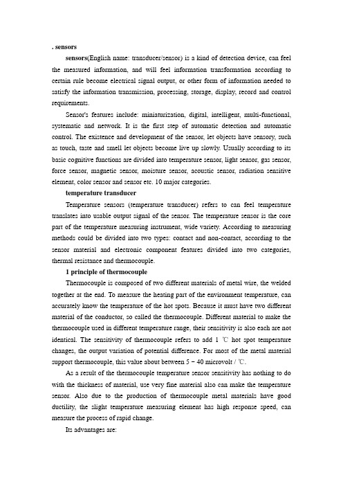
. sensorssensors(English name: transducer/sensor) is a kind of detection device, can feel the measured information, and will feel information transformation according to certain rule become electrical signal output, or other form of information needed to satisfy the information transmission, processing, storage, display, record and control requirements.Sensor's features include: miniaturization, digital, intelligent, multi-functional, systematic and network. It is the first step of automatic detection and automatic control. The existence and development of the sensor, let objects have sensory, such as touch, taste and smell let objects become live up slowly. Usually according to its basic cognitive functions are divided into temperature sensor, light sensor, gas sensor, force sensor, magnetic sensor, moisture sensor, acoustic sensor, radiation sensitive element, color sensor and sensor etc. 10 major categories.temperature transducerTemperature sensors (temperature transducer) refers to can feel temperature translates into usable output signal of the sensor. The temperature sensor is the core part of the temperature measuring instrument, wide variety. According to measuring methods could be divided into two types: contact and non-contact, according to the sensor material and electronic component features divided into two categories, thermal resistance and thermocouple.1 principle of thermocoupleThermocouple is composed of two different materials of metal wire, the welded together at the end. To measure the heating part of the environment temperature, can accurately know the temperature of the hot spots. Because it must have two different material of the conductor, so called the thermocouple. Different material to make the thermocouple used in different temperature range, their sensitivity is also each are not identical. The sensitivity of thermocouple refers to add 1 ℃hot spot temperature changes, the output variation of potential difference. For most of the metal material support thermocouple, this value about between 5 ~ 40 microvolt / ℃.As a result of the thermocouple temperature sensor sensitivity has nothing to do with the thickness of material, use very fine material also can make the temperature sensor. Also due to the production of thermocouple metal materials have good ductility, the slight temperature measuring element has high response speed, can measure the process of rapid change.Its advantages are:(1)high precision measurement. Because of thermocouple direct contact with the object being measured, not affected by intermediate medium.(2)the measurement range. Commonly used thermocouple from 1600 ℃to 50 ℃ ~ + sustainable measurement, some special thermocouple minimum measurable to - 269 ℃ (e.g., gold iron nickel chrome), the highest measurable to + 2800 ℃ (such as tungsten rhenium).(3) simple structure, easy to use. Thermocouple is usually composed of two different kinds of metal wire, but is not limited by the size and the beginning of, outside has protective casing, so very convenient to use. The thermocouple type and structure of the form.2. The thermocouple type and structure formation(1)the types of thermocoupleThe commonly used thermocouple could be divided into two types: standard thermocouple and non-standard thermocouple. Standard thermocouple refers to the national standard specifies its thermoelectric potential and the relationship between temperature, permissible error, and a unified standard score table of thermocouple, it has with matching display instrument to choose from. Rather than a standard thermocouple or on the order of magnitude less than the range to use standardized thermocouple, in general, there is no uniform standard, it is mainly used for measurement of some special occasions.Standardized thermocouple is our country from January 1, 1988, thermocouple and thermal resistance of all production according to IEC international standard, and specify the S, B, E, K, R, J, T seven standardization thermocouple type thermocouple for our country unified design.(2)to ensure that the thermocouple is reliable, steady work, the structure of thermocouple requirements are as follows:①of the two thermocouple thermal electrode welding must be strong;②two hot electrode should be well insulated between each other, in case of short circuit;③compensation wires connected to the free cod of a thermocouple to convenient and reliable;④protect casing thermal electrodes should be able to make sufficient isolation and harmful medium.3.The thermocouple cold end temperature compensationDue to the thermocouple materials are generally more expensive (especiallywhen using precious metals), and the temperature measurement points are generally more far, the distance to the instrument in order to save materials, reduce cost, usually adopt the compensating conductor) (the free end of the cold junction of the thermocouple to the steady control of indoor temperature, connected to the meter terminals. It must be pointed out that the role of the thermocouple compensation wire extension hot electrode, so that only moved to the control room of the cold junction of the thermocouple instrument on the terminal, it itself does not eliminate the cold end temperature change on the influence of temperature, cannot have the compensation effect. So, still need to take some of the other correction method to compensate of the cold end temperature especially when t0 indicates influence on measuring temperature 0 ℃.Must pay attention to when using thermocouple compensating conductor model match, cannot be wrong polarity, compensation conductor should be connected to the thermocouple temperature should not exceed 100 ℃.传感器传感器(英文名称:transducer/sensor)是一种检测装置,能感受到被测量的信息,并能将感受到的信息,按一定规律变换成为电信号或其他所需形式的信息输出,以满足信息的传输、处理、存储、显示、记录和控制等要求。
- 1、下载文档前请自行甄别文档内容的完整性,平台不提供额外的编辑、内容补充、找答案等附加服务。
- 2、"仅部分预览"的文档,不可在线预览部分如存在完整性等问题,可反馈申请退款(可完整预览的文档不适用该条件!)。
- 3、如文档侵犯您的权益,请联系客服反馈,我们会尽快为您处理(人工客服工作时间:9:00-18:30)。
Progress in Materials ScienceV olume 46, Issues 3–4, 2001, Pages 461–504The selection of sensorsJ Shieh,J.E Huber,N.A Fleck, ,M.F AshbyDepartment of Engineering, Cambridge University, Trumpington Street, Cambridge CB2 1PZ, UK Available online 14 March 2001./10.1016/S0079-6425(00)00011-6, How to Cite or Link Using DOI Permissions & ReprintsAbstractA systematic method is developed to select the most appropriate sensor for a particular application.A wide range of candidate sensors exist, and many are based on coupled electrical and mechanical phenomena, such as the piezoelectric, magnetostrictive and the pyro-electric effects. Performance charts for sensors are constructed from suppliers data for commercially available devices. The selection of an appropriate sensor is based on matching the operating characteristics of sensors to the requirements of an application. The final selection is aided by additional considerations such as cost, and impedance matching. Case studies illustrate the selection procedure.KeywordsSensors;Selection;Sensing range;Sensing resolution;Sensing frequency1. IntroductionThe Oxford English Dictionary defines a sensor as “a device which detects or measures some condition or property, and records, indicates, or otherwise responds to the information received”. Thus, sensors have the function of converting a stimulus into a measured signal. The stimulus can be mechanical, thermal, electromagnetic, acoustic, or chemical in origin (and so on), while the measured signal is typically electrical in nature, although pneumatic, hydraulic and optical signals may be employed. Sensors are an essential component in the operation of engineering devices, and are based upon a very wide range of underlying physical principles of operation.Given the large number of sensors on the market, the selection of a suitable sensor for a newapplication is a daunting task for the Design Engineer: the purpose of this article is to provide a straightforward selection procedure.The study extends that of Huber et al. [1] for the complementary problem of actuator selection. It will become apparent that a much wider choice of sensor than actuator is available: the underlying reason appears to be that power-matching is required for an efficient actuator, whereas for sensors the achievable high stability and gain of modern-day electronics obviates a need to convert efficiently the power of a stimulus into the power of an electrical signal. The classes of sensor studied here are detailed in the Appendices. 2. Sensor performance chartsIn this section, sensor performance data are presented in the form of 2D charts with performance indices of the sensor as axes. The data are based on sensing systems which are currently available on the market. Therefore, the limits shown on each chart are practical limits for readily available systems, rather than theoretical performance limits for each technology. Issues such as cost, practicality (such as impedance matching) and reliability also need to be considered when making a final selection from a list of candidate sensors.Before displaying the charts we need to introduce some definitions of sensor characteristics; these are summarised in Table 1.1 Most of these characteristics are quoted in manufacturers' data sheets. However, information on the reliability and robustness of a sensor are rarely given in a quantitative manner.Table 1. Summary of the main sensor characteristicsRange maximum minus minimum value of the measured stimulusResolution smallest measurable increment in measured stimulusSensing frequency maximum frequency of the stimulus which can be detectedAccuracy error of measurement, in% full scale deflectionSize leading dimension or mass of sensorOpt environment operating temperature and environmental conditionsReliability service life in hours or number of cycles of operationDrift long term stability (deviation of measurement over a time period)Cost purchase cost of the sensor ($ in year 2000)Full-size tableIn the following, we shall present selection charts using a sub-set of sensor characteristics: range, resolution and frequency limits. Further, we shall limit our attention to sensors which can detect displacement, acceleration, force, and temperature.2 Each performance chart maps the domain of existence of practical sensors. By adding to the chart the required characteristics for a particular application, a subset of potential sensors can be identified. The optimal sensor is obtained by making use of several charts and by considering additional tabular information such as cost. The utility of the approach is demonstrated in Section 3, by a series of case studies.2.1. Displacement sensorsConsider first the performance charts for displacement sensors, with axes of resolution δversus range R, and sensing frequency f versus range R, as shown in Fig. 1 and Fig. 2, respectively.Fig. 1. Resolution versus sensing range for displacement sensors. View thumbnail imagesFig. 2. Sensing frequency versus sensing range for displacement sensors.View thumbnail images2.1.1. Resolution —sensing range chart (Fig. 1)The performance regime of resolution δversus range R for each class of sensor is marked by a closed domain with boundaries given by heavy lines (see Fig. 1). The upper limit of operation is met when the coarsest achievable resolution equals the operating range δ=R. Sensors of largest sensing range lie towards the right of the figure, while sensors of finest resolution lie towards the bottom. It is striking that the range of displacement sensor spans 13 orders of magnitude in both range and resolution, with a large number of competing technologies available. On these logarithmic axes, lines of slope +1 link classes of sensors with the same number of distinctmeasurable positions, . Sensors close to the single position line δ=R are suitable as simple proximity (on/off) switches, or where few discrete positions are required. Proximity sensors are marked by a single thick band in Fig. 1: more detailed information on the sensing range and maximum switching frequency of proximity switches are summarised in Table 2. Sensors located towards the lower right of Fig. 1 allow for continuous displacement measurement, with high information content. Displacement sensors other than the proximity switches are able to provide a continuous output response that is proportional to the target's position within the sensing range.Fig. 1 shows that the majority of sensors have a resolving power of 103–106 positions; this corresponds to approximately 10–20 bits for sensors with a digital output.Table 2. Specification of proximity switchesProximity switch typeMaximum switching distance (m) Maximum switchingfrequency (Hz) Inductive6×10−4–1×10⁻¹ 5–5000 Capacitive1×10−3–6×10⁻² 1–200 Magnetic 3×10⁻³–8.5×10⁻² 400–5000 Pneumatic cylinder sensors (magnetic) Piston diameter 8×10⁻³–3.2×10−1300–5000 Ultrasonic1.2×10−1–5.2 1–50 Photoelectric 3×10⁻³–300 20–20,000Full-size tableIt is clear from Fig. 1 that the sensing range of displacement sensors cluster in the region 10−5–101 m. To the left of this cluster, the displacement sensors of AFM and STM, which operate on the principles of atomic forces and current tunnelling, have z-axis-sensing ranges on the order of microns or less. For sensing tasks of 10 m or above, sensors based on the non-contacting technologies of linear encoding, ultrasonics and photoelectrics become viable. Optical linear encoders adopting interferometric techniques can achieve a much higher resolution than conventional encoders; however, their sensing range is limited by the lithographed carrier (scale).A switch in technology accounts for the jump in resolution of optical linear encoders around the sensing range of 0.7 m in Fig. 1.Note that “radar ”, which is capable of locating objects at distances of several thousand kilometres,3 is not included in Fig. 1. Radar systems operate by transmitting high-frequency radio waves and utilise the echo and Doppler shift principles to determine the position and speed of the target. Generally speaking, as the required sensing range increases, sensors based on non-contact techniques become the most practicable choice due to their flexibility, fast sensing speed and small physical size in relation to the length scale detected. Fig. 1 shows that sensors based on optical techniques, such as fibre-optic, photoelectric and laser triangulation, cover the widest span in sensing range with reasonably high resolution.For displacement sensors, the sensing range is governed by factors such as technology limitation, probe (or sensing face) size and the material properties of the target. For example, the sensing distance of ultrasonic sensors is inversely proportional to the operating frequency; therefore, a maximum sensing range cut-off exists at about R=50 m. Eddy current sensors of larger sensing face are able to produce longer, wider and stronger electromagnetic fields, which increase their sensing range. Resolution is usually controlled by the speed, sensitivity and accuracy of the measuring circuits or feedback loops; noise level and thermal drift impose significant influences also. Sensors adopting more advanced materials and manufacturing processes can achieve higher resolution; for example, high-quality resistive film potentiometers have a resolution of better than 1 μm over a range of 1 m (i.e. 106 positions) whereas typical coil potentiometers achieve only 103 positions.2.1.2. Sensing frequency — sensing range chart (Fig. 2)When a displacement sensor is used to monitor an oscillating body, a consideration of sensing frequency becomes relevant. Fig. 2 displays the upper limit of sensing frequency and the sensorrange for each class of displacement sensor. It is assumed that the smallest possible sensing range of a displacement sensor equals its resolution; therefore in Fig. 2, the left-hand side boundary of each sensor class corresponds to its finest resolution.4 However, sensors close to this boundary are only suitable as simple switches, or where few discrete positions are to be measured.Lines of slope −1 in Fig. 2 link classes of sensors with the same sensing speed, fR. For contact sensors such as the LVDT and linear potentiometer, the sensing speed is limited by the inertia of moving parts. In contrast, many non-contact sensors utilise mechanical or electromagnetic waves and operate by adopting the time-of-flight approach; therefore, their maximum sensing speed is limited by the associated wave speed. For example, the maximum sensing speed of magnetostrictive sensors is limited by the speed of a strain pulse travelling in the waveguide alloy, which is about 2.8×10³ m s−1.The sensing frequency of displacement sensors is commonly dependent on the noise levels exhibited by the measuring electronic circuits. Additionally, some physical and mechanical limits can also impose constraints. For example, the dynamic response of a strain gauge is limited by the wave speed in the substrate. For sensors with moving mass (for example, linear encoder, LVDT and linear potentiometer), the effects of inertial loading must be considered in cyclic operation. For optical linear encoders the sensing frequency increases with range on the left-hand side of the performance chart, according to the following argument. The resolution becomes finer (i.e. δdecreases in an approximately linear manner) with a reduced scan speed V of the recording head. Since the sensor frequency f is proportional to the scan speed V, we deduce that f increases linearly with δ, and therefore f is linear in the minimum range of the device.2.2. Linear velocity sensorsAlthough velocity and acceleration are the first and second derivatives of displacement with respect to time, velocity and acceleration measurements are not usually achieved by time differentiation of a displacement signal due to the presence of noise in the signal. The converse does not hold: some accelerometers, especially navigation-grade servo accelerometers, have sufficiently high stability and low drift that it is possible to integrate their signals to obtain accurate velocity and displacement information.The most common types of velocity sensor of contacting type are electromagnetic, piezoelectric and cable extension-based. Electromagnetic velocity sensors use the principle of magnetic induction, with a permanent magnet and a fixed geometry coil, such that the induced (output) voltage is directly proportional to the magnet's velocity relative to the coil. Piezo-velocity transducers (PVTs) are piezoelectric accelerometers with an internal integration circuit which produces a velocity signal. Cable extension-based transducers use a multi-turn potentiometer (or an incremental/absolute encoder) and a tachometer to measure the rotary position and rotating speed of a drum that has a cable wound onto it. Since the drum radius is known, the velocity and displacement of the cable head can be determined.5Optical and microwave velocity sensors are non-contacting, and utilise the optical-grating or Doppler frequency shift principle to calculate the velocity of the moving target. Typical specifications for each class of linear velocity sensor are listed in Table 3.Table 3. Specification of linear velocity sensorsSensor class Maximum sensingrange (m/s)Resolution (number ofpositions)Maximum operatingfrequency (Hz)Magnetic induction 25–360 5×10⁴–5×10⁵ 100–1500Sensor class Maximum sensingrange (m/s)Resolution (number ofpositions)Maximum operatingfrequency (Hz)PVT 0.25–1.3 1×10⁵–5×10⁵ ∼7000Cable-extension 0.7–15 1×10⁵–1×10⁶ 1–100Optical andmicrowave13–165 ∼1×10⁵ > 10,000目录1. 简介 (8)2. 传感器性能图表 (9)2.1.位移传感器 (10)2.1.1.分辨率- 感应范围图(图1) (11)2.1.2.检测频率–检测范围图(图2) (12)2.2.线性速度传感器 (12)问题3-4,2001年第46卷,页461-504传感器的选择J Shieh,J.E Huber,N.A FleckM.F Ashby剑桥大学工程系,英国剑桥CB2的1PZ,,Trumpington街________________________________________摘要对于一个特定的应用系统来说要选择最为合适的传感器。