Quick Check 600&800系列条码检测仪使用手册2
600磅调节拖车小车产品说明书

600 LB. ADJUSTABLE TRAILER DOLLYOWNER’S MANUALWARNING:Carefully read and understand all ASSEMBLY AND OPERATIONINSTRUCTIONS before operating. Failure to follow the safety rules and other basic safety precautions may result in serious personal injury.10152015PATENT#7,845,670This product is designed for certain applications only. The manufacturer cannot be responsible for issues arising from modification. We strongly recommend that this product not be modified and/or used for any application other than that for which it was designed. If you have any questions relative to a particular application, DO NOT use the product until you have first contacted us to determine if it can, or should, be performed on the product.For technical questions, please call 218-943-6296..TECHNICAL SPECIFICATIONSGENERAL SAFETY RULESWARNING: Read and understand all instructions. Failure to follow all instructions listed below may result in serious injury.CAUTION: Do not allow persons to operate or assemble this adjustable trailer dolly until they have read this manual and have developed a thorough understanding of how the adjustable trailer dolly works.WARNING:The warnings, cautions, and instructions discussed in this instruction manual cannot cover all possible conditions or situations that could occur. It must be understood by the operator that common sense and caution are factors that cannot be built into this product, but must be supplied by the operator.SAVE THESE INSTRUCTIONSWORK AREA•Keep work area clean, free of clutter, and well-lit.Cluttered and dark work areas can cause accidents.•Keep children and bystanders away while operating an adjustable trailer dolly.•Be alert of your surroundings. Using an adjustable trailer dolly in confined work areas may put you in dangerous situations.PERSONAL SAFETY•Stay alert, watch what you are doing, and use common sense when using an adjustable trailer dolly. Do not use an adjustable trailer dolly while you are tired or under the influence of drugs, alcohol, or medication. A moment of inattention while operating an adjustable trailer dolly may result in serious personal injury.•Dress properly. Do not wear loose clothing, dangling objects, or jewelry. Keep your hair, clothing, and gloves away from moving parts. Loose clothes, jewelry, or long hair can be caught in moving parts.•Use safety apparel and equipment. Use approved safety goggles or safety glasses with side shields or, when needed, a face shield. Also use non-skid, safety shoes and gloves whenappropriate.TRAILER DOLLY USE AND CARE•Do not modify the adjustable trailer dolly in any way. Unauthorized modification may impair the function and/or safety and could affect the life of the equipment. There are specificapplications for which the adjustable trailer dolly was designed.•Always check for damaged or worn-out parts before using the adjustable trailer dolly.Broken parts will affect the adjustable trailer dolly operation. Replace or repair damaged or worn parts immediately.•Do not exceed the adjustable trailer dolly load capacity.•Distribute the load evenly. Uneven loads may cause the adjustable trailer dolly to tip, resulting in personal injury to the operator or others.•Use the adjustable trailer dolly on flat and level surfaces capable of supporting the adjustable trailer dolly and its maximum load. Pulling or pushing a load on a slanted or uneven surface can result in loss of control.•Store idle adjustable trailer dolly. When adjustable trailer dolly is not in use, store it in a secure place out of the reach of children. Inspect it for good working condition prior to storage and before re-use.ASSEMBLYSee parts diagram for reference during assembly1. Attach the Link Bracket (#2) to the T-Bar Handle (#1) using four Bolts (#3), four Flat Washers(#4), and four Lock Washers (#5). Put the washers on the bolt before screwing into the holes.2. Attach the Link Bracket (#2) to the Axle Assembly (#16) in the bottom hole using one Bolt(#18), one Washer (#9), and one Nut (#10).3. Attach the upper end of the Brace (#7) and V Support (#6) to the Link Bracket (#2) using oneBolt (#8), one Washer (#9), and one Nut (#10).4. Attach the lower end of the V Support (#6) to the Link Bracket (#2) using one Bolt (#8), oneWasher (#9), and one Nut (#10).5. Attach the lower end of the Brace (#7) to the Axle Assembly (#16) using one Bolt (#13), oneWasher (#9), and one Nut (#10).6. Install the two Flat Free Tires (#17) on both ends of the Axle Assembly (#16) using two HexNuts (#19) and two Split Pins (#20).7. Install the Coupler Ball (#11) onto the Adjustable Tube (#12). Insert the Adjustable Tube (#12)into the Axle Assembly (#16) and secure it with the Pin (#15) and the R Pin (#14).8. Check and tighten all bolts as needed.9. Adjust the Adjustable Tube to the proper height for your trailer. Make sure the pin is securedthrough the Adjustable Tube and the welded tube on the frame. Place the R Pin into the hole of the Pin to secure the Pin.OPERATION1. The designed load limit is 600 lbs. for the adjustable trailer dolly alone, not including loadsupported by trailer wheels. Do not exceed the rated capacity.2. Always keep arms, feet, legs, etc. out from under the trailer tongue while hitching, unhitching,or moving the trailer. Children should always be kept at a safe distance.3. Always make sure any loaded trailer is blocked properly while the adjustable trailer dolly isbeing moved into place.4. Make sure the trailer tongue is securely connected to the adjustable trailer dolly coupler ballbefore attempting to unblock and move the trailer.5. Take precautions to prevent uncontrolled movement of the trailer once it is connected to theadjustable trailer dolly. Remember, the slope of a roadbed surface is difficult to judge, and the pull of gravity can result in a dangerously out-of-control trailer.6. If the adjustable trailer dolly is being connected to a trailer that is being stored over a lengthyperiod of time, make sure both the trailer and the adjustable trailer dolly are blocked properly.7. Keep the adjustable trailer dolly clean and free of road dirt. Inspect the adjustable trailer dollybefore each use to make sure all parts are securely in place and are in working order.Periodically lubricate moving parts.WARNING: FAILURE TO FOLLOW THESE INSTRUCTIONS COULD RESULT IN LOSS OF LOAD, PERSONAL INJURY, AND/OR DAMAGE TO PROPERTY.DIAGRAM & PARTS LIST.For replacement parts and/or technical questions, please call 218-943-6296. WARRANTY: One-year limited parts warranty.Distributed by:TG PO Box 203 Miltona, MN 56354。
Amprobe UAT-600地下设施定位器系列用户说明书

Accidentally hitting a utility line during a project can lead to costly repairs and create hazardous public safety situations. Digging in the wrong place can also lead to unnecessary delays and costs for your project, and ultimately, your company. Avoid this disruption with the rugged and durable Amprobe UAT-600 Series, designed to accurately pinpoint underground utilities and buried services up to 20 feet deep.Designed for electricians with a CAT IV 600 V rating, the locating kits come complete and ready for use with a Transmitter, Receiver, test lead kit, batteries and additional fuses, all in a mobile, protective duffle bag.The UAT-620 kit also includes a Signal Clamp for transmitting a signal when it is not possible to make electrical contact with the cable to be traced. For applications where ground fault locating is required, use the UAT-600 Transmitter in combination with the optional A-Frame accessory.Intuitive Transmitter automatically chooses the correct locatingfunctionSC-600 Signal Clamp included in the UAT -620 KitLarge LCD Display with auto backlight for clear viewing in full sunlightLocateunderground utilities up to 20 ft.UAT -600 SeriesUnderground Utilities LocatorAccurately and safely pinpoint underground utilities before you digUAT -620Underground Utilities Locator KitAF-600 A-Frame Accessory*Ground Fault FinderSee page 2 for specifications* (Not included in the UAT-610 and UAT-620 Kits)Safety CertificationAll Amprobe tools, including the Amprobe UAT-600 Series, are rigorously tested for safety, accuracy, reliability, and ruggedness in our state-of-the-art test lab. In addition, Amprobe products that measure electricity are listed by a 3rd party safety lab, either UL or CSA. This system assures that Amprobe products meet or exceed safety regulations and will perform in a tough, professional environment formany years to come.Features and Highlights• Multiple tracing modes allow you to locate and trace energized and de-energized utilities in a variety of applications• The intuitive Transmitterautomatically chooses the correctlocating function based on the connectedaccessory and includes selectable 8/33kHz frequencies• The Receiver’s high-contrast display allows for clear viewing in full sunlight and features an automatic backlight for shaded and dark areas• Rated CAT IV 600 V , ensuring safety when working with energized cables • Semi-automatic gain control quickly detects tracing signal and allows precise adjustment of the receiver sensitivity• Accurate depth measurement to 20 ft• Rugged, durable construction: water and dust resistant to IP54 and drop proof to 3.28 ft (1 m)• Use the Signal Clamp to induce asignal without making electrical contact (UAT -620)• Ground fault locating with the optional A-Frame accessory • Comes as a complete kit, ready for useLCD Display with autobacklightDetect ground faults on cables and pipesAF-600-A-FrameGround Fault FinderAF-600 A-FrameGround Fault FinderSave time and money by pinpointing leakage pointsGround faults are a common problem with electrical cables. Find any fault with the AF-600 A-Frame cable ground fault finder, specifically designed for use with the Amprobe UAT -600 Series.Set up the UAT -600-T Transmitter to apply a fault find signal to the utility under test, the AF-600 A-Frame receives the signal and locates the place of the fault. The AF-600 will pinpoint where a cable metal conductor (either a sheath or a metallic conductor of the wire) touches the ground and can also detect other conductors to ground faults such as pipeline coating defects.Carrying Case, User ManualThe AF-600 comes complete with batteries and a carrying caseFeatures and Highlights • Identify any point of leakage around a cable • Locate cable and wire ground faults, sheath faults or pipeline coating defects, where the utility is in direct contact with the ground • Find the exact point where metal is touching the ground and power is leaking, ie, a shield is rusted or a rubber buffer is broken, creating noise on a cable • Advanced technology and digital signal processing makes pinpointing process fast, accurate and clear:-Compass guidance with numeric fault field strength indicates the direction of the fault -Distance sensitive left and right arrows guides the user to precisely follow the path of the buried utility-Automatic gain control quickly detects tracing signal and precisely adjusts the A-Frame sensitivity-Adjustable volume controlsClearly view the LCD display in bright sunlightPinpoint fault location by using the AF-600 with the UAT-600 TransmitterSC-600Signal ClampTL-UAT -600Test Leads KitSC-600 Signal Clamp(included in the UAT -620 Kit only)The Signal Clamp accessory provides an efficient and safe method of applying a locate signal to a cable, enabling the Transmitter to induce a signal through the insulation into the wires or pipes. The clamp works on low impedance closed circuits only.Test Leads Kit(included in the UAT -610 and UAT -620 Kits)TL-UAT -600 Test Leads Kit includes: Black test lead with detachable black alligator clip, Red test lead with permanently attached red alligator clip, Ground stakeTrace an individual utility by connecting the The Transmitter will automatically change modes The Receiver’s high contrast LED screen is easy toUAT-620 Underground Utilities Locator Kit。
Leviton ATLAS-X1 Cat 6A Component-Rated UTP QUICKP

Page 1 of 2APPLICATIONThe ATLAS-X1 Cat 6A Component-Rated UTP QUICKPORT Jack supports 10GBASE-T networks. The jack is part of a complete ATLAS-X1 Cat 6A UTP system, ideal for the most demanding mission-critical network applications. The connector supports emerging technologies and will easily adapt to network trends.SPECIFICATIONThe jack shall meet or exceed the requirements for channel and component-level electrical transmission performance as described in ANSI/TIA-568.2-D (Cat 6A), ISO/IEC11801-1 (Class E A ), and EN 50173-1 (Class E A ). The jack shall be compliant with ANSI/TIA-1096-A, c(UL)us Listed, and be independently verified for electrical transmission performance and power delivery. The jack body shall be made of die-cast zinc and all plastic components shall be made of high-impact, fire-retardant plastic rated UL 94V-0. The jack shall support tool-free termination and re-termination and shall not require a specialized termination tool. The jack wiring shall be universal to accommodate T568A and T568B wiring schemes. The jack shall be available in 13 colors; more than established by the ANSI/TIA-606-C standard. The jack shall be offered in standard and shuttered styles and select jacks shall be supplied with interchangeable icons. The jack shall be compliant with IEEE 802.3 PoE Type 1, 2, 3, 4 (100 watts max).DESIGN CONSIDERATIONS• Use in any QUICKPORT™ housing to support Cat 6A UTP connectivity in surface-mount, flush-mount, or modular furniture outlets and field-configurable panels• Can be used in conjunction with other QUICKPORT snap-in modules for voice/data/video applications over UTP , coax, and fiber• To identify ports, use different colored modules andicons for each application (full selection of ANSI/TIA-606 compatible colors, 13 available)• Robust housing and shutter protects the jack in harsh environmentsATLAS-X1™ Cat 6A Component-Rated UTP QUICKPORT™ Jack6AUJK-xx6, ICONS-ICxFEATURES• Independently tested and guaranteed to exceed all component, permanent link, and channel margins• Patented Retention Force Technology™ (RFT) protects against tine damage and increases system longevity • For Power over Ethernet, RFT maintains contact force between plug and jack, preventing arcing from intermittent disconnects• Unique design supports tool-free termination andre-termination and requires no specialized termination tool • Short jack design supports a wider range of applications (e.g. shallow boxes, enclosures, bend radius, etc.)• Terminates from 26 to 22 AWG solid or stranded conductors for use on various cable types• Robust IDCs can withstand 20 re-termination cycles and jack contacts are tested for 750 plug-mating cycles to ensure system longevity• Available in 13 ANSI/TIA-606-C compatible colors • Tested and approved for use in air-handling spaces (plenum rating) in accordance with UL Standard 2043• Select jacks available with interchangeable icons (voice, data, A/V, blank) for easy ID• Jack with internal shutter protects against dust and debris • Solid metal body dissipates 53% more heat than plastic, minimizing damage from excess heat in PoE applications • Tine geometry prevents arcing damage where plug and jack make contactSTANDARDS & REGULATIONS• ANSI/TIA-568.2-D (Cat 6A)• ISO/IEC 11801-1 (Cat 6A)• EN 50173-1 (Cat 6A)• ANSI/TIA-1096-A (formerly FCC Part 68)• IEC 60603-7 (includes IEC 60512-5-2)• IEC 60512-99-002• IEEE 802.3 PoE Type 1, 2, 3, 4 (100 watts max)• Cisco UPOE, UPOE+ (90 watts max)• Power over HDBaseT™ PoH (95 watts max)• c(UL)us Listed (UL 1863)• UL 2043 Plenum Certified • RoHS 3• ETL verified to meet the IEC 60512-99-002 standard for support of IEEE 802.3 Type 4 PoE (100 watt) applicationsCOUNTRY OF ORIGINUSA and Mexico (Contact Customer Service for details)6AUJK-xx6, ICONS-ICxUSANetwork Solutions Headquarters +1 (800) 722 2082 *******************Leviton Berk-Tek Cable : +1 (800) 237 5835 ************************Asia Pacific+852 3620 2602********************Canada+1 (800) 461 2002**********************Europe+44 (0) 1592 772124 **********************Latin AmericaMX: +52 (55) 2128 6286 LATAM: +52 (55) 2333 5963 *********************Middle East & Africa +971 (4) 247 9800 *******************NETWORK SOLUTIONS PRODUCTS ARE AVAILABLE WORLDWIDE IN OVER 100 COUNTRIES. VISIT US ONLINE AT /NS TO LEARN MORE.Page 2 of 2For further support information, visit /ns/support6AUJK-xx6, ICONS-ICx6AUJK-xx6, ICONS-ICxMECHANICAL SPECIFICATIONSDimensions:See belowMaterials: Jack Body: Die-cast zincSpring-Wire Contacts: High quality, copper-based alloy, plated with 50 microinches of gold for lowest contact resistance andmaximum life Temp. (Storage):Temp. (Installation): Temp. (Operating):Humidity (Max.):WARRANTY INFORMATIONFor Leviton product warranties, go to /ns/warrantyPART NUMBERDescriptionStandard Jack Jack with Shutter GREENPACK™12-Pack Standard Jack ATLAS-X1™ Cat 6A Component-Rated UTP QUICKPORT™ Jack, white 6AUJK-RW66AUJK-SW66AUJK-CW6ATLAS-X1 Cat 6A Component-Rated UTP QUICKPORT Jack, light almond 6AUJK-RT66AUJK-ST6—ATLAS-X1 Cat 6A Component-Rated UTP QUICKPORT Jack, ivory 6AUJK-RI66AUJK-SI6—ATLAS-X1 Cat 6A Component-Rated UTP QUICKPORT Jack, yellow 6AUJK-RY66AUJK-SY6—ATLAS-X1 Cat 6A Component-Rated UTP QUICKPORT Jack, orange 6AUJK-RO66AUJK-SO6—ATLAS-X1 Cat 6A Component-Rated UTP QUICKPORT Jack, crimson 6AUJK-RC66AUJK-SC6—ATLAS-X1 Cat 6A Component-Rated UTP QUICKPORT Jack, dark red 6AUJK-RR66AUJK-SR6—ATLAS-X1 Cat 6A Component-Rated UTP QUICKPORT Jack, purple 6AUJK-RP66AUJK-SP6—ATLAS-X1 Cat 6A Component-Rated UTP QUICKPORT Jack, blue 6AUJK-RL66AUJK-SL66AUJK-CL6ATLAS-X1 Cat 6A Component-Rated UTP QUICKPORT Jack, green 6AUJK-RV66AUJK-SV6—ATLAS-X1 Cat 6A Component-Rated UTP QUICKPORT Jack, gray 6AUJK-RG66AUJK-SG6—ATLAS-X1 Cat 6A Component-Rated UTP QUICKPORT Jack, black6AUJK-RE66AUJK-SE66AUJK-CE6ATLAS-X1 Cat 6A Component-Rated UTP QUICKPORT Jack, brown6AUJK-RB66AUJK-SB6—Green (V)Blue (L)Purple (P)Crimson (C)Dark Red (R)Orange (O)Yellow (Y)Black (E)Gray (G)Ivory (I)Light Almond (T)Brown (B)Color-matched icons (ICONS-ICx) can be ordered separately in 72-quantity packs.x = icon color。
Polycom CX600 Lync Edition手机快速用户指南说明书
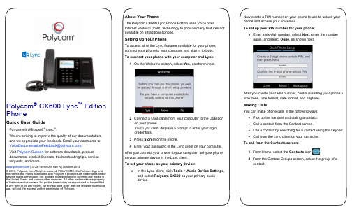
Polycom® CX600 Lync™ EditionPhoneQuick User GuideFor use with Microsoft® Lync™.We are striving to improve the quality of our documentation,and we appreciate your feedback. Email your comments to**************************************.Visit Polycom Support for software downloads, productdocuments, product licenses, troubleshooting tips, servicerequests, and more. | 3725-15999-001 Rev A | October 2013© 2013, Polycom, Inc. All rights reserved. POLYCOM®, the Polycom logo andthe names and marks associated with Polycom's products are trademarks and/orservice marks of Polycom, Inc. and are registered and/or common law marks inthe United States and various other countries. All other trademarks are propertyof their respective owners. No portion hereof may be reproduced or transmittedin any form or by any means, for any purpose other than the recipient's personaluse, without the express written permission of Polycom.About Your PhoneThe Polycom CX600 Lync Phone Edition uses Voice overInternet Protocol (VoIP) technology to provide many features notavailable on a traditional phone.Setting Up Your PhoneTo access all of the Lync features available for your phone,connect your phone to your computer and sign in to Lync.To connect your phone with your computer and Lync:1On the Welcome screen, select Yes, as shown next.2Connect a USB cable from your computer to the USB porton your phone.Your Lync client displays a prompt to enter your logincredentials.3Press Sign in on the phone.4Enter your password in the Lync client on your computer.After you connect your phone to your computer, set your phoneas your primary device in the Lync client.To set your phone as your primary device:» In the Lync client, click Tools > Audio Device Settings,and select Polycom CX600 as your primary audiodevice.Now create a PIN number on your phone to use to unlock yourphone and access your voicemail.To set up your PIN number for your phone:» Enter a six-digit number, select Next, enter the numberagain, and select Done, as shown next.After you create your PIN number, continue setting your phone’stime zone, time format, date format, and ringtone.Making CallsYou can make phone calls in the following ways:∙Pick up the handset and dialing a contact.∙Call a contact from the Contact screen.∙Call a contact by searching for a contact using the keypad.∙Call from the Lync client on your computer.To call from the Contacts screen:1From Home, select the Contacts icon .2From the Contact Groups screen, select the group of acontact.3Select a contact, and select Call, as shown next.To call by searching for a contact:1Enter your contact’s name or phone extension using thephone’s keypad.To enter a contact’s name, p ress the numbers on the keypad that correspond to the letters in your contact’s name.For example, press 8669*76484 to enter the name TonySmith and use the star key (*) for the space between thefirst and last name.2When you find your contact, select Call.To call from Microsoft Lync:1Open the Lync client on your computer, select a contact orsearch for a contact by name.2Click Call next to your contact’s name, as shown next.The call displays on your phone and in the Lync client.Answering and Holding CallsYou can answer incoming calls by picking up the handset orselecting Answer on the Incoming Call screen, as shown below.You can also choose to send an incoming call to voicemail byselecting To Voice Mail.After you answer an incoming call, the call is active. You canplace multiple active calls on hold in the In Call screen.To place an active call on hold:» Select Hold, as shown next.To switch between active and held calls:» Press , select Active Call, select a held call, andselect Resume.You can also make new calls during an active call.To make a new call during an active call:1From the In Call screen, select Menu > New Call. Theactive call is placed on hold.2Enter a phone number or select a contact and select Call.Managing Conference CallsYou can add multiple participants to an active call to initiate aconference call.To initiate a conference call:1During an active call, select Menu > Add Others, asshown next. The active call is placed on hold.2Enter a phone number or select a contact and select Add.During a conference call, you can mute your audio or mute theaudio from the call participants, or audience.To mute your audio during a call:» Press . Your audio is muted and the call participantscannot hear you.To mute the audience during a conference call: »Select Menu > Mute Audience, as shown next.You can no longer hear the audio from the other callparticipants.You can also remove a participant from a conference call at any time.To remove a participant from a conference call: 1Select a participant.2Press Menu > Remove, as shown next.The participant is removed from the conference call. Checking VoicemailIf you have new voicemail, the number of messages displaysbelow the voicemail icon on the Home screen, as shown next.To check your voicemail:1On the Home page, select , or press and hold 1 on thekeypad.The voicemail screen displays with a list of contacts whohave left messages.2Select a contact and select Play.The contact’s voicemail message plays.Transferring CallsYou can transfer active calls directly to a contact, to your mobilephone, or to a parking lot on the Lync server. The following arethree methods for transferring calls:∙Transfer Directly To Transfer the call directly to acontact without speaking to the contact first.∙Consult then Transfer To Speak with a contact beforetransferring the call.∙Transfer to Mobile Phone Transfer the call to yourmobile phone.To transfer a call:1In the In Call screen, select Menu, and select a transfermethod. For example, select Transfer Directly To, asshown next.2Depending on your transfer method, do the following:For Transfer Directly To, enter a phone number orselect a contact, and select Call.For Consult then Transfer To, enter a phone numberor select a contact, select Call, and select CompleteTransfer after you speak with the contact.For Transfer to Mobile Phone, answer the transferredcall on your mobile phone. You need to have yourmobile number saved on your phone to use this option.You can also transfer calls to a parking lot that places the call onhold on the Lync server. Calls transferred to the parking lot aregiven a retrieval number that any contact can use to retrieve thecall from the parking lot.Transferring calls to the parking lot enables you to remove thecall from your line so you can make additional calls or resume aheld call.To transfer a call to a Parking Lot:1From the In Call screen, select Menu > Transfer toParking Lot.The call is placed in the parking lot and the In Call screendisplays, as shown next.2 Provide a contact with the retrieval number for the parked call. For example, if Sarah needs to retrieve the parkedcall, instant message Sarah with the 344 retrieval number for the call.Joining Meetings from the CalendarYou can view your Microsoft ® Outlook® calendar andappointments on your phone and directly join meetings from appointments listed on your calendar. To join a meeting from your calendar: 1 From Home, select the Calendar icon.2 From Today’s Calendar , select a meeting and select Join , as shown next.Your phone dials into the meeting.Changing Your Presence Status Your presence status automatically changes based on your calendar events or phone activity. For example, if you are in a meeting or a call, your presence status displays as Busy on your phone and your Lync client. However, you can change your presence status manually at any time.To change your presence status on your phone: 1 From Home, select Menu > My Status .2 On the My Status screen, select a presence status, as shown next. The check mark indicates your current status.Your new presence status displays on your phone and Lync client.Viewing Contact CardsA contact card provides a contact’s availability , presence, phone number, schedule information, the most recent call, or apersonal note, if available. Note that contacts display in a contact group.To view a contact card:1 From Home, select the Contacts icon.2 From the Contact Groups scre en, select a contact’s group .3 Select a contact.The Contact Card screen displays, as shown next.Viewing Call LogsYou can view a history of incoming, outgoing, and missed calls on Call Logs screen. To view call logs:1 From Home, select the Call Logs icon.2 From the All Calls screen, select Menu and select the call log you want to view. For example, select View Missed Calls , as shown next.The chosen call list displays.。
AK-UCU600系列产品说明书

EXPLODED VIEWS & REPLACEMENT PARTS LIST Model No. :AK-UCU600/S/P/PS/E/ES/MC/MSNote:1.*Be sure to make your orders of replacement parts according to this list.2.Unless otherwise specified, all resistors are in OHMS, K=1,000 OHMS,all capacitors are in MICROFARADS (µF) P=µµF.3.The P.C.Board unit marked with “■” shown below the main assembled parts.4.The parts marked with E on the exploded view show the electric parts.5.INPORTANT SAFETY NOTICEComponents identified with the mark!have the special characteristics for safety When replacing anyof these components, use only the same type.6.The marking (RTL) indicates the retention time is limited for this item.After the discontinuation of this assembly in production, it will no longer be available.7.“M”in Remark column indicates needed in the periodical maintenance.10810810810810110110110110110120E6E5E4E8157Refer Page SPL-31210110110110113E7101E23972040108108101SPL-1MAIN FRAME ASSEMBLY1When replacing any of these components, use only the same type.1014746434444117116115115E7-12049105106108106107107107107101E12281071062221312752526293023E13101E1110124E1027FRONT PANEL PARTS ASSEMBLYWhen replacing any of these components, use only the same type.10110110111110110110310110110510111010341(Accessory)104104104111111112105105232E11136564E35511559343310383710335148818E910534MAIN FRAME ASSEMBLY2When replacing any of these components, use only the same type.SPL-341(Accessory)4242481111EDS1208U EDGE SADDLE121PS1UCU600Z AC INLET UNIT13VGH5425REAR JACK SHEET14VJF1007EDGE GUARD SMALL15VJF1518CABLE CLIP75VJF1518CABLE CLIP26VJF1533EDGE GUARD17VJF1562LOCKING CLAMP28VKA0117PLASTIC FOOT49VML3932AC CORD HOOK110VMP0E60OPT CN PLATE(LEMO)110VMP0E61OPT CN PLATE(TAJIMI)111VMP0L10CENTER FRAME112DVMD1080Z MAIN PB PLATE113VMP0L12INTERFACE PB BRACKET114VMP0L14CHASSIS115VMZ3976INSULATOR2116VMZ3978INSULATOR31 17VSC6577OPT SHIELD BRACKET118VSC6554CABLE GUIDE119VSC6559POWER SHIELD BRACKET120VSC6560POWER_TOP_SHIELD121VEE1R71CABLE121VEE1R74CABLE122VEK0V88POWER SW UNIT123VGH5329SD CARD NAME PLATE124VGQ1J24SD CARD HOLDER125VGU0S06KNOB126VEE1R91CABLE127VGU0S07BUTTON528VMP0E57SD CARD PB HOLDER129VMP0L09FRONT FRAME1301YP1UCU600Z FRONT PANEL 1UNIT131VGM2614XLR SPACER132L6FAYYYD0025FAN MOTOR133L6FAYYYH0353FAN MOTOR1 348H2A013AB NUT235DVGT1116Z REAR PANEL136J0KG00000201FERRITE CORE137VEE1S17CABLE138VEE1S18CABLE139K7ACBY000005OPT MODULE1 40VGM2553TOP COVER141VFC5190RACK ADAPTOR UNIT2Accessory 42VEE1S07OPT. CONNECTOR W/CABLE (LEMO)142VEE1S13OPT. CONNECTOR W/CABLE (TAJIMI)143DVMY1039Z HEAT SINK144DVUF1089Z SPACER445DVWD1058Z MAIN-USC(POWER) WIRE UNIT146L6FAHBAH0010FAN MOTOR147L6GZYYYG0001FAN MOTOR148VJF0723CLAMPER149DVMH1180Z SDI PLATE1100XYM4+E8V SCREW3101XYN3+J8FJ SCREW68102XYN26+J6FN SCREW11103XYN3+J10FJK SCREW28104VMS8337SCREW6105XSN26+6FN SCREW17106XTB3+8GFJK SCREW6107XYN3+J6FJK SCREW16108XSB3+6FN SCREW24109XSB4+10FJK SCREW12110XSB4+30FN SCREW2111XSN3+8FN SCREW14112XTB3+6GFJ SCREW2113XYN3+J14FJK SCREW2115XYN3+A5FJ SCREW2116XYN3+A6FJK SCREW2117XYN3+J28FJ SCREW2VEE1R87CABLE1CN1004(MAIN PCB)-CN100(BNC P.C.B)VEE1R92CABLE1CN9100(MIC PCB)-CN1004(INTERFACE PCB)VEE1R93CABLE1CN12(POWER SUB PCB)-CN9400(MAIN PCB),-CN2000)VEE1R94CABLE1CN11(POWER SUB)-CN102(POWER PCB)VEE1R95CABLE1CN107(POWER PCB)-CN1006(MAIN PCB)VEE1R98CABLE1CN1(FAN CN PCB)-CN1007(MAIN PCB)VEE1R99CABLE1CN1005(MAIN PCB)-CN102(BNC PCB)VEE1R88CABLE1CN950(POWER LED)-CN601(FRONT LED)VEE1R90CABLE1CN303(FRONT SW PCB)-CN1009(INTERFACE PCB)VEE1S64CABLE1CN1101(MAIN PCB)-CN1(FAN CN2 PCB)VWJ10J6055L0FLEXIBLE CABLE1CN1003 (MAIN PCB)-CN101(BNC PCB)VWJ20J6080L0FLEXIBLE CABLE1CN301(FRONT SW PCB)-CN600(FRONT LED PCB)VWJ40J6090L0FLEXIBLE CABLE1CN900(SD CARD PCB)-CN1002(MAIN PCB)VJF1084CABLE BINDER1VJF1587CABLE CLIP1VJF1558PAN TIES PLT1M2VMT2385GASKET2VMT2432GASKET1VMT2529GASKET1VMT2176COOLING SHEET B1VMT1821GASKET1VMT2434GASKET1VMF0585HIMERON TAPE2VGQ0C12COOLING SHEET 411CL001195AAA COATING CLIP2Refer to disassembly procedure DIS-3 and DIS-16K2CG3YY00169AC PLUG WITH CABLE 1FOR AK-UCU600/S/P/PS K2CN3YY00021AC PLUG WITH CABLE FOR AK-UCU600E/ES K2CT3YY00072AC PLUG WITH CABLE FOR AK-UCU600E/ESK2CK3YY00081AC PLUG WITH CABLE FOR AK-UCU600MC/MS VPK5460ACCESSORY BOX 1DVPG1207001Z PACKING CASE IN 1FOR AK-UCU600/S/P/PS/E/ES DVPG1208001Z PACKING CASE OUT 1FOR AK-UCU600/S/P/PS/E/ES VPG3K24PACKING CASE IN 1FOR AK-UCU600MC/MS DVPG1209001Z PACKING CASE OUT 1FOR AK-UCU600MC/MSVPN7852CUSHION2Part No.Part Name & DescriptionPcsRemark■ E1VEP60A05AFAN CN 3 P.C.BOARD 1 ■ E21PB1DVLB1271Z USC P.C.BOARD 1 ■ E3VEP60983A FAN CN P.C.BOARD 1 ■ E4VEP61375B CCU POWER P.C.BOARD 1 ■ E5VEP61376B CCU POWER CTL P.C.BOARD 1 ■ E6VEP61377APOWER SUB P.C.BOARD 1 ■ E71PB1DVLB1270Z MAIN P.C.BOARD 1 ■ E8VEP64196D IF.P.C.BOARD 1 ■ E9VEP64198B MIC P.C.BOARD1 ■ E10VEP60976A FRONT SW P.C.BOARD 1 ■ E11VEP60977A FRONT LED P.C.BOARD 1 ■ E12VEP60978A SD CARD P.C.BOARD 1 ■ E13VEP60979APOWER LED P.C.BOARD1■ E21PB1DVLB1271Z USC P.C.BOARD JK100K1QYY2YB0014BNC CONNECTOR 1JK101K1QYY1YB0090BNC CONNECTOR 1JK102,03K1QYY2YB0014BNC CONNECTOR 2JK104K1QYY3YB0004BNC CONNECTOR1Ref. No.ELECTRICAL REPLACEMENT PARTS LISTPart No.Part Name & DescriptionPcs Remark■ E4VEP61375B CCU POWER P.C.BOARD C104ECQU2A474ML P.CAPACITOR CH100V 0.47U 1 C105,06F1BAH1020001 C.CAPACITOR CH 1000P 2 C108ECQU2A474ML P.CAPACITOR CH100V 0.47U 1 C114,16F0CZZ105A121 F.CAPACITOR CH 1U 2 C119ECQU2A474ML P.CAPACITOR CH100V 0.47U 1 C120F0CZZ105A121 F.CAPACITOR CH 1U 1 C141ECQU2A225MLA P.CAPACITOR CH100V 2.2U 1 C154ECQE6473KF P.CAPACITOR CH 0.047U 1 C155F1BAH2210001 C.CAPACITOR CH 220P 1 C179ECQU2A474ML P.CAPACITOR CH100V 0.47U 1C208,09F1BAH2220002 C.CAPACITOR CH 220P 2 F101K5E103BZA004FUSE 1 F102,03K5H312YA0121FUSE 2 IC121C0ZBZ0002369IC 1 IC123C0ZBZ0002369IC 1 IC126C0ZBZ0002369IC 1 IC502,04C0ZBZ0002369IC 2IC505B3PBA0000837IC1 LF101-04G0B652K00001COIL 6500UH 4 LF115G0B652K00001COIL 6500UH 1 PC101-09B3PBA0000836PHOTO COUPLER 9 PC115B3PBA0000836PHOTO COUPLER1 R106D0BF155JA044M.RESISTOR 1/2W 1500K 1 T102G4DYA0000790TRANSFORMER 1 T103G4DYA0000789TRANSFORMER1■ E6VEP61377A POWER SUB P.C.BOARD C13,14F1BAH1020001 C.CAPACITOR CH 1000P 2 C15ECQU2A474ML P.CAPACITOR CH100V 0.47U 1 C19F0CZZ105A121 F.CAPACITOR CH 1U 1 C45ECQE6473KF P.CAPACITOR CH 0.047U 1C46F1BAH3920010 C.CAPACITOR CH 3900P 1 F11K5G312YA0159FUSE1 PC11,12B3PBA0000836PHOTO COUPLER2 R12D0BF155JA044M.RESISTOR 1/2W 1500K 1 T12G4DYA0000576TRANSFORMER1Ref. No.ELECTRICAL REPLACEMENT PARTS LISTRef. No.Part No.Part Name & Description Pcs Remark ■ E71PB1DVLB1270Z MAIN P.C.BOARDCN9400K1KA02A00735CONNECTORJK1001K1QYY2YB0014BNC CONNECTOR1JK1002K1QYY3YB0004BNC CONNECTOR1JK1003,04K1QBB2YB0001BNC CONNECTOR2JK1005,06K1QYY2YB0014BNC CONNECTOR2JK1900K2LC1YYB0028LAN TRUNK CONNECTOR1PA1002K5H1021A0004FUSE1PA9400K5H2012A0007FUSE2E7-1VMT2169COOLING SHEET A2■ E8VEP64196D IF.P.C.BOARDCN1005 K1FB109BA018TRUNKCONNECTOR1CN1006K1FY115BA010AUX CONNECTOR1CN1007K1FB125B0101COMMUNICATION CONNECTOR1JK1100K2LC1YYB0028LAN CONNETOR1■ E9VEP64198B MIC P.C.BOARDJK9100,01K1AA103A0007CONNECTOR2■ E10VEP60976A FRONT SW P.C.BOARDSW300 K0E112A00133SWITCH1SW303K0E112A00145SWITCH1SW306K0E112B00111SWITCH1SW307K9AA015Y0049SWITCH1SW308K0E112A00145SWITCH1SW309 K0E112A00133SWITCH1VR300,01D2BCA14B0010VARIABLE RESISTOR2■ VEK0V87AC INLET UNITC1F1BAH1020001 C.CAPACITOR CH 1000P1C2ECQU2A474ML P.CAPACITOR CH100V 0.47U1C3F1BAH1020001 C.CAPACITOR CH 1000P1F1K5E103BZA004FUSE1LF1,F2G0B102M00009COIL 1000UH2R1,R2D0BF155JA044M.RESISTOR 1/2W 1500K2。
洗衣机Quick Reference Guide

water.
Adding rinse aid
1. Press the catch on the lid
of the dispenser for rinse
2
aid and lift .
gether and lift
1
the coarse filter
out .
Cleaning spray arms
1. Unscrew the upper spray arm and
2
pull down to remove .
1
2
5. Clean the filter elements under running water.
1) 0:15 - 0:15 2) 0,050 - 0,050 3) 4,0 - 4,0
1 Suitable programme for running at night: it takes longer, but is extremely quiet.
1
3. Close the lid of the dispenser for rinse aid. a The lid clicks into position.
Tip: Connect your appliance to a mobile device. You can conveniently change all settings using the Home Connect app. 1. Install the Home Connect app on your mo-
QuickScan使用说明说明书
10 11 Place in the QuickScan carrier and slide carrier in.
Results Screen will appear when scanning is
minutes. Cut off and
Click “Read Test” on Main
complete. Enter sample
discard bottom pad with
Menu and choose matrix
identification data and
arrow tape and read
group “MG2.” Aflatoxin
use buttons to save or
promptly.
results are reported up
4 Shake for 1 minute on mechanical shaker (or vigorously by hand for 2 minutes)
5 Centrifuge a portion of extract for 30 seconds at 2000 x g (NOT RPM).
Ensure Incubator has reached 22°C
*Note: acclimation is only required when the ambient temperature is unknown or outside of 20-24°C (68-75°F)
3 Add 100 mL of 50% ethanol and cap tightly
print report.
to 30 ppb. (Dilution steps
HPP条码检测仪中文使用说明书(QUICK CHECK 850)-原创
HPP条码检测仪中文使用说明书(QUICK CHECK 850)第一章略第二章2-1快速启动说明如果你对条码检测仪比较熟悉,本章会在几分钟内让你灵活运用。
我们假设工厂默认值是有效的。
1.安装电池(第一章)●打开设备底部的电池盖。
●将四个电池装进间隔内,电池的正极要跟盒上的+号对应起来。
●将电池盖该上。
2.充电(第一章)●将交流充电器插到设备后面的插孔里。
●将充电器插在壁装交流电源插座上。
●给已完全放电的电池充电至少要12个小时,低电量的电池充电时间会少一些。
●充完电后,将充电器从设备上拔掉。
3.打开检测仪(第一章)●按POWER键,设备发出四次快速的嘟嘟响。
如果设备显示:* RECALIBRATE,校准设备,进入步骤4。
* LOW BATTERY!,充电,进入步骤2。
* NO PRINTER A TTACHED…记录被存储在缓冲器。
用箭头键选择一项。
用当前的自动打印/存储设置继续扫描,清除记录或更改自动打印/存储设置Off(不存储数据)。
进入步骤5。
(第五章)* PRINT BUFFER…记录被存储在缓冲器。
用箭头键选择一项。
继续扫描让记录存在缓冲器里,打印记录或清除记录。
进入步骤5。
* SCAN,进入步骤5。
* QUICK-CHECK打开菜单,进入步骤5。
4.校准设备(第一章)●扫描反射片(在设备底部),或者本手册后面的反射页,如果你使用鼠标式条码读入器。
正确扫描后会有三声嘟嘟叫(一长2短)。
●继续扫描十次反射片。
2-25.扫描条码符号(第三章)●出现扫描等级显示。
(扩大准确度设置默认值为关)●继续扫描条码9次来获得最终的条码等级(#Scan/Symbol设置默认值为10)。
6.回顾扫描结果(第四章)●出现标准译码显示。
●用箭头键显示数据或扫描SSTR代码显示数据。
7.打印扫描结果(第三章)●如果检测仪连接到开着的打印机上,结果就会自动打印出来(自动打印/存储设置默认值为开)。
●如果打印机没有连接上或是关的,结果就会被存储在缓冲器里。
IE(工业工程)标准工时
13
HI-13
Insert L901.L301.F1.D901
2 31.87 28.56 27.39 26.88 29.55 31.87 26.88 14.43
14
HI-14
Insert SK.CR1.CX1.CX2
2 31.67 30.59 31.64 29.68 30.14 31.67 29.68 15.37
26
T U-04
Total inspection
1 15.99 15.34 14.28 13.48 10.38 15.99 10.38 13.89
27
ICT
Testing components of main board
1 10.23 12.34 11.25 13.88 14.22 14.22 10.23 12.38
UPH(units per hour)单位小时产能,产能的指标。
UPH=年生产量/(12*月工作日*日工作小时)或 UPH=日生产量/日工作小时
计算当前整机cell 线UPPH?
常用术语—生产力、生产效率
常用术语— OPE
OPE(Overall Plant Efficiency)整体工厂效率
用来衡量工厂经营管理的整体效率,包含:设计者效率,管理者 效率,作业效率。反应工厂综合能力。
五、标准工时的制定方法
标准工时的制定方法有很多,归纳起来有如下几种: 1)秒表观测法俗称“马表法”或时间观测法(我司采用的方法) 2)标准时间预定法(PTS法) a、WF法(Work Factor) b、MTM法(Methods Time Measurement) C、MODAPTS法(Modular Arrangement of PTS) 3)标准资料法 4)经验法 5)VTR法(摄影法)
QuickSpecs用户指南说明书
Access to QuickSpecs /go/qsUser GuideUsing Quick Quote ToolTable of contents1.Download price lists to your computer for offline access 22.Search and add items to your quote list 33.Other options 94.Save and export 14Access to QuickSpecs /go/qs Installation StepsQuick Quote Tool allows you to have offline access to pricing and to build up a quick quote of products. This looks like a website, but is an html file application that works even if you are not connected to the Internet. This tool works only with Google Chrome and Firefox browsers, this technology is not supported by Internet Explorer, so make sure you have any of those browsers installed in your PC before starting.1.Download price lists to your computer for offline accessEnter to /quote-tool/ and click OK in the pop-up window if it appears.If this is your first time using this tool, make sure you are connected to the internet and click on the Update Prices button to download all the information to your PC. It will take some minutes to synchronize.Access to QuickSpecs /go/qs You can also update (synchronize) the price list by clicking on the Settings menu and then in the Update Price List button. This action can only be performed if you are connected to the Internet.2.Search and add items to your quote listWrite the SKU, name or part-number that you are looking for in the search box. This will start searching once you write the first three characters or numbers. Click on the Add button of the product you want to add to your quote.Access to QuickSpecs /go/qs In the next window you will see the product you just added to your quote.Click on Add and then on Add product to add more products to your quote.Access to QuickSpecs /go/qs A new window will open, write again the name, product number or SKU that you want to search, just as you did before. If you want to modify some properties of the item, click on the arrow next to the price to select that product, now you can modify the quantity (QTY box), the price ($ box) and the discount (% box) you want to apply to this product. Click OK or Add another item if you want to add more products.Access to QuickSpecs /go/qs You can also add a batch of SKUs. If you have all the SKU numbers, click on Add then click on Add Batch SKUs.Write the SKU numbers, one per row and click OK.Access to QuickSpecs /go/qs All the SKUs are now in your list.If you want to edit the properties of an item, click on the pencil next to the price.Access to QuickSpecs /go/qs You can modify the same fields that we saw before. Click OK when you are done.Access to QuickSpecs /go/qs 3.Other optionsIf you want to add a description line, click on Add and then on Add description line.Write the description and click OK.Access to QuickSpecs /go/qs Now the description appears on your list.If you want to add fixed costs, click on And and then on Add fixed costs.Access to QuickSpecs /go/qs Write the description and select Apply by price, write the quantity in the $ box and click OK.If you want to apply a discount, write the description, select Apply by percentage and write the percentage on the % box. Click OK.Access to QuickSpecs /go/qs In this image you can see both, the fixed cost item and the discount applied to the final quoteTo change the currency, go to Currency and select the currency you want to use.Access to QuickSpecs /go/qs Now all the prices will show with the currency you selected.Be aware that currencies should be adjusted by you. Click on PreferencesAccess to QuickSpecs /go/qs Here you can modify the change rate of the different currencies. This will be used to convert from one currency to another. Click OK.4.Save and exportTo save your quote, click on File, then Save.Access to QuickSpecs /go/qs Write the file name you want to use, author and description. Click on OK and the download of the file will start.Access to QuickSpecs /go/qs If you want to print your quote, click on File, then on Print and follow your printer instructions. Note: If you want to save this as PDF, change the selected printer to Save as PDF.To export the quote file, click on Export then on XLS (Excel). This will download the file with the quote information to your computer.Access to QuickSpecs /go/qs Resources, contacts, or additional linksVisit the QuickSpecs site online at: /go/qsFrom /go/qs, access product images, product prices and the Quick Quote Tool. For support or feedback visit the QuickSpecs support forum at/t5/QuickSpecs/bd-p/quickspecs#.U3m4xfmSxyw.。
- 1、下载文档前请自行甄别文档内容的完整性,平台不提供额外的编辑、内容补充、找答案等附加服务。
- 2、"仅部分预览"的文档,不可在线预览部分如存在完整性等问题,可反馈申请退款(可完整预览的文档不适用该条件!)。
- 3、如文档侵犯您的权益,请联系客服反馈,我们会尽快为您处理(人工客服工作时间:9:00-18:30)。
按键
查看检测结果需要使用检测仪面板上的↑,↓,←,→键和 SELECT 键。通过带箭头的 按键可以移动显示屏上的光标, 如果字符串的长度超出了显示范围, 按→键可查看剩余部分, 按←键可以回到原来的显示状态。
声音
QC 600/800 条码检测仪能够通过声音快速传达当前的扫描是否成功。 检测仪的音调可以 调节。一次扫描完成后,检测仪发出一声“哔”表示检测通过,三声则表示在某种方式上没 有通过。
QC800 打印机中文操作说明
您可以根据需要设置检测的码制、 测试准则以及扫描和输出方式, 设置方法详见第 3 章。
显示屏
QC 600/800 条码检测仪带有一个液晶显示屏,能显示四行数据,每行 20 个字符。ห้องสมุดไป่ตู้
指示灯(LED)
传统检测方式下,检测仪上的指示灯( LED )用于指示条码模块的尺寸偏差; 在 ANSI/CEN/ISO 检测方式下, 指示 ANSI/CEN/ISO 标准下的条码等级, 也可以指示尺寸偏差。
� 开机
1. 按 POWER 键。 检测仪连续发出四声“哔” ,进入开机界面,显示屏第一行为检测仪的型号,最后一行 根据检测仪的状态,会显示以下不同的信息: � Lower Battery,表明电池电量不足,需要给电池充电。 � Recalibrate,指示要重新校验条码检测仪。 � 其他信息: 行业标准 扫描器的类型与孔径(波长) 注: 检测仪检测的精度与扫描器的波长或孔径关系密切, 因此需要根据条码的密度 选择适当孔径或波长的扫描器。 。 � 如果关机前检测仪被设置使用数据库,则显示屏最后一行将显示“DATABASE” 扫描器孔径的选择 最小模块宽度(X 值) 英寸(mm) 测量孔径 宽度 编号
QC800 打印机中文操作说明
4 4 4 5 7 7 7 7 10 10 11 12 13 13 13 13 13 14 14 14 14 14 14 15 16 16 16 17 17 17 18 18 18 18 18 19 19
ShenZhen WSZ Electronic Co.,LTD..
检查机器及附件
在使用条码检测仪之前,请仔细检查包装盒内的产品及附件,如果发现有缺损,请保持 原样并尽快与产品供应商取得联系: 包装盒内应包含以下组件: � QC 600/800 条码检测仪 � 光笔(QC600 ) � 激光扫描器(QC800) � AC 充电器 � 四节“AA”镍镉充电电池 � QC 600/800 使用手册 � 其他附件 测试样签 保修卡 规格尺 模块测量标尺 如果包装盒内缺少以上组件,请与供应商联系。
QC800 打印机中文操作说明 20 20 20 22 22 22 23 24 24 24 25 26 26 28 28 28 29 29 30 30 30 31 32 32 33 35 35 35 36 36 38 38 38
ShenZhen WSZ Electronic Co.,LTD..
HoneyWell
电池充电步骤:
1. 将检测仪关机; 2. 连接 AC 充电器; 3. 将充电器插入交流电源插座; 4. 电池开始充电, 如果电量已完全耗尽, 完全充电时间大约 12 小时, 如果是部分放电, 则充电时间要短一些; 5. 充电完成后,取下充电器,检测仪就可以使用了。
条码检测仪打开和关闭
检测仪开机时,将保留关机前的设置状态,改变检测仪的设置见第 3 章。 如果不进行任何操作,检测仪在一分钟后自动关机。关机后,被改变的设置状态被自动 保存。
HoneyWell
QC800 打印机中文操作说明
QUICK CHECK600/800 系列条码检测仪使用手册
ShenZhen WSZ Electronic Co.,LTD..
HoneyWell 目 第一章 使用基础 关于本手册 检查机器及附件 QC 600/800 条码检测仪的功能特点 QC 600/800 条码检测仪的技术参数 电池的安装 安装电池 给电池充电 校准 QC 600/800 条码检测仪 正确扫描 清洁光笔 第二章 快速使用向导 第三章 设置条码检测仪 选择码制和行业标准 符号码制 码制的属性 放大系数 扩展 U.P.C./EO 校验选项 显示模式 字符集与容差 宽窄比 固定长度 行业标准 修改检测准则 扫描等级 可译码性 ANSI/CEN/ISO 等级 扫描次数 更改扫描方式 调整音调高低 使用扩展精度(EXTECDED ACCURACY) 译码方向(DECODE DIRECTION) 更改输出方式 显示选项 打印设置(PRINT OPTION) 自动打印/保存 录
端口
ShenZhen WSZ Electronic Co.,LTD..
HoneyWell
QC800 打印机中文操作说明
检测仪的后面有两个端口,比较小的是充电器插孔,另一个是串口,用于连接 RS-232 串口通信设备,例如 Hand Held Products 公司的 QCP、QCHSP 和 QCSSP 打印机等。 检测仪前面一个端口于连接光笔或者鼠标型扫描器( QC 800 系列可以连接激光或线性 图象阅读器) 。检测仪后面有一个光笔支架,光笔不用时可以插在支架上。
QC800 打印机中文操作说明
第一章 使用基础
关于本手册
请参照本手册的说明操作条码检测仪。 本手册中使用的符号: 符号 描述 POWER、SELECT 或↑,↓,←,→ Scan 或 Low � Battery 条码检测仪上的按键 检测仪屏幕上的提示 表示需要按照特定的步骤进行操作
除经特殊声明,本使用说明中使用的“检测仪” 、 “条码检测仪”字样均指 Hand Held Procducts 公司的 Quick Check 600/800 系列条码检测仪。
特殊功能
除标准的检测功能外,QC 600/800 条码检测仪还提供了数据库功能。通过连接电脑, 可 以将一个数据库下载到条码检测仪,扫描时,检测仪就能够提供该条码的附加信息,例如产 品名称。数据库的使用详见第 7 章。 Quick Check 600/800 条码检测仪支持两种自定义操作模式:反射计模式与命令代码模 式。 反射计模式下, 条码检测仪可作为一个常亮的放射计。 命令代码是一些特殊结构的条码, 通过它可以对条码检测仪以一种统一的方式进行快速设置。
注意
安装电池
1. 拉开条码检测仪底部的电池舱盖; 2. 按照舱内所示的“+” “-”极将电池装入电池舱,使电池接触良好; 3. 关好电池舱盖。
ShenZhen WSZ Electronic Co.,LTD..
HoneyWell
QC800 打印机中文操作说明
给电池充电
给 QC600/800 条码检测仪的电池充电请用附带的 AC 充电器。 QC 600/800 条码检测仪只 能用电池供电,不能使用适配器或者交流电源直接供电。电池完全充电后可以连续工作 1.5 小时。不用时也可以为检测仪充电。但为延长电池寿命,厂方推荐将电量充满,待电池用尽 以后再充电。 电池电量不足时,检测仪开机后或者使用过程中屏幕会出现“Low Battery”的信息, 出现此信息后便不能够进行扫描,但可以进行其他操作,例如改变设置。将检测仪关机以后 重新开机, “Low Barrery”信息可能会消失,而电池继续消耗以后又重新出现。 出现“Low Battery”也可能是由于电量和温度不稳或者急剧变化引起的。如果检测仪工 作时间不足一个半小时,原因就可能不是电量不足,试将机器关掉后重新开机,如果信息依 然存在,则可能确实是由电量不足而引起,应该给电池充电。如果信息消失,则可以继续使 用。如果您认为电池出现故障,请与供应商联系。
HoneyWell 扫描曲线 恢复出厂设置 锁定设置 第四章 查看检测结果 扫描等级 ANSI/CEN/ISO 符号等级 LED 指示灯 声音信号 查看尺寸参数 计算模块宽度 查看反射参数 查看格式参数 使用 SSTR 代码 第五章 保存和打印 保存数据 检查存储容量 打印数据 删除存储数据 连接计算机 查看打印结果 打印机的使用 使用 QCP 和 QCHSP 打印机 QCP 和 QCHSP 打印机的故障排除 QCSSP 打印机的控制和组件 QCSSP 打印机故障排除 第六章 使用数据库 简介 构造和下载数据库 使用数据库功能 查看数据库结果 第七章 使用 QC800 条码检测仪 使用手持式条码阅读器 普通操作
QC800 打印机中文操作说明
03 05 10 20
注:检测 EAN/UPC 码时,推荐使用 6mil(0.006 英寸)的孔径。 2. 显示开机界面以后,根据有否连接打印机和数据的保存方式,有两种显示状态: � No Printer Attached,请参考 2.a � Print Buffer,请参考 3. 2.a 如果显示信息 No Printer Attached,表明检测仪上的打印机不可用,或者检测仪没有 连接打印机,或者已经连接但打印机没有开机。第二行是检测仪内存的使用状态和 检测过的条码数量。如果没有检测数据,以上两项都为“零” 。 如果 AutoPrint/Store 设置为 ON(默认状态) ,您可以选择进行以下操作: � 在自动保存状态下继续扫描(Continue with the AutoStore) ,见 2.b。 � 清除检测仪内的数据(Clear) ,见 2.c。 � 改变自动保存数据(Change)的属性,见 2.d。 光标位于 Continue with AutoStore 前面的*号上。 2.b 要使用自动保存状态继续扫描,按 SELECT 键,扫描被检测的条码,检测结果出现 在显示屏上,而且自动被保存下来,上一条检测数据仍在内存里。 2.c 要删除检测仪中保存的数据, 按↓键使光标位于 Clear 前的*号上, 然后按 SELECT, 保存在检测仪内的所有数据将被删除。 2.d 如果不使用自动保存(即将 AutoPrint/Store 设置为 OFF) ,按↓键和→键使光标位于 Change 前面的*号上,按 SELECT,则显示更改打印输出选项,按→键将属性设成 OFF ,这样,当继续扫描时,检测结果会显示在屏幕上,但不会被自动保存,上一 次检测的结果仍保留在内存里。 如果 AutoPrint/Store 设置为 OFF,那么您可以选择进行以下操作: � 继续扫描(Continue) ,见 2.e。 � 清除检测仪内的数据(Clear) ,见 2.f。 � 在自动保存状态下继续扫描(Continue with AutoStore) ,见 2.g。 光标位于 Continue 前面的*号上。 2.e 要在自动保存数据关闭的状态下继续扫描,按 SELECT。扫描后,检测结果出现上 显示屏上,但不被自动保存。前一次检测的结果仍在内存中。 2.f 要删除检测仪中保存的数据,按→键使光标停在 Clear 前的*号上,然后按 SELECT, 则保存在检测仪内的所有数据(包括最后一条检测结果)都将被删除。 2.g 要使用自动保存的状态继续扫描(即将 AutoPrint/Store 设置为 ON) ,请按↓键将光 标停在 Continue w/AutoStore 前面的 *号上,按 SELECT,则扫描条码后数据会自动 保存,上一次检测的结果仍被保留在内存中。 3. 如果屏幕下方显示 Print Buffer 信息, 说明当前状态下打印机可用。 第二行为内存的使用 状态和已经检测的的条码数量,如果没有检测数据,则以上两项都为零。 这时您可以选择进行以下操作: � 继续扫描(Continue) ,见 3.a。 � 打印(Print)见 3.b。