【EP3547475A1】SECURITYMODULEFORAHIGHVOLTAGEPOWERTRA
Native Instruments MASCHINE MK3 用户手册说明书
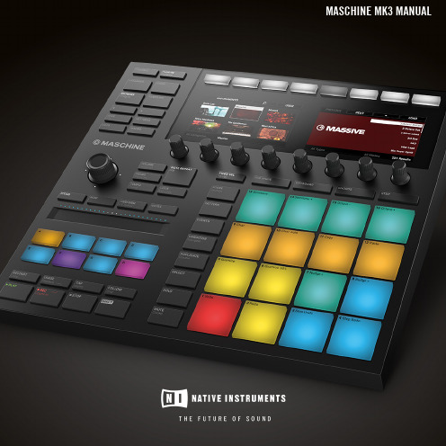
The information in this document is subject to change without notice and does not represent a commitment on the part of Native Instruments GmbH. The software described by this docu-ment is subject to a License Agreement and may not be copied to other media. No part of this publication may be copied, reproduced or otherwise transmitted or recorded, for any purpose, without prior written permission by Native Instruments GmbH, hereinafter referred to as Native Instruments.“Native Instruments”, “NI” and associated logos are (registered) trademarks of Native Instru-ments GmbH.ASIO, VST, HALion and Cubase are registered trademarks of Steinberg Media Technologies GmbH.All other product and company names are trademarks™ or registered® trademarks of their re-spective holders. Use of them does not imply any affiliation with or endorsement by them.Document authored by: David Gover and Nico Sidi.Software version: 2.8 (02/2019)Hardware version: MASCHINE MK3Special thanks to the Beta Test Team, who were invaluable not just in tracking down bugs, but in making this a better product.NATIVE INSTRUMENTS GmbH Schlesische Str. 29-30D-10997 Berlin Germanywww.native-instruments.de NATIVE INSTRUMENTS North America, Inc. 6725 Sunset Boulevard5th FloorLos Angeles, CA 90028USANATIVE INSTRUMENTS K.K.YO Building 3FJingumae 6-7-15, Shibuya-ku, Tokyo 150-0001Japanwww.native-instruments.co.jp NATIVE INSTRUMENTS UK Limited 18 Phipp StreetLondon EC2A 4NUUKNATIVE INSTRUMENTS FRANCE SARL 113 Rue Saint-Maur75011 ParisFrance SHENZHEN NATIVE INSTRUMENTS COMPANY Limited 5F, Shenzhen Zimao Center111 Taizi Road, Nanshan District, Shenzhen, GuangdongChina© NATIVE INSTRUMENTS GmbH, 2019. All rights reserved.Table of Contents1Welcome to MASCHINE (25)1.1MASCHINE Documentation (26)1.2Document Conventions (27)1.3New Features in MASCHINE 2.8 (29)1.4New Features in MASCHINE 2.7.10 (31)1.5New Features in MASCHINE 2.7.8 (31)1.6New Features in MASCHINE 2.7.7 (32)1.7New Features in MASCHINE 2.7.4 (33)1.8New Features in MASCHINE 2.7.3 (36)2Quick Reference (38)2.1Using Your Controller (38)2.1.1Controller Modes and Mode Pinning (38)2.1.2Controlling the Software Views from Your Controller (40)2.2MASCHINE Project Overview (43)2.2.1Sound Content (44)2.2.2Arrangement (45)2.3MASCHINE Hardware Overview (48)2.3.1MASCHINE Hardware Overview (48)2.3.1.1Control Section (50)2.3.1.2Edit Section (53)2.3.1.3Performance Section (54)2.3.1.4Group Section (56)2.3.1.5Transport Section (56)2.3.1.6Pad Section (58)2.3.1.7Rear Panel (63)2.4MASCHINE Software Overview (65)2.4.1Header (66)2.4.2Browser (68)2.4.3Arranger (70)2.4.4Control Area (73)2.4.5Pattern Editor (74)3Basic Concepts (76)3.1Important Names and Concepts (76)3.2Adjusting the MASCHINE User Interface (79)3.2.1Adjusting the Size of the Interface (79)3.2.2Switching between Ideas View and Song View (80)3.2.3Showing/Hiding the Browser (81)3.2.4Showing/Hiding the Control Lane (81)3.3Common Operations (82)3.3.1Using the 4-Directional Push Encoder (82)3.3.2Pinning a Mode on the Controller (83)3.3.3Adjusting Volume, Swing, and Tempo (84)3.3.4Undo/Redo (87)3.3.5List Overlay for Selectors (89)3.3.6Zoom and Scroll Overlays (90)3.3.7Focusing on a Group or a Sound (91)3.3.8Switching Between the Master, Group, and Sound Level (96)3.3.9Navigating Channel Properties, Plug-ins, and Parameter Pages in the Control Area.973.3.9.1Extended Navigate Mode on Your Controller (102)3.3.10Navigating the Software Using the Controller (105)3.3.11Using Two or More Hardware Controllers (106)3.3.12Touch Auto-Write Option (108)3.4Native Kontrol Standard (110)3.5Stand-Alone and Plug-in Mode (111)3.5.1Differences between Stand-Alone and Plug-in Mode (112)3.5.2Switching Instances (113)3.5.3Controlling Various Instances with Different Controllers (114)3.6Host Integration (114)3.6.1Setting up Host Integration (115)3.6.1.1Setting up Ableton Live (macOS) (115)3.6.1.2Setting up Ableton Live (Windows) (116)3.6.1.3Setting up Apple Logic Pro X (116)3.6.2Integration with Ableton Live (117)3.6.3Integration with Apple Logic Pro X (119)3.7Preferences (120)3.7.1Preferences – General Page (121)3.7.2Preferences – Audio Page (126)3.7.3Preferences – MIDI Page (130)3.7.4Preferences – Default Page (133)3.7.5Preferences – Library Page (137)3.7.6Preferences – Plug-ins Page (145)3.7.7Preferences – Hardware Page (150)3.7.8Preferences – Colors Page (154)3.8Integrating MASCHINE into a MIDI Setup (156)3.8.1Connecting External MIDI Equipment (156)3.8.2Sync to External MIDI Clock (157)3.8.3Send MIDI Clock (158)3.9Syncing MASCHINE using Ableton Link (159)3.9.1Connecting to a Network (159)3.9.2Joining and Leaving a Link Session (159)3.10Using a Pedal with the MASCHINE Controller (160)3.11File Management on the MASCHINE Controller (161)4Browser (163)4.1Browser Basics (163)4.1.1The MASCHINE Library (163)4.1.2Browsing the Library vs. Browsing Your Hard Disks (164)4.2Searching and Loading Files from the Library (165)4.2.1Overview of the Library Pane (165)4.2.2Selecting or Loading a Product and Selecting a Bank from the Browser (170)4.2.2.1[MK3] Browsing by Product Category Using the Controller (174)4.2.2.2[MK3] Browsing by Product Vendor Using the Controller (174)4.2.3Selecting a Product Category, a Product, a Bank, and a Sub-Bank (175)4.2.3.1Selecting a Product Category, a Product, a Bank, and a Sub-Bank on theController (179)4.2.4Selecting a File Type (180)4.2.5Choosing Between Factory and User Content (181)4.2.6Selecting Type and Character Tags (182)4.2.7List and Tag Overlays in the Browser (186)4.2.8Performing a Text Search (188)4.2.9Loading a File from the Result List (188)4.3Additional Browsing Tools (193)4.3.1Loading the Selected Files Automatically (193)4.3.2Auditioning Instrument Presets (195)4.3.3Auditioning Samples (196)4.3.4Loading Groups with Patterns (197)4.3.5Loading Groups with Routing (198)4.3.6Displaying File Information (198)4.4Using Favorites in the Browser (199)4.5Editing the Files’ Tags and Properties (203)4.5.1Attribute Editor Basics (203)4.5.2The Bank Page (205)4.5.3The Types and Characters Pages (205)4.5.4The Properties Page (208)4.6Loading and Importing Files from Your File System (209)4.6.1Overview of the FILES Pane (209)4.6.2Using Favorites (211)4.6.3Using the Location Bar (212)4.6.4Navigating to Recent Locations (213)4.6.5Using the Result List (214)4.6.6Importing Files to the MASCHINE Library (217)4.7Locating Missing Samples (219)4.8Using Quick Browse (221)5Managing Sounds, Groups, and Your Project (225)5.1Overview of the Sounds, Groups, and Master (225)5.1.1The Sound, Group, and Master Channels (226)5.1.2Similarities and Differences in Handling Sounds and Groups (227)5.1.3Selecting Multiple Sounds or Groups (228)5.2Managing Sounds (233)5.2.1Loading Sounds (235)5.2.2Pre-listening to Sounds (236)5.2.3Renaming Sound Slots (237)5.2.4Changing the Sound’s Color (237)5.2.5Saving Sounds (239)5.2.6Copying and Pasting Sounds (241)5.2.7Moving Sounds (244)5.2.8Resetting Sound Slots (245)5.3Managing Groups (247)5.3.1Creating Groups (248)5.3.2Loading Groups (249)5.3.3Renaming Groups (251)5.3.4Changing the Group’s Color (251)5.3.5Saving Groups (253)5.3.6Copying and Pasting Groups (255)5.3.7Reordering Groups (258)5.3.8Deleting Groups (259)5.4Exporting MASCHINE Objects and Audio (260)5.4.1Saving a Group with its Samples (261)5.4.2Saving a Project with its Samples (262)5.4.3Exporting Audio (264)5.5Importing Third-Party File Formats (270)5.5.1Loading REX Files into Sound Slots (270)5.5.2Importing MPC Programs to Groups (271)6Playing on the Controller (275)6.1Adjusting the Pads (275)6.1.1The Pad View in the Software (275)6.1.2Choosing a Pad Input Mode (277)6.1.3Adjusting the Base Key (280)6.1.4Using Choke Groups (282)6.1.5Using Link Groups (284)6.2Adjusting the Key, Choke, and Link Parameters for Multiple Sounds (286)6.3Playing Tools (287)6.3.1Mute and Solo (288)6.3.2Choke All Notes (292)6.3.3Groove (293)6.3.4Level, Tempo, Tune, and Groove Shortcuts on Your Controller (295)6.3.5Tap Tempo (299)6.4Performance Features (300)6.4.1Overview of the Perform Features (300)6.4.2Selecting a Scale and Creating Chords (303)6.4.3Scale and Chord Parameters (303)6.4.4Creating Arpeggios and Repeated Notes (316)6.4.5Swing on Note Repeat / Arp Output (321)6.5Using Lock Snapshots (322)6.5.1Creating a Lock Snapshot (322)6.5.2Using Extended Lock (323)6.5.3Updating a Lock Snapshot (323)6.5.4Recalling a Lock Snapshot (324)6.5.5Morphing Between Lock Snapshots (324)6.5.6Deleting a Lock Snapshot (325)6.5.7Triggering Lock Snapshots via MIDI (326)6.6Using the Smart Strip (327)6.6.1Pitch Mode (328)6.6.2Modulation Mode (328)6.6.3Perform Mode (328)6.6.4Notes Mode (329)7Working with Plug-ins (330)7.1Plug-in Overview (330)7.1.1Plug-in Basics (330)7.1.2First Plug-in Slot of Sounds: Choosing the Sound’s Role (334)7.1.3Loading, Removing, and Replacing a Plug-in (335)7.1.3.1Browser Plug-in Slot Selection (341)7.1.4Adjusting the Plug-in Parameters (344)7.1.5Bypassing Plug-in Slots (344)7.1.6Using Side-Chain (346)7.1.7Moving Plug-ins (346)7.1.8Alternative: the Plug-in Strip (348)7.1.9Saving and Recalling Plug-in Presets (348)7.1.9.1Saving Plug-in Presets (349)7.1.9.2Recalling Plug-in Presets (350)7.1.9.3Removing a Default Plug-in Preset (351)7.2The Sampler Plug-in (352)7.2.1Page 1: Voice Settings / Engine (354)7.2.2Page 2: Pitch / Envelope (356)7.2.3Page 3: FX / Filter (359)7.2.4Page 4: Modulation (361)7.2.5Page 5: LFO (363)7.2.6Page 6: Velocity / Modwheel (365)7.3Using Native Instruments and External Plug-ins (367)7.3.1Opening/Closing Plug-in Windows (367)7.3.2Using the VST/AU Plug-in Parameters (370)7.3.3Setting Up Your Own Parameter Pages (371)7.3.4Using VST/AU Plug-in Presets (376)7.3.5Multiple-Output Plug-ins and Multitimbral Plug-ins (378)8Using the Audio Plug-in (380)8.1Loading a Loop into the Audio Plug-in (384)8.2Editing Audio in the Audio Plug-in (385)8.3Using Loop Mode (386)8.4Using Gate Mode (388)9Using the Drumsynths (390)9.1Drumsynths – General Handling (391)9.1.1Engines: Many Different Drums per Drumsynth (391)9.1.2Common Parameter Organization (391)9.1.3Shared Parameters (394)9.1.4Various Velocity Responses (394)9.1.5Pitch Range, Tuning, and MIDI Notes (394)9.2The Kicks (395)9.2.1Kick – Sub (397)9.2.2Kick – Tronic (399)9.2.3Kick – Dusty (402)9.2.4Kick – Grit (403)9.2.5Kick – Rasper (406)9.2.6Kick – Snappy (407)9.2.7Kick – Bold (409)9.2.8Kick – Maple (411)9.2.9Kick – Push (412)9.3The Snares (414)9.3.1Snare – Volt (416)9.3.2Snare – Bit (418)9.3.3Snare – Pow (420)9.3.4Snare – Sharp (421)9.3.5Snare – Airy (423)9.3.6Snare – Vintage (425)9.3.7Snare – Chrome (427)9.3.8Snare – Iron (429)9.3.9Snare – Clap (431)9.3.10Snare – Breaker (433)9.4The Hi-hats (435)9.4.1Hi-hat – Silver (436)9.4.2Hi-hat – Circuit (438)9.4.3Hi-hat – Memory (440)9.4.4Hi-hat – Hybrid (442)9.4.5Creating a Pattern with Closed and Open Hi-hats (444)9.5The Toms (445)9.5.1Tom – Tronic (447)9.5.2Tom – Fractal (449)9.5.3Tom – Floor (453)9.5.4Tom – High (455)9.6The Percussions (456)9.6.1Percussion – Fractal (458)9.6.2Percussion – Kettle (461)9.6.3Percussion – Shaker (463)9.7The Cymbals (467)9.7.1Cymbal – Crash (469)9.7.2Cymbal – Ride (471)10Using the Bass Synth (474)10.1Bass Synth – General Handling (475)10.1.1Parameter Organization (475)10.1.2Bass Synth Parameters (477)11Working with Patterns (479)11.1Pattern Basics (479)11.1.1Pattern Editor Overview (480)11.1.2Navigating the Event Area (486)11.1.3Following the Playback Position in the Pattern (488)11.1.4Jumping to Another Playback Position in the Pattern (489)11.1.5Group View and Keyboard View (491)11.1.6Adjusting the Arrange Grid and the Pattern Length (493)11.1.7Adjusting the Step Grid and the Nudge Grid (497)11.2Recording Patterns in Real Time (501)11.2.1Recording Your Patterns Live (501)11.2.2The Record Prepare Mode (504)11.2.3Using the Metronome (505)11.2.4Recording with Count-in (506)11.2.5Quantizing while Recording (508)11.3Recording Patterns with the Step Sequencer (508)11.3.1Step Mode Basics (508)11.3.2Editing Events in Step Mode (511)11.3.3Recording Modulation in Step Mode (513)11.4Editing Events (514)11.4.1Editing Events with the Mouse: an Overview (514)11.4.2Creating Events/Notes (517)11.4.3Selecting Events/Notes (518)11.4.4Editing Selected Events/Notes (526)11.4.5Deleting Events/Notes (532)11.4.6Cut, Copy, and Paste Events/Notes (535)11.4.7Quantizing Events/Notes (538)11.4.8Quantization While Playing (540)11.4.9Doubling a Pattern (541)11.4.10Adding Variation to Patterns (541)11.5Recording and Editing Modulation (546)11.5.1Which Parameters Are Modulatable? (547)11.5.2Recording Modulation (548)11.5.3Creating and Editing Modulation in the Control Lane (550)11.6Creating MIDI Tracks from Scratch in MASCHINE (555)11.7Managing Patterns (557)11.7.1The Pattern Manager and Pattern Mode (558)11.7.2Selecting Patterns and Pattern Banks (560)11.7.3Creating Patterns (563)11.7.4Deleting Patterns (565)11.7.5Creating and Deleting Pattern Banks (566)11.7.6Naming Patterns (568)11.7.7Changing the Pattern’s Color (570)11.7.8Duplicating, Copying, and Pasting Patterns (571)11.7.9Moving Patterns (574)11.7.10Adjusting Pattern Length in Fine Increments (575)11.8Importing/Exporting Audio and MIDI to/from Patterns (576)11.8.1Exporting Audio from Patterns (576)11.8.2Exporting MIDI from Patterns (577)11.8.3Importing MIDI to Patterns (580)12Audio Routing, Remote Control, and Macro Controls (589)12.1Audio Routing in MASCHINE (590)12.1.1Sending External Audio to Sounds (591)12.1.2Configuring the Main Output of Sounds and Groups (596)12.1.3Setting Up Auxiliary Outputs for Sounds and Groups (601)12.1.4Configuring the Master and Cue Outputs of MASCHINE (605)12.1.5Mono Audio Inputs (610)12.1.5.1Configuring External Inputs for Sounds in Mix View (611)12.2Using MIDI Control and Host Automation (614)12.2.1Triggering Sounds via MIDI Notes (615)12.2.2Triggering Scenes via MIDI (622)12.2.3Controlling Parameters via MIDI and Host Automation (623)12.2.4Selecting VST/AU Plug-in Presets via MIDI Program Change (631)12.2.5Sending MIDI from Sounds (632)12.3Creating Custom Sets of Parameters with the Macro Controls (636)12.3.1Macro Control Overview (637)12.3.2Assigning Macro Controls Using the Software (638)12.3.3Assigning Macro Controls Using the Controller (644)13Controlling Your Mix (646)13.1Mix View Basics (646)13.1.1Switching between Arrange View and Mix View (646)13.1.2Mix View Elements (647)13.2The Mixer (649)13.2.1Displaying Groups vs. Displaying Sounds (650)13.2.2Adjusting the Mixer Layout (652)13.2.3Selecting Channel Strips (653)13.2.4Managing Your Channels in the Mixer (654)13.2.5Adjusting Settings in the Channel Strips (656)13.2.6Using the Cue Bus (660)13.3The Plug-in Chain (662)13.4The Plug-in Strip (663)13.4.1The Plug-in Header (665)13.4.2Panels for Drumsynths and Internal Effects (667)13.4.3Panel for the Sampler (668)13.4.4Custom Panels for Native Instruments Plug-ins (671)13.4.5Undocking a Plug-in Panel (Native Instruments and External Plug-ins Only) (675)13.5Controlling Your Mix from the Controller (677)13.5.1Navigating Your Channels in Mix Mode (678)13.5.2Adjusting the Level and Pan in Mix Mode (679)13.5.3Mute and Solo in Mix Mode (680)13.5.4Plug-in Icons in Mix Mode (680)14Using Effects (681)14.1Applying Effects to a Sound, a Group or the Master (681)14.1.1Adding an Effect (681)14.1.2Other Operations on Effects (690)14.1.3Using the Side-Chain Input (692)14.2Applying Effects to External Audio (695)14.2.1Step 1: Configure MASCHINE Audio Inputs (695)14.2.2Step 2: Set up a Sound to Receive the External Input (698)14.2.3Step 3: Load an Effect to Process an Input (700)14.3Creating a Send Effect (701)14.3.1Step 1: Set Up a Sound or Group as Send Effect (702)14.3.2Step 2: Route Audio to the Send Effect (706)14.3.3 A Few Notes on Send Effects (708)14.4Creating Multi-Effects (709)15Effect Reference (712)15.1Dynamics (713)15.1.1Compressor (713)15.1.2Gate (717)15.1.3Transient Master (721)15.1.4Limiter (723)15.1.5Maximizer (727)15.2Filtering Effects (730)15.2.1EQ (730)15.2.2Filter (733)15.2.3Cabinet (737)15.3Modulation Effects (738)15.3.1Chorus (738)15.3.2Flanger (740)15.3.3FM (742)15.3.4Freq Shifter (743)15.3.5Phaser (745)15.4Spatial and Reverb Effects (747)15.4.1Ice (747)15.4.2Metaverb (749)15.4.3Reflex (750)15.4.4Reverb (Legacy) (752)15.4.5Reverb (754)15.4.5.1Reverb Room (754)15.4.5.2Reverb Hall (757)15.4.5.3Plate Reverb (760)15.5Delays (762)15.5.1Beat Delay (762)15.5.2Grain Delay (765)15.5.3Grain Stretch (767)15.5.4Resochord (769)15.6Distortion Effects (771)15.6.1Distortion (771)15.6.2Lofi (774)15.6.3Saturator (775)15.7Perform FX (779)15.7.1Filter (780)15.7.2Flanger (782)15.7.3Burst Echo (785)15.7.4Reso Echo (787)15.7.5Ring (790)15.7.6Stutter (792)15.7.7Tremolo (795)15.7.8Scratcher (798)16Working with the Arranger (801)16.1Arranger Basics (801)16.1.1Navigating Song View (804)16.1.2Following the Playback Position in Your Project (806)16.1.3Performing with Scenes and Sections using the Pads (807)16.2Using Ideas View (811)16.2.1Scene Overview (811)16.2.2Creating Scenes (813)16.2.3Assigning and Removing Patterns (813)16.2.4Selecting Scenes (817)16.2.5Deleting Scenes (818)16.2.6Creating and Deleting Scene Banks (820)16.2.7Clearing Scenes (820)16.2.8Duplicating Scenes (821)16.2.9Reordering Scenes (822)16.2.10Making Scenes Unique (824)16.2.11Appending Scenes to Arrangement (825)16.2.12Naming Scenes (826)16.2.13Changing the Color of a Scene (827)16.3Using Song View (828)16.3.1Section Management Overview (828)16.3.2Creating Sections (833)16.3.3Assigning a Scene to a Section (834)16.3.4Selecting Sections and Section Banks (835)16.3.5Reorganizing Sections (839)16.3.6Adjusting the Length of a Section (840)16.3.6.1Adjusting the Length of a Section Using the Software (841)16.3.6.2Adjusting the Length of a Section Using the Controller (843)16.3.7Clearing a Pattern in Song View (843)16.3.8Duplicating Sections (844)16.3.8.1Making Sections Unique (845)16.3.9Removing Sections (846)16.3.10Renaming Scenes (848)16.3.11Clearing Sections (849)16.3.12Creating and Deleting Section Banks (850)16.3.13Working with Patterns in Song view (850)16.3.13.1Creating a Pattern in Song View (850)16.3.13.2Selecting a Pattern in Song View (850)16.3.13.3Clearing a Pattern in Song View (851)16.3.13.4Renaming a Pattern in Song View (851)16.3.13.5Coloring a Pattern in Song View (851)16.3.13.6Removing a Pattern in Song View (852)16.3.13.7Duplicating a Pattern in Song View (852)16.3.14Enabling Auto Length (852)16.3.15Looping (853)16.3.15.1Setting the Loop Range in the Software (854)16.4Playing with Sections (855)16.4.1Jumping to another Playback Position in Your Project (855)16.5Triggering Sections or Scenes via MIDI (856)16.6The Arrange Grid (858)16.7Quick Grid (860)17Sampling and Sample Mapping (862)17.1Opening the Sample Editor (862)17.2Recording Audio (863)17.2.1Opening the Record Page (863)17.2.2Selecting the Source and the Recording Mode (865)17.2.3Arming, Starting, and Stopping the Recording (868)17.2.5Using the Footswitch for Recording Audio (871)17.2.6Checking Your Recordings (872)17.2.7Location and Name of Your Recorded Samples (876)17.3Editing a Sample (876)17.3.1Using the Edit Page (877)17.3.2Audio Editing Functions (882)17.4Slicing a Sample (890)17.4.1Opening the Slice Page (891)17.4.2Adjusting the Slicing Settings (893)17.4.3Live Slicing (898)17.4.3.1Live Slicing Using the Controller (898)17.4.3.2Delete All Slices (899)17.4.4Manually Adjusting Your Slices (899)17.4.5Applying the Slicing (906)17.5Mapping Samples to Zones (912)17.5.1Opening the Zone Page (912)17.5.2Zone Page Overview (913)17.5.3Selecting and Managing Zones in the Zone List (915)17.5.4Selecting and Editing Zones in the Map View (920)17.5.5Editing Zones in the Sample View (924)17.5.6Adjusting the Zone Settings (927)17.5.7Adding Samples to the Sample Map (934)18Appendix: Tips for Playing Live (937)18.1Preparations (937)18.1.1Focus on the Hardware (937)18.1.2Customize the Pads of the Hardware (937)18.1.3Check Your CPU Power Before Playing (937)18.1.4Name and Color Your Groups, Patterns, Sounds and Scenes (938)18.1.5Consider Using a Limiter on Your Master (938)18.1.6Hook Up Your Other Gear and Sync It with MIDI Clock (938)18.1.7Improvise (938)18.2Basic Techniques (938)18.2.1Use Mute and Solo (938)18.2.2Use Scene Mode and Tweak the Loop Range (939)18.2.3Create Variations of Your Drum Patterns in the Step Sequencer (939)18.2.4Use Note Repeat (939)18.2.5Set Up Your Own Multi-effect Groups and Automate Them (939)18.3Special Tricks (940)18.3.1Changing Pattern Length for Variation (940)18.3.2Using Loops to Cycle Through Samples (940)18.3.3Using Loops to Cycle Through Samples (940)18.3.4Load Long Audio Files and Play with the Start Point (940)19Troubleshooting (941)19.1Knowledge Base (941)19.2Technical Support (941)19.3Registration Support (942)19.4User Forum (942)20Glossary (943)Index (951)1Welcome to MASCHINEThank you for buying MASCHINE!MASCHINE is a groove production studio that implements the familiar working style of classi-cal groove boxes along with the advantages of a computer based system. MASCHINE is ideal for making music live, as well as in the studio. It’s the hands-on aspect of a dedicated instru-ment, the MASCHINE hardware controller, united with the advanced editing features of the MASCHINE software.Creating beats is often not very intuitive with a computer, but using the MASCHINE hardware controller to do it makes it easy and fun. You can tap in freely with the pads or use Note Re-peat to jam along. Alternatively, build your beats using the step sequencer just as in classic drum machines.Patterns can be intuitively combined and rearranged on the fly to form larger ideas. You can try out several different versions of a song without ever having to stop the music.Since you can integrate it into any sequencer that supports VST, AU, or AAX plug-ins, you can reap the benefits in almost any software setup, or use it as a stand-alone application. You can sample your own material, slice loops and rearrange them easily.However, MASCHINE is a lot more than an ordinary groovebox or sampler: it comes with an inspiring 7-gigabyte library, and a sophisticated, yet easy to use tag-based Browser to give you instant access to the sounds you are looking for.What’s more, MASCHINE provides lots of options for manipulating your sounds via internal ef-fects and other sound-shaping possibilities. You can also control external MIDI hardware and 3rd-party software with the MASCHINE hardware controller, while customizing the functions of the pads, knobs and buttons according to your needs utilizing the included Controller Editor application. We hope you enjoy this fantastic instrument as much as we do. Now let’s get go-ing!—The MASCHINE team at Native Instruments.MASCHINE Documentation1.1MASCHINE DocumentationNative Instruments provide many information sources regarding MASCHINE. The main docu-ments should be read in the following sequence:1.MASCHINE Getting Started: This document provides a practical approach to MASCHINE viaa set of tutorials covering easy and more advanced tasks in order to help you familiarizeyourself with MASCHINE.2.MASCHINE Manual (this document): The MASCHINE Manual provides you with a compre-hensive description of all MASCHINE software and hardware features.Additional documentation sources provide you with details on more specific topics:▪Controller Editor Manual: Besides using your MASCHINE hardware controller together withits dedicated MASCHINE software, you can also use it as a powerful and highly versatileMIDI controller to pilot any other MIDI-capable application or device. This is made possibleby the Controller Editor software, an application that allows you to precisely define all MIDIassignments for your MASCHINE controller. The Controller Editor was installed during theMASCHINE installation procedure. For more information on this, please refer to the Con-troller Editor Manual available as a PDF file via the Help menu of Controller Editor.▪Online Support Videos: You can find a number of support videos on The Official Native In-struments Support Channel under the following URL: https:///NIsupport-EN. We recommend that you follow along with these instructions while the respective ap-plication is running on your computer.Other Online Resources:If you are experiencing problems related to your Native Instruments product that the supplied documentation does not cover, there are several ways of getting help:▪Knowledge Base▪User Forum▪Technical Support▪Registration SupportYou will find more information on these subjects in the chapter Troubleshooting.1.2Document ConventionsThis section introduces you to the signage and text highlighting used in this manual. This man-ual uses particular formatting to point out special facts and to warn you of potential issues. The icons introducing these notes let you see what kind of information is to be expected:This document uses particular formatting to point out special facts and to warn you of poten-tial issues. The icons introducing the following notes let you see what kind of information can be expected:Furthermore, the following formatting is used:▪Text appearing in (drop-down) menus (such as Open…, Save as… etc.) in the software and paths to locations on your hard disk or other storage devices is printed in italics.▪Text appearing elsewhere (labels of buttons, controls, text next to checkboxes etc.) in the software is printed in blue. Whenever you see this formatting applied, you will find the same text appearing somewhere on the screen.▪Text appearing on the displays of the controller is printed in light grey. Whenever you see this formatting applied, you will find the same text on a controller display.▪Text appearing on labels of the hardware controller is printed in orange. Whenever you see this formatting applied, you will find the same text on the controller.▪Important names and concepts are printed in bold.▪References to keys on your computer’s keyboard you’ll find put in square brackets (e.g.,“Press [Shift] + [Enter]”).►Single instructions are introduced by this play button type arrow.→Results of actions are introduced by this smaller arrow.Naming ConventionThroughout the documentation we will refer to MASCHINE controller (or just controller) as the hardware controller and MASCHINE software as the software installed on your computer.The term “effect” will sometimes be abbreviated as “FX” when referring to elements in the MA-SCHINE software and hardware. These terms have the same meaning.Button Combinations and Shortcuts on Your ControllerMost instructions will use the “+” sign to indicate buttons (or buttons and pads) that must be pressed simultaneously, starting with the button indicated first. E.g., an instruction such as:“Press SHIFT + PLAY”means:1.Press and hold SHIFT.2.While holding SHIFT, press PLAY and release it.3.Release SHIFT.Unlabeled Buttons on the ControllerThe buttons and knobs above and below the displays on your MASCHINE controller do not have labels.。
Sun Fire 高端和中等系统 UltraSPARC IV CPU Memory 板升级要求说明书

CAUTIONREAD ME FIRST Failure to follow these procedures will cause your system to not recognize the new CPU/Memory board.Firmware on all boards and assemblies must be at the same level as the new CPU/Memory board.Sun Fire ™ High-End and Midrange Systems UltraSPARC ® IV CPU/Memory Board Upgrade RequirementsSun Fire E25K/E20K SystemsSun Fire 15K/12K SystemsSun Fire E6900/E4900 SystemsSun Fire 6800/4800 Systems!Note –If sold as a field-replaceable unit (FRU),a CPU/Memory board is for replacement use only .FRUs must not be used to upgrade CPU performance in systems.Such usage can violate United States export regulations.Note –UltraSPARC ®IV CPU/Memory boards are not supported in Sun Fire™4810/3800systems.Only earlier versions of CPU/Memory boards are supported in Sun Fire 4810/3800systems.Additional Hardware Requirements for Sun Fire 6800/4800SystemsSun Fire™6800/4800systems require additional hardware upgrades if you upgrade to UltraSPARC IV CPU/Memory boards:■Sun Fire 6800system:upgrade all six power supplies (PS0through PS5)to part number 300-1595-xx.Also install an EMI gasket kit,part number 560-2755-xx in the card cage.■Sun Fire 4800system:upgrade all three power supplies (PS0through PS2)to part number 300-1596-xx.Also upgrade the fan trays:FT0(bottom left)to part number 540-5998-xx,FT1(top)to part number 540-5997-xx,and FT2(bottom right)to part number 540-5999-xx.Caution –The Sun Fire 6800/4800system might shut down if you do not install the additional upgrades that are required for theUltraSPARC IV CPU/Memory boards.♦To determine if the hardware upgrades are already installed:■Use the system controller showfru command to see the manufacturing record of FRU part numbers.This command is available with firmware version 5.18.1and later.■Alternatively,you can find the part numbers on the device labels.Firmware and OS Minimum RequirementsNote –If your system requires a software upgrade and a firmware upgrade,upgrade the firmware first.Upgrade the software second.Install new CPU/Memory boards only after you have upgraded the firmware and software.schostname :SC>showfru -r manrSun Fire E6900/E4900systems and upgraded Sun Fire6800/4800systems require these versions:■Firmware level5.18.1or subsequent compatible versions.■Solaris82/04Operating System or subsequent compatible versions. Sun Fire E25K/E20K systems and upgraded Sun Fire15K/12K systems require these versions:■SMS1.4.1or subsequent compatible versions.■SMS1.4.1patch1178660-04.■Solaris82/04Operating System or subsequent compatible versions. Note–Patches can be found at:Installation information,Release Notes and README files are included in the patch download.Checking Firmware on Boards and Assemblies♦When installing new CPU/Memory boards,use the showboards command to determine if the firmware needs to be updated:schostname:SC>showboards -p promsIf an update is required,use the system controller flashupdate command as shown below.Upgrading FirmwareUpgrade thefirmware and real time operating system(RTOS)images only if the image to install is different than the image that is already installed.♦To install the firmware upgrade,use the flashupdate command for your specific system.■For Sun Fire E6900/E4900or Sun Fire6800/4800systems:schostname:SC> flashupdate -f URL all rtos■For Sun Fire E25K/E20K or Sun Fire15K/12K systems:schostname:SC> flashupdate -f URL -d domain_idFor details on using the flashupdate command,refer to the system controller manual for your product.Sun Microsystems, Inc.Part No. 819-1279-10, Rev. AJanuary 2005Accessing Sun DocumentationYou can view,print,or purchase a broad selection of Sun documentation,including localized versions,at:/documentationContacting Sun Technical SupportIf you have technical questions about this product that are not answered in this document,go to:/service/contactingSun Welcomes Your CommentsSun is interested in improving its documentation and welcomes your comments and suggestions.You can submit your comments by going to:/hwdocs/feedbackPlease include the title and part number of your document with your feedback:Sun Fire High-End and Midrange Systems UltraSPARC IV CPU/Memory Board Upgrade Requirements ,part number 819-1279-10Copyright 2004Sun Microsystems,Inc.All rights e is subject to license terms.Third-party software,including font technology,is copyrighted and licensed from Sun suppliers.Portions may be derived from Berkeley BSD systems,licensed from U.of CA.Sun,Sun Microsystems,the Sun logo,and Solaris are trademarks or registered trademarks of Sun Microsystems,Inc.in the U.S.and in other countries.All SPARC trademarks are used under license and are trademarks or registered trademarks of SPARC International,Inc.in the U.S.and in other ernment Rights—Commercial ernment users are subject to the Sun Microsystems,Inc.standard license agreement and applicable provisions of the FAR and its supplements.Copyright 2004Sun Microsystems,Inc.Tous droits réservés.Distribuépar des licences qui en restreignent l’utilisation.Le logiciel détenu par des tiers,et qui comprend la technologie relative aux polices de caractères,est protégépar un copyright et licenciépar des fournisseurs de Sun.Des parties de ce produit pourront être dérivées des systèmes Berkeley BSD licenciés par l’Universitéde Californie.Sun,Sun Microsystems,le logo Sun,et Solaris sont des marques de fabrique ou des marques déposées de Sun Microsystems,Inc.aux Etats-Unis et dans d’autres pays.Toutes les marques SPARC sont utilisées sous licence et sont des marques de fabrique ou des marques déposées de SPARC International,Inc.aux Etats-Unis et dans d’autres pays.。
施耐德电气低压配电产品选型指南说明书
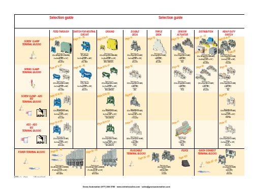
ABB EntrelecSommaireBU0402061SNC 160 003 C0205SummarySelection guide ....................................................................................page 1Screw clamp ........................................................................................page 2Feed through and ground terminal blocks .......................................................page 2 - 5 to 10Single pole, multiclamp terminal blocks..........................................................................page 4Feed through terminal blocks - Double-deck................................................................page 11Feed through terminal blocks - Triple-deck...................................................................page 12Three level sensor, terminal blocks without ground connection...................................page 13Three level sensor, terminal blocks with ground connection ........................................page 14Terminal blocks for distribution boxes, double deck + protection .......................page 15 - 16Interruptible terminal blocks for neutral circuit......................................................page 17 - 18Distribution : phase, ground terminal blocks .......................................................page 19 to 21Single pole or four pole distribution blocks..........................................................page 22 to 24Heavy duty switch terminal blocks with blade......................................................page 25 - 26Heavy duty switch terminal blocks with push-turn knob..............................................page 26Heavy duty switch terminal blocks with contact control pull lever...............................page 29Heavy duty switch terminal blocks with blade - Double-deck .....................................page 27Fuse holder terminal blocks for 5x20 mm (.197x.787 in.) and 5x25 mm (.197x.984 in.)or 6.35x25.4 mm (1/4x1 in.) and 6.35x32 mm (1/4x11/4 in.) fuse s.........................................page 28 - 29Fuse holder terminal blocks for 5x20 mm (.197x.787 in.) and 5x25 mm (.197x.984 in.) fuses -Double-dec k.....................................................................................................................page 27Terminal blocks for test circuits with sliding bridge ......................................................page 30Terminal blocks for metering circuits.............................................................................page 31ESSAILEC terminal blocks.............................................................................................page 32Safety connection terminal blocks ................................................................................page 33Miniblocks for EN 50045 (DIN 46277/2) rail ..........................................................page 34 - 35Spring clamp ......................................................................................page 36Angled terminal blocks - Feed through and ground .....................................................page 36Feed through and ground terminal blocks ...........................................................page 37 to 41Feed through terminal blocks - Double deck ................................................................page 42Terminal blocks for sensors / actuators ........................................................................page 42Terminal blocks for distribution boxes...........................................................................page 43Switch terminal blocks for neutral conductor........................................................page 44 - 45Heavy duty switch terminal blocks with blade..............................................................page 46Fuse holder terminal blocks for 5x20 mm (.197x.787 in.) and 5x25 mm (.197x.984 in.) fuse s....page 47Miniblocks Spring clamp ......................................................................................page 48 to 52ADO - Screw clamp ...........................................................................page 53Feed through and ground terminal blocks ...........................................................page 53 to 56Feed through and ground terminal blocks - Double-deck............................................page 57Heavy duty switch terminal blocks with blade..............................................................page 58Fuse holder terminal blocks for 5x20 mm (.197x.787 in.) and 5x25 mm (.197x.984 in.) fuse s ......page 59 - 60Miniblocks ADO - Screw clamp............................................................................page 61 to 65ADO - ADO .........................................................................................page 66Feed through and ground terminal blocks ...........................................................page 66 to 69Feed through and ground terminal blocks - Double-deck............................................page 70Terminal blocks for sensors / actuators ........................................................................page 71Heavy duty switch terminal blocks with blade..............................................................page 72Fuse holder terminal blocks for 5x20 mm (.197x.787 in.) and 5x25 mm (.197x.984 in.) fuse s ......page 73 - 74Miniblocks ADO - ADO .........................................................................................page 75 to 79Accessories ADO ...........................................................................................................page 80Power terminal blocks .............................................................page 81 to 84Quick-connect terminal blocks .................................................page 85 - 86Terminal blocks for railway applications ................................page 87 to 97Pluggable terminal blocks .....................................................page 98 to 100Accessories......................................................................................page 101Marking..................................................................................page 102 to 104GrossAutomation(877)268-3700··*************************PR30PR3.Z2PR3.G2PR5PR4PR1.Z2Rated wire size :Rated wire size :Rated wire size :Rated wire size :Mounting railsShield terminals forcollector barMarking tableHorizontal Rated wire size :0.5 to 16 mm² (22 to 8 AWG)Rated wire size :Rated wire size :Rated wire size :P a g e t o 29e30 t o 32ag e e3P a ge 8 t o 60a g e6t o 6574P a ge 7 t o 79P a ge 9P a g P a gGrossAutomation(877)268-3700··*************************2ABB Entrelecd010830402051SNC 160 003 C0205MA 2,5/5 - 2.5 mm² blocks - 5 mm .200" spacingAccessoriesGrossAutomation(877)268-3700··*************************3ABB Entrelec D010740402051SNC 160 003 C0205M 4/6 - 4 mm² blocks - 6 mm .238" spacingAccessoriesGrossAutomation(877)268-3700··*************************4ABB EntrelecD011030402051SNC 160 003 C0205M 4/6.3A - 4 mm² blocks - 6 mm .238" spacingM 4/6.4A - 4 mm² blocks - 6 mm .238" spacingGrossAutomation(877)268-3700··*************************5ABB Entrelec D010840402051SNC 160 003 C0205M 6/8 - 6 mm² blocks - 8 mm .315" spacingAccessoriesGrossAutomation(877)268-3700··*************************6ABB EntrelecD010850402051SNC 160 003 C0205M 10/10 - 10 mm² blocks - 10 mm .394" spacingAccessoriesGrossAutomation(877)268-3700··*************************7ABB Entrelec D010860402051SNC 160 003 C0205M 16/12 - 16 mm² blocks - 12 mm .473" spacingAccessoriesGrossAutomation(877)268-3700··*************************8ABB EntrelecD010870402051SNC 160 003 C0205M 35/16 - 35 mm² blocks - 16 mm .630" spacingGrossAutomation(877)268-3700··*************************M 95/26 - 95 mm² blocks - 26 mm 1.02" spacingM 70/22.P - 70 mm² ground block with rail contact - 22 mm .630" spacingSelection35 mm / 1.37"12 mm / 0.47"14-30 Nm / 124-260 Ib.in 1.2-1.4 Nm / 10.6-12.3 Ib.in1000600600415400400577070240 mm 2500 MCM 500 MCM 10 mm 2 6 AWG 6 AWG IEC UL CSANFC DIN0.5 - 160.5 - 100 AWG-600 MCM 2 AWG-500 MCM 50 - 30035 - 24018-6 AWGD 150/31.D10 - 150 mm² blocks - 31 mm 1.22" spacingCharacteristicsD 240/36.D10 - 240 mm² blocks - 36 mm 1.41" spacingSelectionWire size main circuit mm² / AWG VoltageV Current main circuit A Current outputARated wire size main circuit mm² / AWG Rated wire size outputmm² / AWG Wire stripping length main circuit mm / inches Wire stripping length output mm / inches Recommended torque main circuit Nm / Ib.in Recommended torque outputNm / Ib.inSolid Stranded Solid Stranded Wire size output mm² / AWG9.5 mm / .37"0.5-0.8 Nm / 4.4-7.1 Ib.in5003003003220204 mm 212 AWG12 AWG0.2 - 422-12 AWG 22-12 AWG 0.22 - 4IEC ULCSANFC DINCharacteristicsWire size mm² / AWGSolid Stranded D 4/6.T3 - 4 mm² blocks - 6 mm .238" spacingSelectionVoltage V CurrentARated wire sizemm² / AWG Wire stripping length mm / inches Recommended torqueNm / Ib.inM 4/6.T3.P - 4 mm² block - 6 mm .238" spacingD 2,5/6.D - 2.5 mm² blocks - 6 mm .238" spacingD 2,5/6.DL - 2.5 mm² blocks - 6 mm .238" spacingD 2,5/6.DPA1 - 2.5 mm² blocks - 6 mm .238" spacingD 2,5/6.DPAL1 - 2.5 mm² blocks - 6 mm .238" spacingD 4/6... - 4 mm² blocks - 6 mm .238" spacingD 4/6.LNTP - 4 mm² closed blocks - 17.8 mm .700" spacingMA 2,5/5.NT- 2.5 mm² block - 5 mm .200" spacingAccessories**SFB2 : 16 to 35 mm² 6 to 2 AWG H= 3 mm/.12"M 10/10.NT- 10 mm² block - 10 mm .394" spacingAccessories(1) Except for M 35/16 NT (closed block)*SFB1 : 0.5 to 35 mm² 18 to 2 AWG H= 7 mm/.28"**SFB2 : 16 to 35 mm² 6 to 2 AWG H= 3 mm/.12"MB 4/6... - 4 mm² blocks - 6 mm .238" spacingMB 6/8... - 6 mm² blocks - 8 mm .315" spacingMB 10/10... - 10 mm² blocks - 10 mm .394" spacingBRU 125 A - 35 mm² block - 27 mm 1.063" spacingBRU 160 A - 70 mm² block - 35.2 mm 1.388" spacingBRU 250 A - 120 mm² blocks - 44.5 mm 1.752" spacingBRU 400 A - 185 mm² block - 44.5 mm 1.752" spacingAccessoriesAccessoriesBRT 80 A - 16 mm² block - 48 mm 1.89" spacingBRT 125 A - 35 mm² block - 48 mm 1.89" spacingBRT 160 A - 50 mm² block - 50 mm 1.97" spacing9.5 mm / .37"0.5-0.6 Nm / 4.4-5.3 Ib.in4003003002010104 mm 210 AWG 12 AWG 0.5 - 422-10 AWG20-12 AWG0.5 - 2.5IEC ULCSANFC DINMA 2,5/5.SNB - 2.5 mm² blocks - 5 mm .200" spacingCharacteristicsM 4/6.SNB - 4 mm² blocks - 6 mm .238" spacingSelectionWire size mm² / AWGVoltage V CurrentARated wire sizemm² / AWG Wire stripping length mm / inches Recommended torqueNm / Ib.inSolid StrandedM 6/8.SNB - 6 mm² blocks - 8 mm .315" spacing - blade switchingSelectionAccessoriesM 4/8.D2.SF - for fuses 5x20 mm .197x.787 in. and 5x25 mm .197x.984 in. -4 mm² blocks - 8 mm .315" spacingM 4/6.D2.SNBT - 4 mm² blocks - 6 mm .238" spacing - blade switchM 4/8.SF- 4 mm² blocks - 8 mm .315" spacingM 4/8.SFL - 4 mm² blocks - 8 mm .315" spacing12 mm / .472"1.2-1.4 Nm / 10.6-12.3 Ib.in800(1)60060016252510 mm 210 AWG8 AWG0.5 - 1622-10 AWG 22-8 AWG 0.5 - 10IEC ULCSANFC DINCBD2SML 10/13.SF - for fuses 6.35x25.4 mm 1/4x1 in. and 6.35x32 mm 1/4x11/4 in. -10 mm² blocks - 13 mm .512" spacingSelectionAccessoriesCharacteristicsWire size mm² / AWGVoltage V CurrentARated wire sizemm² / AWG Wire stripping length mm / inches Recommended torqueNm / Ib.inSolid Stranded (1) Insulation voltage of terminal block - operating voltage : according to fuse.M 4/6.D2.2S2... - 4 mm² blocks - 6 mm .238" spacing11 mm / .43"0.8-1 Nm / 7.1-8.9 Ib.in50060030306 mm 28 AWG0.5 - 1022-8 AWG0.5 - 6IECULCSANFC DINM 6/8.ST... - 6 mm² blocks - 8 mm .315" spacingCharacteristicsWire size mm² / AWGVoltage V CurrentARated wire sizemm² / AWG Wire stripping length mm / inches Recommended torqueNm / Ib.inSolid Stranded M 6/8.STA - 6 mm² blocks - 8 mm .315" spacing(3)Only for M 6/8.STAM 4/6.ST- 4 mm² blocks - 6 mm .236" spacingBNT...PC...(2) Only for M10/10.ST-SnThe PREM IUM solution for testing the secondary circuits of current or voltage transformers.ESSAILEC, approved by the major electricity utilities, remains the premium choice for the energy market.Implemented in the transformers secondary circuits, ESSAILEC thanks to its intelligent “make before break” design eases and secures any intervention. Cutting the energy supply is avoided with zero risk for the operator.The plug and socket connection cuts cost installation as well as in-situ wiring errors. ESSAILEC is ideal for the wiring of sub-assemblies in the secondary circuits.ESSAILEC terminal blocksProtection relays,Protection relays,Testing :The ESSAILEC socket supplies energy to the protection or counting devices. The insertion of the test plug, which is connected to the measurement equipment, allows the testing of the devices, without perturbing the circuit.ESSAILEC blocks are well adapted to current or voltage measurement :-Current sockets with make before break contacts and pre-wired test plug for current measures-Voltage sockets with open contacts and pre-wired test plug for voltage measures-Up to 4 ammeters or 4 voltmeters connected to the test plugDistributing :The ESSAILEC plug is continuously mounted on the socket to supply current or voltage to secondary circuits sub assemblies.ESSAILEC blocks extreme versatility allow :-Safe current distribution with current socket with mobile contacts since the secondary circuit is not cut when plug is removed-Voltage or polarity distribution with dedicated voltage or polarity socket with closed contactESSAILEC is designed to offer :Great flexibility :-Connection multi contacts « plug and play »-Panel, rail, rack fixed mounting or stand-alone connector -Two wiring technologies, up to 10 mm²Extreme reliability :-Non symmetric blocks -Coding accessories -IP20 design -Locking system -Sealed coverR S T NFor technical characteristics and complete part numbers list, please ask for the ESSAILEC catalog10005006003225254 mm 21.65 mm²12 AWG 13 mm / .51"IECB.SCSANFC DINTS 50-180.5 - 0.8 Nm /4.4 - 7.1 Ib.in0.2 - 422-12 AWG0.22 - 40.5 - 1.50.28 - 1.6580050060041252562.512 AWG 13 mm / .51"0.8 - 1 Nm / 7.1 - 8.9 Ib.inIECB.S CSANFC DINTS 50-180.5 - 1020-12 AWG0.5 - 60.28 - 2.590050060046406510 mm 26 mm² 6 AWG 14 mm / .55"IECB.S UL/CSANFC DINTS 50-181.2 - 1.4 Nm / 10.6 - 12.3 Ib.in0.5 - 1620 - 6 AWG0.5 - 100.28 - 6M 4/6.RS - 4 mm² blocks - 6 mm .238" spacingCharacteristicsWire size mm² / AWGVoltage V CurrentARated wire sizemm² / AWG Wire stripping lengthmm / inches Recommended torque (screw)Nm / Ib.inSolid wire Stranded wire Solid wire Stranded wire Screw clampLugsM 6/8.RS - 6 mm² blocks - 8 mm .315" spacingCharacteristicsWire size mm² / AWGVoltage V CurrentARated wire sizemm² / AWG Wire stripping lengthmm / inches Recommended torque (screw)Nm / Ib.inSolid wire Stranded wire Solid wire Stranded wire Screw clampLugspending M 10/10.RS - 10 mm² blocks - 10 mm .394" spacingCharacteristicsWire size mm² / AWGVoltage V CurrentARated wire sizemm² / AWG Wire stripping lengthmm / inches Recommended torque (screw)Nm / Ib.inSolid wire Stranded wire Solid wire Stranded wire Screw clampLugspending SelectionAccessories(1) Only for block M 4/6.RS (4) For blocks M 4/6.RS and M 6/8.RS(2) Only for block M 6/8.RS(3) Only for block M 10/10.RSDR 1,5/4 - 1.5 mm² blocks - 4 mm .157" spacingDR 1,5/5... - 1.5 mm² blocks - 5 mm .200" spacing。
Disaster Area Designs DMC-

Disaster A rea D esignsDMC-‐3 / D MC-‐3XL O peration M anualRevision 1.00 12/30/12GETTING S TARTEDThe D MC-‐3 / 3XL c ompact M IDI c ontroller p acks l ots o f f unctionality i nto a s mall p ackage. T his functionality d epends o n t he f irmware i nstalled i n t he c ontroller.CONNECTING T HE D MC-‐3 / 3XLThe D MC c ontrollers r equire a p ower s upply t o o perate. T he p edal u ses a s tandard 9V p ower s upply with a 2.1mm p in, c enter n egative. T he c ontroller r equires 24mA m aximum, a nd m ay b e p owered b y most p ower s upplies i ncluding t he V oodoo L abs P edal P ower 2+, V isual S ound 1SPOT, a nd o thers.The D MC c ontroller c ommunicates w ith y our o ther p edals u sing a M IDI c able. T he t ype a nd b rand o f cable i s n ot c ritical – w e u se H OSA c ables a t t he f actory f or t esting.The U SB p ort o n t he D MC c ontroller i s u sed f or f irmware u pdates w ith t he D isaster U ploader application. I t i s n ot u sed d uring n ormal o peration. W hen t he U SB c onnection i s i n u se, t he D MC controller i s p owered b y t he U SB c onnection. T he M IDI a nd p ower c ables m ay s afely b e d isconnected during f irmware u pdates. F or m ore i nfo r egarding f irmware u pdates, p lease r ead t he .PDF f ile included i n t he D isaster U ploader a pplication.The D MC-‐3XL p edal i s a vailable w ith a ¼” p hone j ack f or t he e xpression / t ap p edal. T he e xpression pedal i nput i s c ompatible w ith s tandard T RS e xpression p edal s uch a s t he R oland E V-‐5. T he D MC-‐3XL c an a lso u se a n on-‐latching f ootswitch l ike t he D isaster A rea D FS-‐1 f or s ending t ap t empo t o connected M IDI d evices.CONFIGURATIONThe D MC s eries s tore p rogram s ettings i n a n on-‐volatile i nternal m emory, s o t hey r etain s ettings even w hen p owered o ff.Configuration o ptions:Bank M ode: The c ontroller s crolls b anks o n S trymon p edals. T his m ode w orks t he s ame a s changing b anks o n t he p edal i tself. B utton A o r B m ust s till b e p ressed o n t he S trymonpedal t o s elect a p atchProgram M ode: The c ontroller s crolls p resets o ne a t a t ime o n t he p edal. E ach p reset i s s elected a nd engaged a s t he c ontroller p asses t hrough t he p reset.Delayed S top: The l ooper p lay b utton o n t he D MC c ontroller s ends a “Play” c ommand o n e ach press. T o s end t he “Stop” c ommand, p ress a nd h old t he p lay b utton o n t he D MCcontroller.Instant S top: T he l ooper p lay b utton o n t he D MC c ontroller s ends a “Play” c ommand i f t he l ooper i s stopped. I f t he l ooper i s p laying, p ressing t he p lay b utton o n t he c ontroller w ill s endthe “Stop” c ommand. T his m ode w orks l ike t he L ine 6 D L-‐4 / M9 / M13 l ooper.DMC-‐3 v2.08 S trymon T imeline / T imeline + M5 C omboPress a nd h old a t s tartup:Button 1 – B ank M ode + D elayed S topButton 2 – P rogram M ode + D elayed S topButtons 1 + 3 – B ank M ode + I nstant S topButtons 2 + 3 – P rogram M ode + I nstant S topDMC-‐3XL S trymon T imeline / D MC-‐3/XL S trymon T imeline + M obius C omboPress a nd h old B utton 3 a t s tartup. W hen t he L EDs s top f lashing:Button 1 – p ress t o c hange b ank / p rogram m ode.Blue L ED o ff – B ank M odeBlue L ED o n – P rogram M odeButton 2 – p ress t o c hange i nstant / d elayed s topGreen L ED o ff – D elayed S topGreen L ED o n – I nstant S topButton 3 – T ap t o s elect e xpression c onfigurationOff – e xpression d isabledRed – T imeline E xpressionOrange – T imeline + M obius E xpression (expression o n n on-‐combo)Green – M obius E xpressionGreen / B lue – T imeline T apViolet – T imeline + M obius T ap (tap o n n on-‐combo)Blue – M obius T apWhite – T imeline L ooper L evelPress a nd h old B utton 3 t o s ave c onfiguration.DMC F UNCTIONSThe f ollowing c hart l ists t he f unctions o f e ach b utton i n e very m ode o f t he D MC c ontroller. Depending o n t he f irmware, e ach m ode w ill p erform d ifferent f unctions.。
洛雷星LH330 Edge2系列完整安全相机系统说明书

KEEP IN TOUCH STAY CONNECTEDHIGH DEFINITION HDMI OUTPUTMULTI-TOUCH INTERFACEINTERNET MONITORING ON PC & MAC MOBILE CONNECTIVITYSLIM EDGE2 DESIGNFLEXIBLE INSTALLATIONHDTV-READYHigh Definition interface with HDMI output for easy connection to a TV.INTUITIVE TOUCH NAVIGATIONHigh resolution viewing and exceptional playback.PROFESSIONAL-GRADE VIDEO SURVEILLANCE An expandable system that you can depend on.ANTI-GLARE TECHNOLOGYGet clear images under any lighting conditions.SLIM YET POWERFULPowerful performance in a compact size. The smallest full-featured DVR in the market.KEEP IN TOUCH WITH YOUR WORLDUse your smartphone, tablet, PC, or Mac to connect, view and control your system.EASE OF USE, END TO ENDInternet setup wizard, triple touch operation and dedicated Apps give you the peace of mind at the tip of your fingers.REMOTE CONNECTIVITY & COMPATIBILITY*•Detail you can count on day and night. HD output (HDMI) with exceptional playback quality.•Keep in Touch with your world. Use your smart phone, tablet, PC or Mac to connect , view and control your system.•Reliability you can depend on. Powerful performance in a compact size. •Slim yet powerful. The smallest full-featured DVR in the market.•Ease of use, end to end. Internet setup wizard, touch operation and dedicated Apps give you the peace of mind at the tip of your fingers.•Finger -tip operation. Point, Tap, scroll and swipe to control your DVR.•Backup critical video the way that suits you best. USB external storage or remotely to your tablet or PC. Swipe-to-Switch. Dynamic allocation of camera position in live viewing mode.•Scroll-to-Search. Unique event log search while viewing playback footage for an efficient review of events that happened in the course of a day.ADDITIONAL FEATURES (DVR):•HDMI output in full 1080p – simple connection to HDTVs¹•Triple Touch Technology using a touch screen monitor², Light touch front panel controls, smartphones / tablets •24x7 100% duty cycle HDD•Pentaplex operation - View, Record, Playback, Backup & Remotely control the system simultaneously •Recording options : Motion, schedule or continuous •Small form factor (11.6 x 6.5 x 1.3”)• 3 x USB 2.0 ports (mouse, touch monitor, backup, firmware upgrade) •VESA Mount (easily mounts to the back of an LCD monitor) †† •“Flex” IR extender for remote control (line-of-sight not required) •Swipe-to-Switch dynamic allocation of camera location in live viewing•Intuitive search at your finger tips with multi-channel preview second by second •Scroll-to-Search through recorded event list with image preview•Covert camera feature allows the DVR administrator to monitor cameras while hiding them for regular users. •Multi-language interface (21 languages supported) •PTZ cameras supported (RS485)CONNECTIVITY•Instant Mobile Viewing on compatible Smartphones†•Dedicated iPad™ app with multi-channel live viewing, playback, backup & setup. •Exclusive LOREX Easy Connect Internet Set-up Wizard ³ •Lorex Edge Client Software: • PC (Microsoft Windows™ 7/Vista/XP compatible) using client software (included) & web browser. •Mac remote client software (included)•Free LOREX DDNS (Dynamic Domain Name Service) for advanced remote connectivity at all times •Instant e-mail alerts with snap shot attachments and web linkCOMPLIANCE:•CEC energy efficient power adapter •Energy efficient HDD •ROHS•Industry standard video inputs (BNC) and outputs (HDMI, VGA)DIGITAL VIDEO RECORDER:VESA MOUNT†† Easily mounts to the back of an LED or LCD monitor(requires clear access to the VESA mounting holes)INCLUDES21.5” TOUCH LED1080P (1920 x 1080)HDMI/VGA21.5” LED TOUCH MONITOR •Intuitive, optical, multi-touch screen operation •1080P (1920 x 1080) resolution•Built-in speakers•VESA standard mounting holes•Slim, energy efficient LED monitor•Super+ resolution sensor provides clear video day and night•IR Cut Filter provides accurate color reproduction in any lighting conditions •BrightNight and close-up recognition in the dark 4•Extreme temperature performance (–22°~122°F /–30°~50°C) •Anti-glare ensures clear images under strong lighting conditions •All purpose cameras with flex mounting for indoor or outdoor installation (IP66)5VIEW YOUR WORLD - IN SUPER + RESOLUTION.Capture More DetailloNG raNGe BriGHt-NiGHt ViewiNG extreMe teMperature perforMaNCeCLOSE-UP RECOGNITION IN THE DARKAuto-light compensation sensory prevents wash-out effect enabling facial identification.RELIABILITY IN THE EXTREMEInstall outdoors or indoors even in extreme temperatures.A SUPER + RESOLUTION PERSPECTIVEDetail you can count on Day & Night.CAMERA INSTALLATION DIAGRAMCameraFEATURES660TVL100FT NIGHT VISIONINDOOR/OUTDOORACCURATE COLORSTypicalAccurate colors with exclusiveinfrared filter technologyANTI-GLARETypicalWith anti-glare technology BRIGHT NIGH TTypicalImproved night vision with BrightNightCLOSE-UP RECOGNITIONTypicalImproved night vision with BrightNightTABLE MOUNTCEILING MOUNTWALL MOUNTExtreme Temperature Performance(-22˚ ~ 122˚F / -30˚ ~ 50˚C)MOUNTING OPTIONSCLOSE-UP RECOGNITIONANTI-GLARECOLOR REPRODUCTION NIGHT VISIONTypical NightVision CameraImproved Night Visionwith BrightNightTypical NightVision CameraNo Wash-out Effect withAuto Light Compensation TypicalCameraAccurate Colors with ExclusiveInfrared Filter TechnologyTypicalCameraWith Anti-glareTechnology•Super+ resolution with megapixel optics delivering crystal clearvideo at 660TV lines of resolution•BrightNight viewing with enhanced low-light image sensor•Close-up recognition at night with auto-light compensation preventswash-out effect•Anti-glare feature ensures clear images under strong lightingconditions•Accurate colors with Lorex’s automatic light filtering technology•Reliable camera operation coupled with patented ImageCool™technology ensures optimal performance in extreme temperatures(–22° ~ 122°F / –30° ~ 50°C)FEATURESVIEW YOUR WORLD -IN SUPER+ RESOLUTION.loNG raNGe BriGHt-NiGHt ViewingwiDe-aNGle CoVeraGetrue Color piCtureCLOSE-UP RECOGNITION IN THE DARKAuto-light compensation sensory prevents wash-out effect enabling facial identification.RELIABILITY IN THE EXTREMEAdvanced camera operation coupled with patented ImageCool™ Technologyensures optimal performance in extreme temperatures (–22° ~ 122°F).A SUPER+ RESOLUTION PERSPECTIVEDetail you can count on Day & NightHOME OFFICE RETAIL COMMERCIAL•Long range infrared (IR) night vision 100ft (30m)4•Split glass design minimizes IR reflection•3.6mm wide-angle lens captures a 78° Field of View (diagonal)6•Day / Night mode: picture automatically switches to B&W deliveringbetter clarity in low light conditions•Versatile mounting options: ceiling, counter or wall mountable•Weatherproof design: ideal for indoor and outdoor applications(IP66)5Extreme TemperaturePerformance(-22˚ ~ 122˚F / -30˚ ~ 50˚C)FEATURES660TVL100FT NIGHT VISIONINDOOR/OUTDOORDVR:SYSTEM Operating System:Linux (embedded)Pentaplex: Simultaneous View, Record, Playback, Backup & RemoteConfigurationNumber of Channels: 8/16 ChannelInputs/Outputs Video In: 8/16 x 1Vp-p, CVBS, 75ohms, BNC VGA Out: VGA compatible HDMI Out:HDMI compatibleAudio In: 1 Line in(RCA)Audio Out: 1 line out(RCA)USB Port: 2 front & 1 back PTZ Control:RS485Display Live Display: 1 or 4 or 9 (8ch), 1 or 4 or 9 or 16 (16ch)Live Display Speed: 240/480 (8/16ch NTSC)200/400 (8/16ch P AL)OSD:ON/OFF Activity Detection: 1200Sensitivity Levels:100System Control: USB Mouse, Front Panel Controls, Handheld RemoteControl, T ouch Screen (Windows 7 touch compatible)Firmware Upgrade: Via USB device User Authority: ADMIN/USER1/USER2Audio: 1-way audio conference (via network)RECORDING Video Compression: H.264 Audio Compression:PCMRecording Speed & Resolution: 8/16 Channel 240 /200 @ 352x240 / 352x256 (NTSC / P AL) 120 /100 @ 704x240 / 704x256 (NTSC / P AL)60 /50 @ 704x480 / 704x512 (NTSC / P AL)Recording Resolution Setting: Programmable per cameraRecording Quality Control: 5 levelsImage Size: 24 Kbyte (704x480), 12 Kbyte (704x240) 6 Kbyte(352x240)Recording Schedule: By hour. by day , by recording mode, by ChRecording Modes: Continuous, motion activated Pre Recording: Max. 10 seconds Post Recording: Max. 255 secondsReliability: W atch-Dog, Auto-recovery after power failure Covert Video:Dynamic allocation of camerasPLA YBACK Playback Display:1,4,9 (8ch), 1,4,9,16 (16ch)Instant Playback: for quick review of log events Playback Speed: V ariable (1, 5, 15, 60)Playback Player: Apple QuickTime multi-hour Player Backup Player: Apple QuickTime multi-hour Player Search:By time, event, scrollSTORAGE & ARCHIVE Storage:Up to 1 HDD (SA T A)Maximum Capacity: Up to 2TBBackup Media: USB Flash Drive (max 16GB)Backup File Format: MOV file (Codec included)Bookmark Archiving: SupportedCONNECTIVITY Easy Connect: Lorex Auto Port Forward Wizard Software:Edge Client Software for PC & MacSupported Operating Windows™: 7, Vista, XPSystems: Mac Browsers: Internet Explorer, Google Chrome (IE T ab) , MozillaFireFox (IE T ab)Email Notification: T ext with weblink & snap shot attachment Mobile Connectivity: iPad™ , iPhone™ - 4.0 and above, Blackberry™ -(supported model numbers: 9000, 9700, 9800),Android (version 2.1)DDNS: Free Lorex DDNSW eb Server Port: Programmable by User Network Protocol: LAN, DHCP , Dynamic IP , DDNS Network Interface:10/100-Base-TX, RJ-45Network Speed Control: 10 levels (28.8Kb ~ 1.5MB)/sec.GENERAL Power Consumption: Approx. 30 wattsSupply V oltage: 100V AC-240V AC, 12VDC, 2.5A, 50/60HzUnit Dimensions 11.6” x 6.2” x 1.1”(W x D x H): 295mm x 167.4mm x 34.0mmUnit W eight: 3.2 lbsOperating T emperature: 41° ~ 104° F / 5° ~ 40° CHumidity: 10 ~ 75% NCDisplay: 21.5” T ouchscreen LED Resolution: H: 1920 V: 1080Dots Distance: 0.248mm (H) x 0.248mm (V)Visible Range: 476.64mm (H) x 268.11mm (V)Power Source: 12V DC Power Requirement: 2.5APower Consumption: up to 30WOperating T emperature:23° ~ 113°F –5° ~ 45°CDimensions (including stand): 20.6” (L) x 14.4” (W) X 7.5” (D) 524mm (L) x 365mm (W) X 191mm (D)W eight (approx.):8.6lbs / 3.9kg21.5” TOUCH SCREEN LED MONITOR:CAMERA (CVC7660PK4B):Image Sensor 1/3” Color Image Sensor Video Format NTSCEffective Pixels H: 720 V: 480Resolution 660 TV Lines Scan System 2:1 Interlace Sync System Internal S / N Ratio 48dB (AGC Off)Iris AESAES Shutter Speed 1/60 ~ 1/25,000 sec.Min. Illumination 0.1 Lux without IR LED0 Lux with IR LEDVideo Output Composite 1.0Vpp @ 75ohm Lens / Lens Type 6.0mm F2.0 / Fixed FOV (Diagonal) 50°T ermination BNC Type IR LED Qty . / Type 18 pieces / 850nm Night Vision Range 100ft / 30m Power Requirement 12V DC ±10%Power Consumption Max. 280mA (w / IR)Operating T emp. Range-22° ~ 122°F / –30° ~ 50°COperating Humidity Range < 90% RH Environmental Rating IP66W eight (including stand)0.6lbs / 0.3kgCAMERA (CVC7662PK4B):Image Sensor 1/3” Color Image Sensor Video Format NTSCEffective Pixels H: 720 V: 480Resolution 660 TV Lines Scan System 2:1 Interlace Sync System Internal S / N Ratio 48dB (AGC Off)IrisAESAES Shutter Speed1/60 ~ 1/25,000 sec.Min. Illumination 0.1 Lux without IR LED0 Lux with IR LED Video Output Composite 1.0Vpp @ 75ohm Lens / Lens Type 3.6mm F2.0 / Fixed FOV (Diagonal) 78°T ermination BNC Type IR LED Qty . / Type 18 pieces / 850nm Night Vision Range 100ft / 30m Power Requirement 12V DC ±10%Power Consumption Max. 280mA (w / IR)Operating T emp. Range-22° ~ 122°F / –30° ~ 50°C Operating Humidity Range < 90% RH Environmental Rating IP66W eight (including stand)0.6lbs / 0.3kg©2012 Lorex Technology Inc.MODELCONFIGURATION PACKAGE W x D x H - Inches & mm WEIGHT CUBE UPC Code LH33841T22B8 ch Edge2 DVR x 4 (660) TVL Cameras (CVC7660PK4B) x 1TB HDD x 21.5” LED Touch Monitor Brown Box658mm x 320mm x 470mm/ 25.9” x 12.6” x 18.5”28.6lbs / 12.9kg0.09786 CBM / 3.49486 CBF7-78597-33803-4LH3381001C4T22B 8 ch Edge2 DVR x 4 (660) TVL Cameras (CVC7660PK4B) x 1TB HDD x 21.5” LED Touch Monitor Brown Box658mm x 320mm x 470mm/ 25.9” x 12.6” x 18.5” 28.6lbs / 12.9kg 0.09786 CBM / 3.49486 CBF7-78597-33806-5LH3381001C8T22B 8 ch Edge2 DVR x 8 (660) TVL Cameras (CVC7660PK4B) x 1TB HDD x 21.5” LED Touch Monitor Brown Box658mm x 320mm x 470mm/ 25.9” x 12.6” x 18.5”35.1lbs / 15.9 kg 0.09786 CBM / 3.49486 CBF7-78597-33804-1LH3361001C8T22B 16 ch Edge2 DVR x 8 (660) TVL Cameras (CVC7662PK4B) x 1TB HDD x 21.5” LED Touch Monitor Brown Box658mm x 320mm x 470mm/ 25.9” x 12.6” x 18.5”35.1lbs / 15.9 kg 0.09786 CBM / 3.49486 CBF7-78597-33608-5LH36811T22B 16 ch Edge2 DVR x 8 (660) TVL Cameras (CVC7662PK4B) x 1TB HDD x 21.5” LED Touch Monitor Brown Box658mm x 320mm x 470mm/ 25.9” x 12.6” x 18.5”35.1lbs / 15.9 kg 0.09786 CBM / 3.49486 CBF7-78597-36811-6LH338811T22B 8 ch Edge2 DVR x 8 (660) TVL Cameras (CVC7662PK4B) x 1TB HDD x 21.5” LED Touch MonitorBrown Box658mm x 320mm x 470mm/ 25.9” x 12.6” x 18.5”35.1lbs / 15.9 kg 0.09786 CBM / 3.49486 CBF7-78597-33881-2INCLUDES8 or 16 Channel DVR with pre-installed HDD, Remote Control, Flex IR, Mouse, Ethernet Cable, 2 screws (for key-hole style VESA mounting), Power Adapter, Quick Start Guide, User Manual, CD with Client Software and Auto Port Forward Wiz-ard, 4 or 8 x Cameras, 4 or 8 x Camera Stands, 4 or 8 x 60ft BNC/DC Extension Cables, 1 or 2 x 4 in 1 Camera Power Adaptor(s), LED Touch Screen Monitor & Stand, Power Adapter, HDMI Cable, VGA Cable, USB Cable, RCA Cable.DVR Inputs & OutputsPRODUCT INFORMATIONProduct Information:DISCLAIMERS:1. HDMI output 1080p (1920x1080) for high definition multi-channel live viewing only. High definition recording not supported, recording resolution is limited to a maximum of 704x480 per channel. Image quality and resolution is dependent on the type of camera connected to the DVR.2. Touch operation with Windows™ 7 Touch compatible touch screen monitor via USB connection.3. Requires a high speed internet connection and a router (not included).4. IR illumination range under ideal conditions. Objects at or beyond this range may be partially or completely obscured, depending on the camera application.5. Not intended for submersion in water. Installation in a sheltered location recommended.† Instant Mobile Viewing on iPad™, iPhone™ , BlackBerry (supported model numbers: 9000, 9700, 9800) and Android (version 2.1). Selectable one channel live viewing. Mobile phone data plan is required (not included). Router port forwarding required. For the latest smart phone compatibility list check as new smart phone models become available in the market.†† Easily mounts to the back of an LCD monitor with VESA standard mounting holes and an independent stand. Requires clear access to the 75 x 75, 100 x100 & 200 x 200 mm VESA mounting holes.All trademarks belong to their respective owners. No claim is made to the exclusive right to use the trademarks listed, other than the trademarks owned by Lorex Technology Inc. We reserve the right to change models, configurations or specifications without notice or liability. Product may not be exactly as shown. Images are simulated.Dimensions:294mm/11.6” W157mm/6.2” D。
U30 Microprocessor Control Setup and Programming M

S82 W18717 Gemini Drive Muskego, Wisconsin 53150Phone: (877) 622-2694Fax: (888) Technical Support: (866) 622-8325U30 Microprocessor Control Setup and Programming ManualSoftware Version D (For Sliding Door Systems)DN0079 U30 Microprocessor Control Rev. 3-12-13 Part #15-9000-30 Table of ContentsWarning Labels . . . . . . . . . . . . . . . . . . . . . . . . . . . . . . . . . . . . . . . . . . . . . . . . . . . . . . . . . . . . . . . . . . . .iiGeneral Safety Recommendations . . . . . . . . . . . . . . . . . . . . . . . . . . . . . . . . . . . . . . . . . . . . . . . . . . . .iii CHAPTER 1: SCOPE . . . . . . . . . . . . . . . . . . . . . . . . . . . . . . . . . . . . . . . . . . . . . . . . . . . . . . .1-4 Section 1a: To the Installer ...........................................................1-4Section 1b: Objective ................................................................1-4 CHAPTER 2: GETTING STARTED . . . . . . . . . . . . . . . . . . . . . . . . . . . . . . . . . . . . . . . . . . . .2-5 Section 2a: About the U30 Microprocessor Control .......................................2-5Section 2b: Specifications ............................................................2-5 CHAPTER 3: INPUT AND OUTPUT FEATURES . . . . . . . . . . . . . . . . . . . . . . . . . . . . . . . . .3-7CHAPTER 4: INITIAL STARTUP . . . . . . . . . . . . . . . . . . . . . . . . . . . . . . . . . . . . . . . . . . .4-10 Section 4a: Wiring .................................................................4-10Section 4b: The Handy Terminal ......................................................4-10Section 4c: Connecting the Handy Terminal ............................................4-11Section 4d: Initialization of the Handy Terminal Display ..................................4-12Section 4e: Disconnecting the Handy Terminal ..........................................4-12Section 4f: Determine Correct Handing ................................................4-12Section 4g: Setting the Stroke of the Slide Door .........................................4-12 CHAPTER 5: ADJUSTMENT PROCEDURES . . . . . . . . . . . . . . . . . . . . . . . . . . . . . . . . . .5-14 Section 5a: Standard Function Adjustments ............................................5-14Section 5b: Feeling Adjustments .....................................................5-15Section 5c: Special Function Adjustments ..............................................5-16Section 5d: History Data ............................................................5-19Section 5e: Programming the Extra Function Adjustments ................................5-20Section 5f: Programming Flow Chart ..................................................5-24 CHAPTER 6: TROUBLESHOOTING . . . . . . . . . . . . . . . . . . . . . . . . . . . . . . . . . . . . . . . .6-25U30 Microprocessor Control Part #15-9000-30Rev. 3-12-13WARNING LABELSWarning labels are universal and used to alert an individual of potential harm to one’s self or to others. The following warning labels are listed in a hierarchy order that defines the most potential danger first, and the least potential danger last. Please refer to this page in the event that a warning label is displayed within this manual and further definition needs to be explained.Indicates potentially dangerous situations. Danger is used when there is ahazardous situation where there is a high probability of severe injury or death. It should not be considered for property damage unless personal injury risk is present.Indicates a hazardous situation which has some probability of severe injury. It should not be considered for property damage unless personal injury risk is present.Indicates a hazardous situation which may result in a minor injury . Cautionshould not be used when there is a possibility of serious injury. Caution should not be considered for property damage accidents unless a personal injury risk is present.Notice: Indicates a statement of company policy as the message relates to the personalsafety or protection of property. Notice should not be used when there is a hazardous situation or personal risk.Note: Indicates important information that provides further instruction.WARNINGRev. 3-12-13Part #15-9000-30 U30 Microprocessor ControlGENERAL SAFETY RECOMMENDATIONSRead, study and understand general safety recommendations, warning labels, installation and operating instructions contained in, or referenced in this manual before operating. If you do not understand the instruction, ask a qualifiedtechnician. Failure to do so may result in bodily injury, or property damage and will nullify all warranties.Notice: This manual and the owner’s manual must be given to and retained by thepurchasing facility or end user.Disconnect all power to the junction box prior to making any electricalconnections. Failure to do so may result in serious personal or fatal injury. When uncertain whether power supply is disconnected, always verify using a voltmeter.Notice: Wiring must meet all local, state, federal or other governing agency codes.All electrical troublshooting or service must be performed by trained, qualified electrical technicians and comply with all applicable governing agency codes.Do not place finger or uninsulated tools inside the electrical controller. Touching wires or other parts inside the enclosure may cause electrical shock, serious injury or death.If the door appears broken or does not seem to work correctly, it should beimmediately removed from service until repairs can be carried out or a qualified service technician is contacted for corrective action.Note: Final installation must conform to current versions of ANSI Standard 156.10 for GT-1175Slide door systems.Note: Study and understand ANSI Standard 156.10.Note: Do Not take shortcuts.U30 Microprocessor Control Part #15-9000-30 Rev. 3-12-13 CHAPTER 1: SCOPESection 1a: To the InstallerThe purpose of this manual is to familiarize the installer and purchaser with the proper setup andprogramming of the U30 Microprocessor Control. It is essential that this equipment be properlyinstalled and operational before the door is used by the public. It is the installer’s responsibility toinspect the operation of the entrance system to be sure it complies with any applicable standards.In the United States, ANSI Standard 156.10 is used to cover Slide door systems. Other localstandards or codes may apply. Use them in addition to the ANSI standards.Instruct the building owners and operator on the essentials of the operation of the U30Microprocessor Control. The owner should follow these instructions to determine whether thedoor is operating properly and should immediately call for service if there is any malfunction.All installation changes and adjustments must be made by qualified, NABCO trained technicians. Section 1b: ObjectiveThe U30 Microprocessor Control is designed to be installed within the Header of all Slide doorsystems. This manual offers step by step instructions.Rev. 3-12-13Part #15-9000-30 U30 Microprocessor ControlCHAPTER 2: GETTING STARTEDSection 2a: About the U30 Microprocessor ControlThe U30 Microprocessor Controller (P/N 24-8901-30) is utilized on all GT-1175 Slide DoorThe U30 Microprocessor Controller is also utilized to output power to accessories and/or auxiliary equipment such as:►►Sensors►►ModulesThere are times when the U30 Microprocessor Controller is not utilized to output power because some accessories and/or auxiliary equipment are shipped with it’s own dedicated power supply. Section 2b: SpecificationsTable 2-1 Electrical SpecificationsU30 Microprocessor Control Part #15-9000-30 Rev. 3-12-13 Table 2-2 U30 Microprocessor Control SpecificationsTable 2-3 U30 Microprocessor Control Software Specifications U30 Microprocessor Control Rev. 3-12-13 Part #15-9000-30CHAPTER 3: INPUT AND OUTPUT FEATURESNote: Use a flat-blade screwdriver to remove the Terminal Connector from the U30 Microprocessor Control.Note: Be careful to ensure all wires are matched to the appropriate terminals. Each terminal is numbered with corresponding information on the face plate of the U30 Microprocessor Control.U30 Microprocessor Control Part #15-9000-30 Rev. 3-12-13 U30 Microprocessor Control Rev. 3-12-13 Part #15-9000-30CHAPTER 4: INITIAL STARTUPNote: A Resettable Fuse is located in the Power Supply Module. Do not attempt to repair theU30 Microprocessor Control or the Power Supply Module other than resetting the fuse.Note: Door operation as currently programmed can be viewed at any time by pressing the TEST button on the Handy Terminal to operate the door and view a complete door cycle.Section 4a: Wiring1.►Ensure Rocker Switch options are set as follows: ON and TWO WAY only.a. Rocker Switch options can be reset after the U30 Microprocessor Control is programmed with theHandy Terminal.3.►Ensure the Slide door system is Grounded for safe and consistent operation.4.►Determine correct supply voltage.5.►Ensure the Power source is 115 VAC ± 10%.Section 4b: The Handy TerminalNote: When using the Handy Terminal, avoid long term exposure to temperatures that are colder than 10°Fahrenheit. Store the Handy Terminal at room temperature.The Handy Terminal is used to test, change and/or reset programming for the U-30 MicroprocessorController software system which is used to operate the Sliding Door and manage History Data that stores:►►Maintenance Count: Indicates how many times a Handy Terminal was connected to the U-30Microprocessor Controller (up to 255 connections).►►Operation Counts: Indicates how many times Full Window Operations were performed (updated every100 cycles; up to 6,553,500 cycles)►►Recycle Counts: Indicates how many times a Window reversed direction after sensing an object or theamount of friction that surpassed the recycle sensitivity setting. (up to 255 recycles). Recycle Countscan be reset by the Handy Terminal.►►Run Away Counts: Indicates when operation of the CPU becomes erratic. If this happens the CPU isreset by a Watchdog Feature, and the run away count is increased.Section 4c: Connecting the Handy TerminalFailure to follow disconnecting procedures may result in total loss ofcommunication between the U30 Microprocessor Control and the Handy Terminal.1.►With the power ON, obtain the Cable from the Handy Terminal Case. Please see Figure 4-2.2.►Go to the Handy Terminal Harness and remove the protective Cap. Set aside.a. The Handy Terminal Harness should already be connected to the bottom of the U-30Microprocessor Controller, via a telephone jack.3.►Connect the plug end of the Cable (that is protected with a metal sleeve), to the socket of the HandyTerminal Harness.a. The plug end of the Cable has multiple prongs that need to line up with the socket. Gently turnthe plug end clockwise while trying to insert it until a connection can be made.4.►Obtain the Handy Terminal from the Handy Terminal Case.5.►Go to the bottom of the Handy Terminal and insert the (black) plug end of the Cable intothe socket.a. The Handy Terminal will begin to initialize the programming mode.Figure 4-3 Connect Handy Terminal to U-30 Microprocessor ControllerSection 4d: Initialization of the Handy Terminal Display1.►After the Handy Terminal is plugged into the Terminal Connector it is automatically turned ON. TheSlide door will slowly close if it is not already closed.a. GYRO TECH HANDY TERMINAL message will be displayed.b. Without prompting, BUZZER Y N will be displayed.2.►Press the Shift buttons to select:X Y(Yes) to hear audible feedback after each menu button is pressed.X N (No) to not hear audible feedback after each menu button is pressed.3.►Press ENTRY.Section 4e: Disconnecting the Handy Terminal1.►Wait at least (10) seconds before disconnecting the Handy Terminal to allow the:X Last Test to completeX Message Display to stabilize2.►Disconnect the Handy Terminal by sliding the metal jacket off the Terminal Connector beforeremoving the Handy Terminal cable.a. If power to the U30 Microprocessor Control needs to be disconnected, wait an additional (10)seconds to ensure all settings have been established. Please see Figure 4-1.Slide back the metal sleeve FIRST and keep it pulled back while disconnecting the Array Cable plug from the Terminal Harness. Failure to do so will cause damage to boththe Cable and Terminal Harness.Section 4f: Determine Correct Handing1.►With power off, manually slide the door open half way.2.►Turn power ON. The Slide door should slowly close (per Power On factory settings).3.►If the Slide door slowly Opens it was set up with the wrong Hand. In that event the U30Microprocessor Control must first be programmed to set the direction of Motor Rotation for the Handof the door. This is done by changing the setting of “RECYCLE” with the Handy Terminal. To do this:1.►Plug the Handy Terminal into the Terminal Connector. Please see Figure 4-1.2.►Press ENTRY until the screen displays SPECIAL FUNCTION ADJUSTMENTS. Select YES.3.►Continue pressing ENTRY until the Screen displays RECYCLE. Change the setting.4.►Disconnect the Handy Terminal.5.►Repeat Steps 1 and 2 to confirm correct door operation.6.►Plug the Handy Terminal back into the Terminal Connector.Section 4g: Setting the Stroke of the Slide Door1. SLIDE/SWING/STRK Y N message will be displayed.2.►Press the Shift Button to highlight Y, then press ENTRY.3. SWING DOOR Y N message will be displayed.4.►Press the Shift Button to highlight N. Press ENTRY.5. FULL OPEN POINT PRESS TEST message will be displayed.6.►Manually slide the door to full open. Press TEST.a. The Slide door will slowly close while measuring the Stroke of the door.7. STD FUNCTION Y N message will be displayed after the initial Stroke setup is completed.8.►Press TEST to ensure Door behavior is based on current settings.a. The Door will complete a full cycle then slow down at Latch Check point and Back Check point.9. STD FUNCTION Y N message will be displayed after the Test is completed.a. This concludes the initial setup to factory settings.10.►If the U30 Microprocessor Control:X Does not need to be programmed with custom settings:• Disconnect the Handy Terminal and instruct the building owner of the Slidedoor’s operation.X Does need to be programmed with custom settings:• Please refer to Chapter 5 “Adjustment Procedures” for detailed information.CHAPTER 5: ADJUSTMENT PROCEDURESNote: To identify the path to all of the Functions and Setting Choices, please refer to the Flow Chart located at the back of this manual.Note: Final door operation must comply with ANSI Standard 156.10.Note: Wherever deemed necessary, always verify results with a force gauge after making adjustments. Section 5a: Standard Function Adjustments1.►Upon initialization of the Handy Terminal, press the ENTRY button until STD FUNCTION Y N isdisplayed.Section 5b: Feeling Adjustments1.►Upon initialization of the Handy Terminal, press the ENTRY button until FEELING ADJUST Y N isdisplayed.2.►To start the Feeling Adjustments program, press the Shift buttons to select Y.Section 5c: Special Function Adjustments1.►Upon initialization of the Handy Terminal, press the ENTRY button until SPECIAL FUNCTION Y Nis displayed.Section 5d: History Data1.►Upon initialization of the Handy Terminal, press the ENTRY button until HISTORY DATA Y N isdisplayed:U30 Microprocessor Control Part #15-9000-30 Rev. 3-12-13 Section 5e: Programming the Extra Function AdjustmentsExtra Functions Adjustments settings are only available with the use of the Blue Handy Terminal.1.►Upon initializing the Handy Terminal, press the ENTRY button until EXTRA FUNCTION Y N U30 Microprocessor Control Rev. 3-12-13 Part #15-9000-30U30 Microprocessor Control Part #15-9000-30 Rev. 3-12-13 U30 Microprocessor Control Rev. 3-12-13 Part #15-9000-30U30 Microprocessor Control Part #15-9000-30 Rev. 3-12-13 Section 5f: Programming Flow Chart U30 Microprocessor Control Rev. 3-12-13 Part #15-9000-30 CHAPTER 6: TROUBLESHOOTINGU30 Microprocessor Control Rev. 3-12-13Part #15-9000-30。
ATC880英文说明书
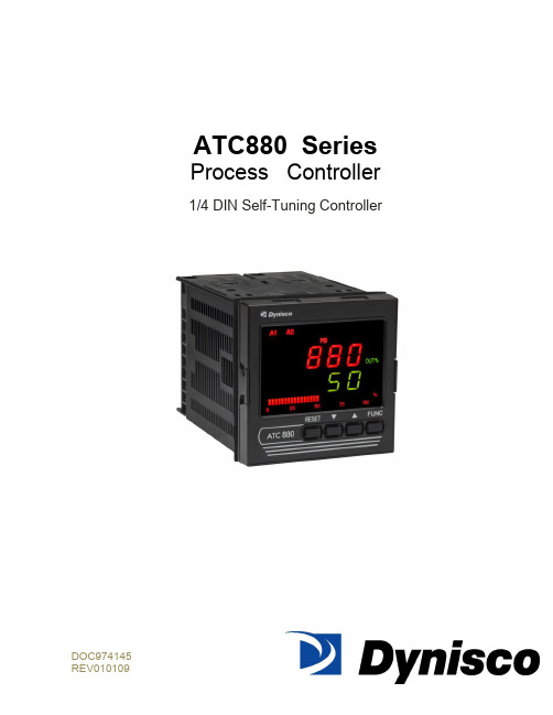
ATC880 SeriesProcess Controller1/4 DIN Self-Tuning ControllerDOC974145TABLE OF CONTENTSQUICK START INSTRUCTIONS (5)1.0 INTRODUCTION (8)2.0 SPECIFICATIONS (9)2.1 Mechanical Specifications (9)2.2 Main Power Supply & Environmental Specification (9)2.3 Display Specification (10)2.4 Primary Input Specification (11)2.5 Secondary Input (12)2.6 Pressure & Remote Set Point Inputs Common (13)2.7 Digital Input (14)2.8 Alarms (14)2.9 Optional Serial Communication Interface Specification (15)2.10 Control Output Specification (15)2.11 Retransmission Output Specification (16)2.12 Control and Retransmission Outputs Common Specification (16)2.13 Control Algorithm Specification (16)2.14 Opto-isolated Digital Input Specification (18)3.0 UNPACKING & DIMENSIONAL INFORMATION (19)3.1 Unpacking (19)3.2 Dimensional Information (19)3.3 Block Diagram (19)4.0 MOUNTING AND WIRING (21)4.1 Terminal Assignments and ratings (24)4.2 Terminal Cross Reference With Former Dynisco Model ATC770 (26)5.0 START-UP PROCEDURE (28)5.1 Configuration (28)5.2 Parameters (28)5.2.1 Getting Ready: (28)5.2.2 Keyboard Description: (28)5.2.3 Operating Mode Description: (30)5.3 Setting the Instrument‘s Basic Configuration (30)5.3.1 Setting the Shunt Calibration: (31)5.3.3 Setting the Logic Input Status (optional) (31)5.3.4 Setting the Status of Auto/Manual Selection (optional) (31)5.3.6 Setting the Line Frequency (32)5.3.7 Setting the Display Filter (32)5.4 Setting the Remote Set Point Input/Seconday Input (Optional) (33)5.4.1 Setting the Remote Set Point/Secondary Input Voltage or Current (33)5.4.2 Setting the Remote Set Point (RSP) Input Failsafe Mode (33)5.4.3 Setting the Remote Set Point Limits (33)5.4.4 Setting the Local Remote Set Point Selection (34)6.0 CONFIGURATION (35)6.1 Primary Input Setup (35)6.1.1 Setting the Primary Input Type for a Strain Gage Transducer (35)6.1.2 Setting the Shunt Calibration for Strain Gage Transducers and Amplified Transmitters (35)6.1.3 Setting the Primary Input Type for an Amplified Transmitter (35)6.1.4 Setting the Primary Input Full-Scale Value (36)6.1.5 Setting the Primary Input Low-Scale Value (36)6.1.6 Setting the Primary Input Decimal Place (37)6.1.7 Setting the Primary Input Failsafe Mode (37)6.2 Setting the Alarms: (37)6.2.1 Setting What the Alarm will Monitor (Alarm Input Channel Link): (38)6.2.2 Setting Alarm Type: (38)6.2.3 Setting the Filtering for Alarms: (38)6.2.4 Setting the Hysteresis for Alarms: (39)6.2.5 Setting the Reset Mode for Alarms: (39)6.2.6 Setting the Failsafe Mode for Alarms: (39)6.2.7 Setting the Alarms Threshold Values: (40)6.2.8 Setting the Alarms Mask Reset Type: (40)6.3 Retransmission Output Setup (40)6.3.1 Selection of the Retransmission Output (40)6.3.2 Setting the Retransmission Output Range (40)6.3.3 Setting the Retransmission Output Range High (41)6.3.4 Setting the Retransmission Output Filter (41)6.4 Setting the Control Output: (41)6.4.1 Setting the Control Output Voltage or Current: (41)6.4.2 Making the Control Output Direct/Reverse Selection: (41)6.4.3 Setting the Control Output Limit: (42)6.4.4 Setting the Control Output Manual Mode Indication: (42)6.4.5 Setting the Control Output Display: (42)6.5 Setting the Security Codes: (43)6.5.1 Setting the Security Code for Level A (43)6.5.2 Setting the Security Code for Level B (43)6.5.3 Setting the Security Code for Level C (43)6.6 Configure by Remote PC (Configuration Port Interface or CPI) (44)6.7 Configure Differential Control (45)7.0 OPERATION (51)7.1 Primary Input Calibration (51)7.1.1 Calibration of Pressure Transducers with Internal Shunt Resistor (51)7.1.2 Calibration of Amplified Pressure Transmitters with Internal Shunt Resistor (51)7.1.3 Calibration of Pressure Transducers equipped with External Shunt Resistors (51)7.1.4 Calibration of Analog Inputs Using a Pressure Calibration Source (52)7.1.5 Calibration of the ATC880 to Calibrated Linear Analog Input (52)7.2 Start-Up and Engaging SMART (53)7.2.1 Setting the Process Set Point (53)7.2.2 Engaging SMART (53)7.2.3 Engaging Automatic Control (53)7.3 The Tuning Mode (53)7.3.1 Selecting the Type of Control (54)7.3.2 Engaging the Tuning Algorithm (ATC880 in Manual Mode) (54)7.3.3 Viewing the Tuning Algorithm Parameters (54)7.3.4 Engaging the Adaptive Tuning Algorithm (ATC880 in Automatic Mode) (56)7.3.5 Automatic Stand-By in the event of a Process Upset (56)7.3.6 Automatic or Manual Start-Up (57)7.3.7 Manual/Automatic Transfer (57)7.3.8 Tuned Parameters, After SMART ―tuning‖ (58)8.0 INSTRUMENT CALIBRATION (60)8.1 General Calibration Procedure (60)8.2 RS-485 (Optional) (62)8.2.1 Serial Communication Interface Address (62)8.2.2 Protocol Type (62)8.2.3 Communication Type (62)8.2.4 Communication Baud Rate (62)8.2.5 Setting the Status of Auto/Manual Selection (optional) (63)9.0 ERROR CODES (64)9.1 Error Codes and Troubleshooting (64)9.2 ―OPEN‖ Error Code and Troubleshooting (66)9.3 Instrument Maintenance (66)10.0 NORMATIVE REFERENCES (67)11.0 PARAMETER GROUP MENUS (69)11.1 Group 1 Parameters (71)11.2 Group 2 Parameters (73)11.3 Group 3 Parameters (78)11.4 Group 4 Parameters (82)11.5 Group 5 Parameters (87)11.6 Group 6 Parameters (89)11.7 Group 9 Parameters (90)12.0 PID CONTROLLER DEFINITIONS (92)13.0 WARRANTY AND SERVICE (94)QUICK START INSTRUCTIONSMountingPrepare panel cutout to dimensions shown below (1A).If more instruments are mounted in the same panel near together, maintainthe distances between one instrumento to another like as in the figure.Slide the rubber gasket (1) over the case.Slide the instrument case into the cutout (2,1A).Attach the panel mounting hardware tightening the threaded rod (3) for asecure fit and with a screwdriver, turn the screws with a torque between 0.3and 0.4 Nm.WiringRefer to Section 4 for wiring/connections and terminal diagramConnect the wires from transducer cable as shown in the terminal diagram,turn the screws with a torque between 1.0 and 1.2 Nm..Connect final control device.Connect alarm(s) if applicable. Note that alarm defaults are High, ReverseActing for alarms 2 & 3 –alarm 1 is low inhibited.Connect power to the appropriate terminals as shown.1AScalingApply power to the instrument; Upper display will give a reading near zero.Lower display will read the manual output %.Press key until the Upper display reads NONE and lower display readsGROUP.If your transducer is not a 10,000-psi model, select GROUP3 using the Uparrow, enter with function key.Lower display reads PI.FSV (Full Scale Value), and the upper display reads10,000. Note: If your transducer is a 10,000-psi model skip next two steps.Scroll to GROUP and select 2.Using the Down arrow key set the appropriate Full Scale Value for yourtransducer.Enter using the key to scroll until GROUP legend appears again.Using Up arrow key, select GROUP2. Enter with key.Follow instructions for Calibration and Operation in Step 4 of Quick Start Calibration and OperationLower display reads ZERO.C and upper display reads OFF. Be suretransducer is at operation temperature and that no pressure is applied.Change upper display to ON by using the Up arrow key. Enter with the key. After a few seconds, the lower display will show SPAN.C and upper display will show OFF.Change upper display to ON using Up arrow key. Enter with thekey. In a few seconds lower display shows SMART and upper display showsOFF. Calibration is complete.Using the key, scroll to the GROUP display. Enter 1 with the Uparrow, and enter with the key. Instrument shows 0 on upper displayand SP on lower display.Set Process Set point. Press twice.Set Alarm 1, 2, 3 thresholds (if applicable) by pressing . Changethreshold with the up and down keys.Press twice. Lower display will read GROUP, and upper display willread none.Press key. Upper display will read 0 +/- 10 process pressure, lowerdisplay will read 0. This is control output %.Be sure process is at operating temperature.Utilizing up and down keys, manipulate the output % until the upperdisplay is reading at approximately the set point.Press key until lower display reads GROUP. Select group 2.Press key three times. Lower display reads SMART and upper displayreads OFF.Using up arrow key, turn SMART function to on. Enter with key.SMART LED will flash and a countdown will begin as the controller arrives atinitial P&I (D) parameters.Return to GROUP none and observe that the value in the upper display is theactual set point you wish to control.When the SMART LED has stopped flashing, press and hold the A/M key forat least 5 seconds. The manual LED will extinguish, and you will be inautomatic control mode.Again, return to GROUP2 and select SMART. Turn the function on with theup arrow, and enter with the . This will activate the Adaptive Tune algorithm, and will maintain the correct P&I (D) parameters for the process. Itwill remain on until manually turned off. It will also come on anytime theATC880 is the automatic control mode.Return to GROUP,None, and observe the process. The set point may beadjusted in GROUP1 while the controller is in automatic mode.Operator may alternately display Output %, Set Point, Deviation, Peak Value,or RPM by pressing the up arrow key.The preceding Quick Start instructions are the basic settings required to install, wire, and get the controller operating. Please refer to the complete installation and operation manual for additional functions. Questions on your transducer will be addressed in the manual included with your transducer.References to Profibus features and instructions should be ignored. Profibus is being considered for a future line expansion and has been accommodated in the current design.1.0 INTRODUCTIONThe ATC880 Pressure/Process Controller is a microprocessor-based instrument with the capability of controlling an extruder or other process using an advanced proprietary SMART self-tuning algor ithm. The input is user configurable to be 350Ω Strain Gage, high-level voltage or high level current. The voltage or current inputs are compatible with many process transmitter combinations. Three fully programmable alarms and an analog retransmission output are also included as part of the standard ATC880 package.Five groups of configuration parameters are available from the keyboard, and are protected by three levels of user definable software locks. (A sixth group of read-only parameters can also be viewed) In the programming mode the lower display will show the parameter being displayed, and the upper display will show its value. In the operating mode, the upper display will show the process variable, and the lower display offers the choice of displaying set point, deviation from set point, output %, RPM or peak. In addition, a red LED bar graph presents an analog representation of the main input (process variable), as well as indication of the alarm set points. The alarms are shown relative to the span of process and are indicated as missing or present bars relative to the process input.References to Profibus features and instructions should be ignored. Profibus is being considered for a future line expansion and has been accommodated in the current design.WARNING NOTE: The user should be aware that if this equipment is used in a manner not consistent with the specifications and instructions in this manual, the protection provided by the equipment might be impaired.Product Codes (ordering options)Note: UL pending only for Power Code Voltage equal to 5 (24Vac/dc, switching)2.0 SPECIFICATIONS2.1 Mechanical SpecificationsCase: Polycarbonate Black color Self-extinguishing degree V0 according to UL 94Front Panel: Designed and verified for IP65 and NEMA 4X for indoor location Installation: Panel mountingRear Terminal Block: 46 screw terminals with rear safety cover2.2 Main Power Supply & Environmental SpecificationMain Power Supply: From 100 to 240Vac (-15% to 10%), 50/60Hz switching. Option: 24Vac/dcPower supply variation: From -15% to 10% (for 100 to 240Vac). From 14 to 32 Vac/dc (for optional 24Vac/dc).Power Consumption: Max 22VA at 50Hz or Max 27VA at 60Hz for Main Power Supply from 100 to 240 VacInsulation Resistance: 100MΩ @500VdcDielectric Strength: 1500V rms for 1 min, 1800V for 1 sec.Ambient Temperature: From 0 to 50°C. Ensure the enclosure provides adequate ventilationStorage Temperature: From -20 to 70°CHumidity: Max 85% RH non-condensingAltitude: This product is not suitable for use above 2000m (6562ft) or in explosive or corrosive atmospheresWatchdog: Hw/Sw is provided for automatic restartAgency Approvals: UL File # 193253Self-Certification: CEElectromagnetic Compatibility:The instrument is compliant with the European Directive 2004/108/CE according to Product Standard EN 61326-1.Emission limit:class A – group 1 ISM for equipment suitable for use in allestablishments other then domestic and those directly connected to a lowvoltage power supply network which supplies buildings used for domesticpurposes.Immunity:Electrostatic discharge (according to EN 61000-4-2):contact discharge = 4kV; air discharge = 8kVRadio-frequency electrical magnetic (according to EN 61000-4-3):EM field (amplit. mod.) = 10 V/m (80MHz to 1 GHz);3V/m (1,4 GHz to 2 GHz);1 V/m (2 GHz to 2,7 GHz)Electrical fast transient/burst (according to EN 61000-4-4):AC Power = 2kV;I/O Signal/Control = 2kV (5/50 ns, 5 kHz);I/O Signal/Control connected directly to mains supply = 2kV (5/50 ns, 5kHz)Surge (according to EN 61000-4-5):AC power = 1kV (Line to Line) / 2kV (Line to GND);I/O Signal/Control = 1kV (Line to Line) / 2kV (Line to GND)Radio frequency common mode (according to EN 61000-4-6):AC Power = 3 V (150kHz to 80 MHz);I/O Signal/Control = 3 V (150kHz to 80 MHz)Voltage dips/short interruptions (according to EN 61000-4-11):0% during 1 cycle; 40% during 12 cycles; 70% during 30 cyclesThis equipment is intendent for use in an industrial location. There may be potential difficulties ensuring electromagnetic compatibility in other environmental due to conducted as well as radiated disturbances.Safety Requirements:The instrument is compliant with the European Directive 2006/95/CE according to Reference Standard EN 61010-1 for installation category I and pollution degree 2 Installation category CAT I: Voltage transients on any power connected tothe instrument must not exceed 1.5kV. Pollution degree 2: Conductive pollution must be excluded from thecabinet in which the instrument is mounted.2.3 Display SpecificationDisplay: LED technology, custom type.Upper Digits: Red color, 5 numeric digits, 7 segments with decimal point 13.2mm high. Lower Digits: Green color, 5 alphanumeric digits (British flag), 14 segments with decimal points, 11.3 mm high.Bar Graph: Red color, 35 segment with 3% resolution. Displays continuous bar graph to indicate the measured variable of the main input (0-100% full scale). Alarm set point values displayed. Last segment blinks for pressure greater than full scale value. Indicators (Beacons):Red LED‘s annunciations:A1: Lit when alarm 1 is in alarm stateA2: Lit when alarm 2 is in alarm stateA3: Lit when alarm 3 is in alarm stateREM: Lit when device is controlled by serial link0-25-50-75-100-%: These six LEDs are always on to improve the bar graphindication.SMRT: Flashing when the first step of SMART algorithm is activated. Lit whenthe second step of SMART algorithm is activatedMAN: Lit when device is in manual modeRSP: Lit when Remote Set Point is selectedKg/cm2, PSI, Bar, MPa: Engineering unit for the pressure input. These fourbeacons are located within the display window, between the numeric digits andthe alarm beacons.Green LED‘s ann unciations:SP: Lit when lower display shows the Set PointPEAK: Lit when lower display shows the peak valueDEV: Lit when lower display shows the deviation (Measured Variable minus SetPoint)OUT%: Lit when lower display shows the Output Value (absolute value with 0.1% resolution)RPM: Lit when lower display shows the Output Value scaled to RPM2.4 Primary Input SpecificationMain Input: Selectable between strain gage and linear by software configuration.Strain Gage Input: From 340 to 5000Ω, 1-4 mV/V. Excitation 10V +/- 7%. 5 wires connection.Linear Input: Selectable between 0-5Vdc, 0-10Vdc, 0-20mA, 4-20mA.Input Signal: -25/125% of full scale (approximately –10 / 50mV).Shunt Calibration: With or without shunt resistor (value programmable from 40.0 to100.0%).Zero Balance: ±25% of full scale (approximately ± 10 mV).Auxiliary Power Supply: 24Vdc / 1.5W power supply for two or four wire transmitter. Input Impedance: <10Ω for linear current input;>165KΩ for linear voltage inputInput Protection: Open circuit detection for strain gage (on signal and excitation wires) and 4-20mA inputs; it is not available for 0-5Vdc, 0-10Vdc and 0-20mA. Up or down scale keyboard programmable.Sampling time: 50mS typical.Display Update Time: Selectable: 50, 100, 250 or 400mS.Engineering Units: Dedicated beacons within the display window.Calibration Mode: Field calibrations (zero and span) are applicable for both strain gage and linear input. Moreover it is possible to delete the field calibration done by the end user and to restore original factory calibration values.Input resolution: 4000 counts.Full scale value Resolution10/4000 1 count4002/8000 2 counts8005/20000 5 counts20010/40000 10 counts40020/80000 20 counts80050/99950 50 countsDecimal Point: Settable in any position of the display or none at all.2.5 Secondary InputSecondary input: Selectable among 0-5Vdc, 0-10Vdc, 0-20mA, 4-20mA or strain gage (optional).Function: Second sensor for the measurement of a differential pressure (in case of strain gage or linear input); remote set point (only linear inpu).Input Protection: Open circuit detection for strain gage (on signal and excitation wires) and 4-20mA inputs; not available for 0-10Vdc, 0-5Vdc and 0-20mA inputs. Up or down scale keyboard.Input Impedance:< 10Ω for linear current input> 165KΩSampling Time: Remote set point input is selectable among 100, 200, 500 or 1000mSe; differential pressure is 50 mS, typical.Display update: At each sample.Input Resolution with Linear Input: 4000 counts.Low/High Scale Values: Secondary input of a differential pressure: freely settable, but with the same resolution and decimal point position of the primary pressure input. Remote set point: settable from 0 to pressure input full scale value with the same resolution and decimal point position of pressure input.NOTE: This input is not isolated from main input. A double or reinforced insulation between instrument output and power supply must be guaranteed by the external device.2.6 Pressure & Remote Set Point Inputs CommonCommon Mode Rejection Ratio: >120dB @50/60HzNormal Mode Rejection Ratio: >60dB @ 50/60HzStrain gage input: From 340 to 5000Ω, 1-4 mV/V. Excitation 10V +/- 7%. 5 wires connection.Input signal: -25/125% of full scale (approximately -10/50mV).Shunt calibration: With or without shunt resistor (value programmable from 40.0 to 100.0%), the same setting will be used for both inputs (main and secondary) when the differential pressure measurement is selected.Zero balance: +/- 25% of full scale (approximately +/- 10mV).Reference accuracy: +/- 0.1% FSV +/-1 digit @ 25 +/- 1°C and nominal power supply voltage.Operative accuracy: temperature drift: < 300 ppm/K of full span for current, voltage and strain gage input.Zero and span calibration: If differential input used, there is no relation between the calibration of the two single sensors; each input is provided with its own zero and span calibration parameters.2.7 Digital InputDigital input: One input from contact closure (voltage free). It is marked as ―Reset‖ on rear panel, contacts 23 and 24. It may be keyboard programmable for the following functions:• alarm reset• peak reset• alarm and peak reset• zero calibration of the primary input• zero calibration of the primary input, alarm and peak resetNOTE: This input is not isolated from main input. A double or reinforced insulation between instrument output and power supply must be guaranteed by the external device.Opto-isolated Digital Input: Four optional digital inputs are provided for control purposes. The interface circuit is opto-isolated with respect to the CPU and analog inputs.DIG1: This contact acts as an automatic / manual switch, if it is enabled by the proper parameter (closed means manual mode, open means automatic mode).DIG2: Control output value increaseDIG3: Control output value decreaseThese two contacts are used to increase / decrease the output value with a linear, not exponential, rate of change (about 20 seconds for a full scale variation from 0 to 100%). DIG4: This contact is used to switch the controller from automatic to manual mode setting to zero the control output. When this logic input is closed the transfer from manual to automatic mode by the front panel is inhibited while the user may modify the control output. To return to automatic mode the logic input should be de-activated.2.8 AlarmsAlarm Outputs: 3 standard alarms (AL1, AL2 and AL3).AL1 and AL2 Contacts: 1 SPDT 2A max @ 240Vac resistive load.AL3 Contacts: 1 SPST 2A max @ 240Vac resistive load.Contact Protection: Varistor for spike protection.Alarm Type: Each alarm is keyboard programmable for:• Process / Deviation / Band• High / Low / Low inhibited on start up• Auto / Manual resetAlarm Mask: The alarm mask may be restored using the keyboard parameter (AL.MSK). Moreover the alarm mask of deviation and band alarms is restored at set point change and during set point ramp.Excitation Type: Keyboard configurable for each alarm: relay coil energized in no alarm condition (failsafe) or relay coil energized in alarm condition (non-failsafe). The default condition is failsafe.Threshold: From 0 to 110% Full Scale (the threshold may be limited due to the selected full scale value).Hysteresis: Keyboard programmable for each alarm; from 0.1% to 10.0% of span or 1 Least Significant Digit (whichever is greater) for each alarm.Alarm Filter: Selectable from the following values: OFF, 0.4S, 1S, 2S, 3S, 4S, 5S.Alarm Update Time: At every input conversion.2.9 Optional Serial Communication Interface SpecificationSerial Interface: RS-485 type. Opto-isolated.Protocol Type: Modbus/Jbus (RTU mode).Type of Parameters: Run-time and configuration are available by serial link.Device Address: From 1 to 255NOTE: The physical interface can only support up to 31 devices for each segment.Use multiple segments for more than 31 devices.Baud Rate: 600 up to 19200 baud.Format: 1 start bit, 8 bits with or without parity, 1 stop bitParity: Even/Odd.2.10 Control Output SpecificationControl Output: Opto-isolated from CPU input and output circuits.Type of Analog Output: Keyboard selectable between:•+ 0/10Vdc min load 5KΩ•– 10/+10 VDC min load 5KΩ•+ 0/5Vdc min load 5KΩ•+ 0/20mA max load 500KΩ•– 4/20mA max load 500ΩResolution: 0.1% in manual mode, 0.03% in automatic mode.Scaling: The output control value may be displayed in two modes:• from 0.0 to 100.0% (0.1% resolution)• from a low to a high limit selection from -10000 to 100002.11 Retransmission Output SpecificationRetransmission Output: Opto-isolated from CPU input and output circuits.Type of Analog Output: Keyboard selectable between:•+ 0/10Vdc min load 5KΩ, with under/overrange capability from -2.5 to 12.5V.•± 10Vdc min load 5KΩ, with under/overrange capability from -12.25 to 12.5V.•+ 0/5Vdc min load 5KΩ, with under/overrange capability from -1.25 to 6.25V.•+ 0/20mA max load 500Ω, with un der/overrange capability from 0 to 24mA (max. load 400Ω over 20 mA).• + 4/20mA max load 500Ω, with under/overrange capability from 0 to 24mA (max. load 400Ω over 20mA).Resolution: 0.1% of output modeScaling: The retransmission low and high limits are selectable from 0 to full scale input value. The two scaling values may be freely selectable within the above range. This allows for a direct or reverse output type.Output Filter: Selectable from the following values: OFF, 0.4S, 1S, 2S, 3S, 4S, 5S2.12 Control and Retransmission Outputs Common SpecificationReference Accuracy: ±0.1% of output span @ 25 ± 10°C and nominal line voltage. Linearity Error: <0.1% of output span.Output Noise: <0.1% of output span.2.13 Control Algorithm SpecificationControl Type: PID plus Integral Preload plus Anti-Reset WindupOutput Value Indication: Selectable between the following Modes:• Range 0/100.0%• Selectable with two calibrated values for RPM indication• In automatic mode either mode is available• In manual mode, a parameter is provided to select the first or second method of indication.SMART Algorithm: The SMART procedure is activated by setting the SMART Parameter to ON. In manual mode the controller will start the TUNE algorithm (SMRT led flashes), while in automatic mode it will enable the ADAPTIVE function (SMRT led lights steady).The SMART can select two types of procedures:1. The TUNE algorithm2. The Adaptive algorithmTUNE ALGORITHMTo implement the TUNE algorithm, set the instrument in manual mode and the select SMART ON. SMART will switch to OFF after the PID parameters (PB, TI, TD) are calculated (during this procedure the LED will be flashing). The basic concepts of the auto-tuning system are based on the open loop step response, for this reason the TUNE function may be activated only in the manual mode.The equivalent mathematical model of the process is characterized by three parameters: the gain, the time constant and the equivalent time delay. The power output of the controller is changed by a small step value. Then, the controller stores the process variable response. From the transient response, the controller estimates the three basic process parameters by means of the area‘s method. It applies these parameters, and re-runs the step process. When this is done, it calculates the final PID parameters.The step response is a convenient way to characterize this type of process dynamics because its model is based on the alteration of the behavior of the process and very accurately determining the response. It is capable of estimating the process parameters with high precision.ADAPTIVE ALGORITHMIn order to implement the adaptive algorithm, the instrument should be in automatic mode. Then change SMART to ON. In this case the ON will be remembered by the instrument even if the instrument was switched off.In order to deactivate the adaptive processes, return the SMART parameter to OFF. The ADAPTIVE is an on-line algorithm that ―observes‖ the measured value and l ooks for oscillation due to a variation of the load or the set point. When a significant pattern is―recognized,‖ the decision procedure starts to recalculate the PID parameters of the controller. While the ADAPTIVE procedure is enabled the PID parameters can only be monitored.AUTOMATIC STAND-BY: This function avoids overshoot due to temporary process。
欧洲品牌Preventa的XPSUS12AP安全自动化模块产品说明书

Product datasheetCharacteristicsXPSUS12APPreventa module Cat.4 features 2*XPSUAF +enabling movement 24vac/dc screwMainRange of productPreventa Safety automation Product or component type Preventa safety module Safety module name XPSUSSafety module applicationFor electrical monitoring of two-hand control stations Monitoring antivalent contactsFor emergency stop, guard and light curtain monitoring Function of moduleEmergency stop button with 2 NC contacts Guard monitoring with 1 or 2 limit switches Monitoring 2 PNP sensors Magnetic switch monitoring Light curtain monitoring RFID switchMonitoring of electro-sensitive protection equipment (ESPE)Safety levelCan reach PL e/category 4 conforming to ISO 13849-1Can reach SILCL 3 conforming to IEC 62061Can reach SIL 3 conforming to IEC 61508Safety reliability dataMTTFd > 30 years conforming to ISO 13849-1Dcavg >= 99 % conforming to ISO 13849-1PFHd = 1.13E-09 conforming to ISO 13849-1HFT = 1 conforming to IEC 62061PFHd = 1.13E-09 conforming to IEC 62061SFF > 99% conforming to IEC 62061HFT = 1 conforming to IEC 61508-1PFHd = 1.13E-09 conforming to IEC 61508-1SFF > 99% conforming to IEC 61508-1Type = B conforming to IEC 61508-1Electrical circuit typeNC pair PNP pairAntivalent pair OSSD pairConnections - terminalsRemovable screw terminal block, 0.2...2.5 mm² solid or flexibleRemovable screw terminal block, 0.25...2.5 mm² flexible with ferrule single conductor Removable screw terminal block, 0.2...1.5 mm² solid or flexible twin conductorRemovable screw terminal block, 2 x 0.25...1 mm² flexible with ferrule without cable end, with bezel Removable screw terminal block, 2 x 0.5...1.5 mm² flexible with ferrule with cable end, with bezel [Us] rated supply voltage24 V AC - 15...10 %i s c l a i m e r : T h i s d o c u m e n t a t i o n i s n o t i n t e n d e d a s a s u b s t i t u t e f o r a n d i s n o t t o b e u s e d f o r d e t e r m i n i n g s u i t a b i l i t y o r r e l i a b i l i t y o f t h e s e p r o d u c t s f o r s p e c i f i c u s e r a p p l i c a t i o n s24 V DC - 20...20 %ComplementarySynchronisation time between inputs0.5 s2 s4 sType of start Automatic/manual/monitoredPower consumption in W2 W 24 V DCPower consumption in VA 5.0 VA 24 V AC 50/60 HzInput protection type Internal, electronicSafety outputs 2 NOSafety inputs 2 safety input 24 V DC 5 mAMaximum line resistance60 OhmInput compatibility Normally closed circuit conforming to ISO 14119XC limit switch conforming to ISO 14119Mechanical contact conforming to ISO 14119Normally closed circuit conforming to ISO 13850Antivalent pair conforming to ISO 14119OSSD pair conforming to IEC 61496-1-2Two-hand control conforming to EN 574/ISO 13851-III A3-wire proximity sensors PNPOutput type Relay output : 250 V AC, AC-1, B300 for normally open relay contactRelay output : 250 V AC, AC-15, D300 for normally closed relay contactRelay output : 24 V DC, DC-1, R300 for normally open relay contactRelay output : 24 V DC, DC-13, R300 for normally closed relay contact[Ie] rated operational current5 A AC-1 for normally open relay contact3 A AC-15 for normally open relay contact5 A DC-1 for normally open relay contact3 A DC-13 for normally open relay contact3 A AC-1 for normally closed relay contact1 A AC-15 for normally closed relay contact3 A DC-1 for normally closed relay contact1 A DC-13 for normally closed relay contactControl outputs 3 on/off configurable pulsed outputInput/Output type Semiconductor pulsed diagnostic output 24 V DC, 20 mA Z1, not safety-related8 A[Ith] conventional free air thermalcurrentAssociated fuse rating10 A gG for NO relay output circuit conforming to IEC 60947-1Minimum output current10 mA for relay outputMinimum output voltage12 V for relay output20 msMaximum response time on inputopen[Ui] rated insulation voltage250 V (pollution degree 2) conforming to EN/IEC 60947-1[Uimp] rated impulse withstand voltage4 kV overvoltage category II conforming to EN/IEC 60947-1Local signalling LED (green)power ON:LED (red)error:LED (yellow)safety output status:LED (yellow)start input:LED (yellow)safety input S12:LED (yellow)safety input S13:LED (yellow)safety input S22:LED (yellow)safety input S23:Mounting support35 mm symmetrical DIN railDepth120 mmHeight100 mmWidth22.5 mmProduct weight0.200 kgEnvironmentStandards IEC 60947-5-1IEC 61508-1 functional safety standardIEC 61508-2 functional safety standardIEC 61508-3 functional safety standardIEC 61508-4 functional safety standardIEC 61508-5 functional safety standardIEC 61508-6 functional safety standardIEC 61508-7 functional safety standardISO 13849-1 functional safety standardIEC 62061 functional safety standardProduct certifications TÜVCULusIP degree of protection IP20 (terminals) conforming to EN/IEC 60529IP40 (housing) conforming to EN/IEC 60529IP54 (mounting area) conforming to EN/IEC 60529Ambient air temperature for storage-25…85 °CRelative humidity5…95 % non-condensingOffer SustainabilitySustainable offer status Green Premium productEU RoHS Directive Pro-active compliance (Product out of EU RoHS legal scope)EU RoHS DeclarationMercury free YesRoHS exemption information YesChina RoHS Regulation China RoHS declarationEnvironmental Disclosure Product Environmental ProfileCircularity Profile End of Life InformationWEEE The product must be disposed on European Union markets following specific waste collection andnever end up in rubbish binsContractual warrantyWarranty18 monthsDimensions DrawingsDimensionsFront and Side Views(A) :Product drawing(B) :Screw clamp terminal(C) :Side view(1) :Removable terminal blocks, top(2) :Removable terminal blocks, bottom(3) :LED indicators(4) :Start function selector(5) :Function selector(6) :Connector for optional output extension module (lateral)(7) :Sealable transparent coverMounting to DIN railScrew-mountingConnections and SchemaWiring Drawing(1) :A1-A2 (Power supply)(2) :S11-S12-S13-S21-S22-S23 (Single-channel safety input)(3) :Y1-Y2 (Start)Output13-23-14-24 :EXT :Connector for optional extension moduleB2 :Common ground terminalZ1 :Pulsed output for diagnostics, not safety-related。
- 1、下载文档前请自行甄别文档内容的完整性,平台不提供额外的编辑、内容补充、找答案等附加服务。
- 2、"仅部分预览"的文档,不可在线预览部分如存在完整性等问题,可反馈申请退款(可完整预览的文档不适用该条件!)。
- 3、如文档侵犯您的权益,请联系客服反馈,我们会尽快为您处理(人工客服工作时间:9:00-18:30)。
(2), le boîtier (14) étant en outre configuré pour être relié à un disjoncteur côté basse tension, BT, et à un disjoncteur côté HT, le module de sécurité (3) étant configuré pour déclencher les disjoncteurs côté BT et HT en fonction de la détection d’anomalie, le module de sécurité (3) étant configuré pour être alimenté par une alimentation indépendante.
mateur mais pas le secondaire (côté BT) du transforma-
particulier sur un module de sécurité pour un transfor- 5 teur, de telle sorte que le transformateur en défaillance
(30) Priorité: 29.03.2018 FR 1852773
(71) Demandeur: P
(72) Inventeur: Lefevre, Gilles 76530 Grand Couronne (FR)
(74) Mandataire: Fidal Innovation 4-6 avenue d’Alsace 92400 Courbevoie (FR)
(22) Date de dépôt: 28.03.2019
(51) Int Cl.: H02H 5/06 (2006.01) H02H 5/08 (2006.01)
H01F 27/40 (2006.01) H02H 7/04 (2006.01)
(84) Etats contractants désignés: AL AT BE BG CH CY CZ DE DK EE ES FI FR GB GR HR HU IE IS IT LI LT LU LV MC MK MT NL NO PL PT RO RS SE SI SK SM TR Etats d’extension désignés: BA ME Etats de validation désignés: KH MA MD TN
(54) MODULE DE SECURITE POUR TRANSFORMATEUR DE PUISSANCE HAUTE TENSION, ENSEMBLE DE SUPERVISION ET TRANSFORMATEUR DE PUISSANCE HAUTE TENSION ASSOCIE
(57) L’invention a pour objet un module de sécurité (3) pour un transformateur de puissance haute tension, HT, (1) équipé d’un module de détection d’anomalie (2), le module de sécurité (3) comprenant un boîtier (14) configuré pour être relié au module de détection d’anomalie (2), le boîtier (14) comprenant un moyen d’indication d’anomalie configuré pour indiquer au moins une anomalie signalée par le module de détection d’anomalie
mateur de puissance haute tension, sur un ensemble de
n’est pas complètement isolé du réseau. De plus, aucune
supervision comprenant un tel module de sécurité et sur
[0001] La présente invention concerne le domaine des
coupent uniquement le primaire (côté HT) du transfor-
transformateurs de puissance haute tension, et porte en
sécurité n’empêche la remise en fonctionnement de la
un transformateur de puissance haute tension associé.
cellule de disjoncteur HT du transformateur lorsque l’ano-
EP 3 547 475 A1
Printed by Jouve, 75001 PARIS (FR)
1
EP 3 547 475 A1
2
Description
NF C17-300 des conditions d’utilisation des diélectriques
liquides. En effet, les modules de protection existants
[0002] Les transformateurs de puissance sont des
(19)
TEPZZ¥547475A_T
(11)
EP 3 547 475 A1
(12)
DEMANDE DE BREVET EUROPEEN
(43) Date de publication: 02.10.2019 Bulletin 2019/40
(21) Numéro de dépôt: 19315018.2