数据通信与网络课后习题答案上
数据网络课后习题答案
1第一章习题解答1.1什么是计算机网络什么是计算机网络什么是计算机网络什么是计算机网络?答:我们可以把计算机网络定义为:把分布在不同地点且具有独立功能的多个计算机,通过通信设备和线路连接起来,在功能完善的网络软件运行下,以实现网络中资源共享为目标的系统。
1.2试分析阐述计算机网络与分布式系统的异同点。
答:计算机网络是把分布在不同地点且具有独立功能的多个计算机,通过通信设备和线路连接起来,实现资源的共享;分布式系统是在分布式计算机操作系统或应用系统的支持下进行分布式数据处理和各计算机之间的并行工作,分布式系统在计算机网络基础上为用户提供了透明的集成应用环境。
所以,分布式系统和计算机网络之间的区别主要在软件系统。
1.8什么是网络协议?由哪几个基本要素组成?答:简单地说,协议是指通信双方必须遵循的、控制信息交换的规则的集合,是一套语义和语法规则,用来规定有关功能部件在通信过程中的操作,它定义了数据发送和接收工作中必经的过程。
协议规定了网络中使用的格式、定时方式、顺序和检错。
一般说,一个网络协议主要由语法、语义和同步三个要素组成。
语法:指数据与控制信息的结构或格式,确定通信时采用的数据格式,编码及信号电平等。
即对所表达内容的数据结构形式的一种规定,也即"怎么讲".例如,在传输一份数据报文时数据格式,传输一封信函的地址格式等。
语义:协议的语义是指对构成协议的协议元素含义的解释,也即"讲什么".不同类型的协议元素规定了通信双方所要表达的不同内容(含义).例如,在基本型数据链路控制协议中规定,协议元素SOH的语义表示所传输报文的报头开始;而协议元素ETX的语义,则表示正文结束等。
3同步:规定了事件的执行顺序.例如在双方通信时,首先由源站发送一份数据报文,如果目标站收到的是正确的报文,就应遵循协议规则,利用协议元素ACK来回答对方,以使源站知道其所发出的报文已被正确接收。
通信网络基础(李建东盛敏)课后习题答案
通信⽹络基础(李建东盛敏)课后习题答案1.1答:通信⽹络由⼦⽹和终端构成(物理传输链路和链路的汇聚点),常⽤的通信⽹络有A TM ⽹络,X.25分组数据⽹络,PSTN ,ISDN ,移动通信⽹等。
1.2答:通信链路包括接⼊链路和⽹络链路。
接⼊链路有:(1)Modem 链路,利⽤PSTN 电话线路,在⽤户和⽹络侧分别添加Modem 设备来实现数据传输,速率为300b/s和56kb/s ;(2)xDSL 链路,通过数字技术,对PSTN 端局到⽤户终端之间的⽤户线路进⾏改造⽽成的数字⽤户线DSL ,x 表⽰不同的传输⽅案;(3)ISDN ,利⽤PSTN 实现数据传输,提供两个基本信道:B 信道(64kb/s ),D 信道(16kb/s 或64kb/s );(4)数字蜂窝移动通信链路,⼗⼏kb/s ~2Mb/s ;(5)以太⽹,双绞线峰值速率10Mb/s,100Mb/s 。
⽹络链路有:(1)X.25提供48kb/s ,56kb/s 或64kb/s 的传输速率,采⽤分组交换,以虚电路形式向⽤户提供传输链路;(2)帧中继,吞吐量⼤,速率为64kb/s ,2.048Mb/s ;(3)SDH (同步数字系列),具有标准化的结构等级STM-N ;(4)光波分复⽤WDM ,在⼀根光纤中能同时传输多个波长的光信号。
1.3答:分组交换⽹中,将消息分成许多较短的,格式化的分组进⾏传输和交换,每⼀个分组由若⼲⽐特组成⼀个⽐特串,每个分组都包括⼀个附加的分组头,分组头指明该分组的⽬的节点及其它⽹络控制信息。
每个⽹络节点采⽤存储转发的⽅式来实现分组的交换。
1.4答:虚电路是分组传输中两种基本的选择路由的⽅式之⼀。
在⼀个会话过程开始时,确定⼀条源节点到⽬的节点的逻辑通路,在实际分组传输时才占⽤物理链路,⽆分组传输时不占⽤物理链路,此时物理链路可⽤于其它⽤户分组的传输。
会话过程中的所有分组都沿此逻辑通道进⾏。
⽽传统电话交换⽹PSTN 中物理链路始终存在,⽆论有⽆数据传输。
《数据与计算机通信》课后习题参考答案

《数据与计算机通信》课后习题及参考答案第2章的参考答案2.1答案:设发送消息的蓝军为A,另外一个蓝军为B。
再设步兵由一头到量外一头所用的时间为t,可以定义两军的通信协议如下:(1)A发送消息后2t时间内还灭有收到B的确认,则重发,直到收到确认。
(2)B收到消息后,立即发送去确认知道不再收到A的消息。
(3)若在中午之前t时刻,A还没有收到B的确认信息,或者B在中午前的2t时间内还继续收到A发来的消息,则第二天进攻。
2.3答案:(1)预定(A)客人(Guest)向主人(Hosts)发出要Pizza的Request。
(B)主人接受请求,提起电话拨Pizza饼店,在电话中提出预定的种类和数量。
(C)Pizza店的外卖服务生(Order Clerk)填好订单,然后传送给Pizza Cook。
完成;(2)送货(A)Pizza Cook将做好的Pizza饼给服务生;(B)服务生在订单上签字后送给送货车司机,司机开车取送货,沿道路送往订货人的地点;(C)送货车司机到达后,拿出定单和主人交接;(D)主人将送来的Pizza饼再送给客人(Guest)2.4 答案A.(1)中国总理与英文翻译之间:(a)中国总理对自己的英文翻译说中文;(b)中国翻译将中文翻译成英文后给法国总理的英文翻译;(2)法国总理与英文翻译之间(a)法国总理的英文翻译接收中国总理的英文翻译给自己的英文翻译;(b)将英文翻译成法文,然后给法国总理,反之亦然。
B.这三者之间要实现一种类似于电信系统中三方通信之类的过程:(1)中国总理拿起电话,说中文给中文/德文翻译(2)德文翻译把中文翻译成德文,然后通过电话线传送给法国总理的德文/法文翻译(3)德文/法文翻译将接收到的德文翻译成法文(4)德文/法文翻译将翻译过来的法文给法国总理听2.7 答案a.在分段情况下,都需要包含N层数据首部的拷贝b.在组合的情况下,可以用一个N层的数据首部组合成单一的N-1层PDU。
计算机网络课后习题参考答案第四章
第四章网络层1.网络层向上提供的服务有哪两种?是比较其优缺点。
网络层向运输层提供“面向连接”虚电路(Virtual Circuit)服务或“无连接”数据报服务前者预约了双方通信所需的一切网络资源。
优点是能提供服务质量的承诺。
即所传送的分组不出错、丢失、重复和失序(不按序列到达终点),也保证分组传送的时限,缺点是路由器复杂,网络成本高;后者无网络资源障碍,尽力而为,优缺点与前者互易2.网络互连有何实际意义?进行网络互连时,有哪些共同的问题需要解决?网络互联可扩大用户共享资源范围和更大的通信区域进行网络互连时,需要解决共同的问题有:不同的寻址方案不同的最大分组长度不同的网络接入机制不同的超时控制不同的差错恢复方法不同的状态报告方法不同的路由选择技术不同的用户接入控制不同的服务(面向连接服务和无连接服务)不同的管理与控制方式3.作为中间设备,转发器、网桥、路由器和网关有何区别?中间设备又称为中间系统或中继(relay)系统。
物理层中继系统:转发器(repeater)。
数据链路层中继系统:网桥或桥接器(bridge)。
网络层中继系统:路由器(router)。
网桥和路由器的混合物:桥路器(brouter)。
网络层以上的中继系统:网关(gateway)。
4.试简单说明下列协议的作用:IP、ARP、RARP和ICMP。
IP协议:实现网络互连。
使参与互连的性能各异的网络从用户看起来好像是一个统一的网络。
网际协议IP是TCP/IP体系中两个最主要的协议之一,与IP协议配套使用的还有四个协议。
ARP协议:是解决同一个局域网上的主机或路由器的IP地址和硬件地址的映射问题。
RARP:是解决同一个局域网上的主机或路由器的硬件地址和IP地址的映射问题。
ICMP:提供差错报告和询问报文,以提高IP数据交付成功的机会因特网组管理协议IGMP:用于探寻、转发本局域网内的组成员关系。
5.IP地址分为几类?各如何表示?IP地址的主要特点是什么?分为ABCDE 5类;每一类地址都由两个固定长度的字段组成,其中一个字段是网络号net-id,它标志主机(或路由器)所连接到的网络,而另一个字段则是主机号host-id,它标志该主机(或路由器)。
计算机网络(第七版)部分课后习题含答案
计算机网络(第七版)部分课后习题含答案1. 课后习题一答案:a) 网络边缘即指连接着终端设备的那一层网络,它是网络的边界部分,负责处理终端设备与网络的通信。
b) 网络核心即指网络中承载着传输数据的主干部分,它是网络的中间部分,负责路由数据、转发数据以及进行网络调度。
2. 课后习题二答案:a) 局域网(LAN)是指在较小的范围内,由某个组织或机构所拥有和控制的一组相互连接的计算机和网络设备。
它通过局限范围内的高速物理介质连接,并保证了较低的传输延迟和更高的带宽。
b) 广域网(WAN)是指覆盖较大地理范围的计算机网络,它通过公共或专用的通信链路来连接不同地域的网络。
WAN通常由多个LAN组成,并使用路由器来实现不同网络之间的数据转发。
3. 课后习题三答案:a) Huffman编码是一种变长编码方法,它根据信源符号出现的概率分布来构造编码表,使得出现概率较高的符号获得较短的编码。
这样可以有效地压缩数据,减小数据传输的带宽。
b) 奇偶校验是一种简单的错误检测方法,它通过在数据中添加一位校验位来判断数据中的错误。
奇偶校验位的值取决于数据中1的个数,使得数据的总位数为奇数或偶数。
接收方根据接收到的数据和校验位的奇偶性来判断数据是否出现错误。
4. 课后习题四答案:a) 延迟是指数据在网络中传输所需要的时间。
它包括传输延迟(发送数据所需的时间)、传播延迟(数据在传输介质中传播所需的时间)和处理延迟(数据在网络设备中处理所需的时间)。
b) 吞吐量是指网络在单位时间内能够传输的数据量。
它可以用字节/秒或位/秒来表示。
吞吐量取决于网络的带宽和网络的利用率。
5. 课后习题五答案:a) 虚拟专用网络(VPN)是利用公共网络(如互联网)来构建的一种安全的私有网络。
它通过加密和隧道技术来保护数据的安全性和隐私性,使得用户在公共网络上可以安全地访问私有网络资源。
b) 路由器是一种网络设备,用于在多个网络之间转发数据包。
它能够根据数据包中的目标地址来选择合适的路径,并进行数据转发。
计算机网络课后习题答案完整版
计算机网络课后习题答案完整版一、选择题1. B2. C3. A4. D5. B6. C7. A8. D9. B10. A二、填空题1. 分组交换2. 物理层3. 虚电路4. 数据链路层5. 网络层6. 数据包7. 传输层8. 应用层9. TCP/IP10. HTTP三、简答题1. OSI模型是开放系统互联参考模型,它是一个将计算机网络体系结构分成七个不同功能层的概念模型。
每个层在进行通信时,只需要考虑与该层相邻的上下两个层之间的通信细节,而不需要关心其他层的具体实现。
这样分层的设计旨在提高系统的可靠性、可维护性和可扩展性。
2. 物理层负责传输原始的比特流,是计算机网络的基础。
在物理层中,主要要考虑的问题是如何在传输媒介上传输比特流,并确保传输的可靠性和速度。
3. 虚电路是一种通信方式,其特点是在通信前需要建立连接,并且传输的数据包按照建立连接时分配的路由进行传输。
虚电路具有较高的可靠性和可控性,但建立连接的过程较为复杂,且传输时会有一定的延迟。
4. 数据链路层主要负责将物理层传输的比特流转化为数据帧,并进行错误检测和纠正。
数据链路层还负责对数据进行分组和重新组装,以及对数据的流量控制和传输控制。
5. 网络层负责将数据包从源主机传输到目标主机。
网络层主要要解决的问题是如何选择合适的路径,并进行数据的分组和重组。
IP协议是网络层中最重要的协议之一。
6. 传输层主要负责提供端到端的可靠通信。
传输层主要要解决的问题是如何对数据包进行序列化、分组和重组,并确保数据的可靠传输。
TCP协议是传输层中最常用的协议之一。
7. 应用层是计算机网络体系结构中最靠近用户的一层。
应用层负责处理用户的请求和提供相关的服务,例如HTTP协议用于在Web中传输超文本。
8. TCP/IP是一组用于计算机网络的协议,它是互联网的基础。
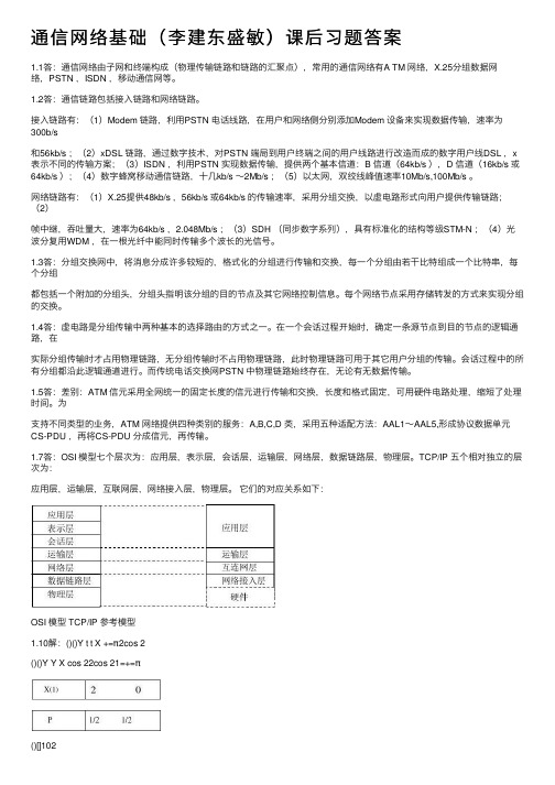
TCP/IP协议族由四个层次组成,分别是网络接口层、网络层、传输层和应用层。
9. HTTP是一种应用层协议,它是在Web中传输超文本的主要协议。
计算机网络技术基础课后习题参考答案
高等院校计算机基础教育规划教材《计算机网络技术基础》课后习题参考答案习题1参考答案一、选择题1.B2.B3.B4.A5.C二、填空题1.资源,通信2.局域网,城域网,广域网3.计算机系统数据通信系统网络软件及协议4.金税金桥金关5.服务器三、思考题1.计算机网络根据不同的分类标准可分为许多类别,如根据网络的拓扑结构分类为星型网,环型网等,根据网络交换方式分为电路交换网,分组交换网等。
在这些分类标准中,最常用的是根据网络的覆盖范围分类,这种分类方法可以很好的反映不同类型网络的技术特征。
由于网络覆盖的地理范围不同,它们所采用的传输技术也就不同,因而形成了不同的网络技术特点与网络服务功能,使用这种方法,可以将计算机网络分为3类:局域网、城域网和广域网。
2.网络拓扑结构反映了网络中各实体之间的结构关系,有星型,总线,环状,树状和网状等,其中最常用最基本的是星型,总线,环状3种。
星型结构存在一个中心结点,每台计算机直接与中心节点相连,形成星型的拓扑结构,在这种拓扑结构中,任何两台计算机之间的通信都要通过中心节点来转接。
总线型结构中,LAN的节点均连接到一个单一连续的物理链路上,所有节点均在同一线路中通信。
环形结构是工作站,共享设备通过通信线路构成一个闭合的环。
信息在网络中沿固定方向流动,两节点间有唯一的通路,可靠性高。
习题2参考答案一、选择题1.A2.C3.A,E4.B5.A二、思考题1.在数字通信信道上,直接传输基带信号,称为基带传输。
基带传输是一种重要的传输方式,它要求形成适当的波形,使数据信号在带宽受限的信通上通过时不会由于波形失真而产生码间干扰。
宽带是指比音频带宽更宽的宽带。
使用这种宽频带进行传输的系统,称为宽带传输系统。
它可以容纳全部广播,并可进行高速数据传输。
一般通信线路在远距离传输时,只适合传输一定的频带信号,不适于基带信号。
由于电话网是目前覆盖面最广的通信方式,因此,利用模拟通信道进行数据通信也是最普遍使用的通信方式之一。
计算机网络课后习题与答案
计算机⽹络课后习题与答案第⼀章计算机⽹络概论第⼆章数据通信技术1、基本概念(1)信号带宽、信道带宽,信号带宽对信道带宽的要求答:信号带宽是信号所占据的频率范围;信道(通频)带宽是信道能够通过的信号的频率范围;信号带宽对信道带宽的要求:信道(通频)带宽>信号带宽。
(2)码元传输速率与数据传输速率概念及其关系?答:码元传输速率(调制速率、波特率)是数据信号经过调制后的传输速率,表⽰每秒传输多少电信号单元,单位是波特;数据传输速率(⽐特率)是每秒传输⼆进制代码的位数,单位是b/s或bps;两者的关系:⽐特率=波特率×log2N,N为电脉冲信号所有可能的状态。
(3)信道容量与数据带宽答:信道容量是信道的最⼤数据传输速率;信道带宽W是信道能够通过的信号的频率范围,由介质的质量、性能决定。
(4)数字信号的传输⽅式、模拟信号的传输⽅式答:数字信号传输:数据通信1)数/模转换-->模拟通信系统-->模/数转换2)直接通过数字通信系统传输模拟信号传输1)模拟通信:直接通过模拟通信系统2)数字通信:模/数转换-->数字通信系统-->数/模转换2、常⽤的多路复⽤技术有哪些?时分复⽤与统计复⽤技术的主要区别是什么?答:常⽤的多路复⽤技术有空分多路复⽤SDM、频分多路复⽤FDM、时分多路复⽤TDM 和波分多路复⽤WDM;时分复⽤与统计复⽤技术的主要区别是:时分多路复⽤:1)时隙固定分配给某⼀端⼝2)线路中存在空闲的时隙统计时分多路复⽤(按排队⽅式分配信道):1)帧的长度固定2)时隙只分配给需要发送的输⼊端3、掌握T1和E1信道的带宽计算⽅法。
答:每⼀个取样值⽤8位⼆进制编码作为⼀个话路,则24路电话复⽤后T1标准的传输⽐特率为多少?8000×(8×24+1)=1544000b/sE1 标准是32路复⽤(欧洲标准)传输⽐特率为多少?8000×(8×32)= 2048000bps 4、⽐较电路交换、报⽂交换、分组交换的数据报服务、分组交换的虚电路服务的优缺点?5、指出下列说法错误在何处:(1)“某信道的信息传输速率是300Baud”;(2)“每秒50Baud的传输速率是很低的”;(3)“600Baud和600bps是⼀个意思”;(4)“每秒传送100个码元,也就是每秒传送100个⽐特”。
计算机网络与通信(第2版)课后习题参考答案
解答:
以传递邮件为例。首先,E-mail数据通过本地计算机(信息源)发送给Modem(变换器),完成数字信号到模拟信号的转换,然后通过电话线(信道)传送到目的地的Modem
(反变换器),完成模拟信号到数字信号的转换,然后送给目的地计算机(受信者),从而完成整个数据的传输。
#include <stdio.h>
#include <graphics.h>
#include <stdlib.h>
#include <conio.h>
/*函数:初始化图形显示模式。*/
void InitPaint(void)
{
int gdriver = DETECT, gmode, errorcode;
(3)报文交换采用"存储-转发"方式进行传送,无需事先建立线路,事后更无需拆除。它的优点是:线路利用率高、故障的影响小、可以实现多目的报文;缺点是:延迟时间长且不定、对中间节点的要求高、通信不可靠、失序等,不适合计算机网络。
(4)分组交换中数据以短分组的形式传输,分组长度一般为1000字节。如果发送端有更长的报文需要发送,那么这个报文被分割成一个分组序列,每个分组由控制信息和用户数据两部分组成。分组交换适用于计算机网络,在实际应用中有两种类型:虚电路方式和数据报方式。分组交换的优点是:高效、灵活、迅速、可靠、经济,但存在如下的缺点:有一定的延迟时间、额外的开销会影响传输效率、实现技术复杂等。
目前光纤的最大传输速率可达10Gbps的数量级。
2.3 无线电通信频率范围是多少?无线电广播频谱和微波频谱各是多少?
解答:
无线电通信频率范围为3KHz~300GHz,无线电广播频谱为30 MHz~1 GHz,微波频谱为2~40 GHz。
通信网基础课后答案
第一章通信网概述1.1简述通信系统模型中各个组成部分的含义,并举例说明。
答:通信系统的基本组成包括:信源,变换器,信道,噪声源,反变换器和信宿六部分。
信源:产生各种信息的信息源。
变换器:将信源发出的信息变换成适合在信道中传输的信号。
信道:按传输媒质分有线信道和无线信道,有线信道中,电磁信号或光电信号约束在某种传输线上传输;无线信道中,电磁信号沿空间传输。
反变换器:将信道上接收的信号变换成信息接收者可以接收的信息。
信宿:信息的接收者。
噪声源:系统内各种干扰。
1.2现代通信网是如何定义的?答:由一定数量的节点和连接这些节点的传输系统有机地组织在一起的,按约定信令或协议完成任意用户间信息交换的通信体系。
适应用户呼叫的需要,以用户满意的效果传输网内任意两个或多个用户的信息。
1.3试述通信网的构成要素及其功能。
答:通信网是由软件和硬件按特定方式构成的一个通信系统。
硬件由:终端设备,交换设备和传输系统构成,完成通信网的基本功能:接入、交换和传输;软件由:信令、协议、控制、管理、计费等,它们完成通信网的控制、管理、运营和维护,实现通信网的智能化。
1.4分析通信网络各种拓扑结构的特点。
(各种网络的拓扑结构图要掌握)答:基本组网结构:Ø网状网:优点:①各节点之间都有直达线路,可靠性高;②各节点间不需要汇接交换功能,交换费用低;缺点:①各节点间都有线路相连,致使线路多,建设和维护费用大;②通信业务量不大时,线路利用率低。
如网中有N个节点,则传输链路数H=1/2*N(N-1)。
Ø星形网:优点:①线路少,建设和维护费用低;②线路利用率高;缺点:①可靠性低,②中心节点负荷过重会影响传递速度。
如网中有N个节点,则传输链路数H=N-1。
Ø环形网:同样节点数情况下所需线路比网状网少,可靠性比星形网高。
如网中有N个节点,则传输链路数H=N。
Ø总线形网:优点:①节点接入方便②成本低,缺点:①传输时延不稳定②若传输总线损坏,整个网络会瘫痪。
- 1、下载文档前请自行甄别文档内容的完整性,平台不提供额外的编辑、内容补充、找答案等附加服务。
- 2、"仅部分预览"的文档,不可在线预览部分如存在完整性等问题,可反馈申请退款(可完整预览的文档不适用该条件!)。
- 3、如文档侵犯您的权益,请联系客服反馈,我们会尽快为您处理(人工客服工作时间:9:00-18:30)。
CHAPTER 115. With 16 bits, we can represent up to 216 different colors.17.a. Mesh topology: If one connection fails, the other connections will still be working.b. Star topology: The other devices will still be able to send data through the hub;there will be no access to the device which has the failed connection to the hub.c. Bus Topology: All transmission stops if the failure is in the bus. If the drop-line fails, only the corresponding device cannot operate.2d. Ring Topology: The failed connection may disable the whole network unless itis a dual ring or there is a by-pass mechanism.19. Theoretically, in a ring topology, unplugging one station, interrupts the ring. However, most ring networks use a mechanism that bypasses the station; the ring cancontinue its operation.21. See Figure 1.123.a. E-mail is not an interactive application. Even if it is delivered immediately, itmay stay in the mail-box of the receiver for a while. It is not sensitive to delay.b. We normally do not expect a file to be copied immediately. It is not very sensitiveto delay.c. Surfing the Internet is the an application very sensitive to delay. We except toget access to the site we are searching.25. The telephone network was originally designed for voice communication; the Internet was originally designed for data communication. The two networks aresimilar in the fact that both are made of interconnections of small networks. The telephone network, as we will see in future chapters, is mostly a circuit-switched network; the Internet is mostly a packet-switched network.Figure 1.1 Solution to Exercise 21StationStation StationRepeat erStationStation StationRepeat erStationStation StationRepeaterHub1CHAPTER 2Exercises15. The International Standards Organization, or the International Organization ofStandards, (ISO) is a multinational body dedicated to worldwide agreement on international standards. An ISO standard that covers all aspects of network communications is the Open Systems Interconnection (OSI) model.217.a. Reliable process-to-process delivery: transport layerb. Route selection: network layerc. Defining frames: data link layerd. Providing user services: application layere. Transmission of bits across the medium: physical layer19.a. Format and code conversion services: presentation layerb. Establishing, managing, and terminating sessions: session layerc. Ensuring reliable transmission of data: data link and transport layersd. Log-in and log-out procedures: session layere. Providing independence from different data representation: presentation layer21. See Figure 2.1.23. Before using the destination address in an intermediate or the destination node, the packet goes through error checking that may help the node find the corruption(with a high probability) and discard the packet. Normally the upper layer protocolwill inform the source to resend the packet.25. The errors between the nodes can be detected by the data link layer control, but the error at the node (between input port and output port) of the node cannot bedetected by the data link layer.Figure 2.1 Solution to Exercise 21B/42 C/82A/40SenderSenderLAN1 LAN2R1D/8042 40 A D i j Data T2 80 82 A D i j Data T2CHAPTER 317.a. f = 1 / T = 1 / (5 s) = 0.2 Hzb. f = 1 / T = 1 / (12 μs) =83333 Hz = 83.333 ×10³ Hz = 83.333 KHzc. f = 1 / T = 1 / (220 ns) = 4550000 Hz = 4.55×10⁶ Hz = 4.55 MHz19. See Figure 3.121. Each signal is a simple signal in this case. The bandwidth of a simple signal iszero. So the bandwidth of both signals are the same.a. (10 / 1000) s = 0.01 sb. (8 / 1000) s = 0. 008 s = 8 ms2c. ((100,000 ×8) / 1000) s = 800 s25. The signal makes 8 cycles in 4 ms. The frequency is 8 /(4 ms) = 2 KHz27. The signal is periodic, so the frequency domain is made of discrete frequencies. as shown in Figure 3.2.29.Using the first harmonic, data rate = 2 ×6 MHz = 12 MbpsUsing three harmonics, data rate = (2 ×6 MHz) /3 = 4 MbpsUsing five harmonics, data rate = (2 ×6 MHz) /5 = 2.4 Mbps31. –10 = 10 log10 (P2 / 5) →log10 (P2 / 5) = −1 →(P2 / 5) = 10−1 →P2 = 0.5 W33. 100,000 bits / 5 Kbps = 20 s35. 1 μm ×1000 = 1000 μm = 1 mm37. We have4,000 log2 (1 + 10 / 0.005) = 43,866 bps39. To represent 1024 colors, we need log21024 = 10 (see Appendix C) bits. The total number of bits are, therefore,1200 ×1000 ×10 = 12,000,000 bits41. We haveSNR= (signal power)/(noise power).However, power is proportional to the square of voltage. This means we have Figure 3.1 Solution to Exercise 19Figure 3.2 Solution to Exercise 270 20 50 100 200Frequency domainBandwidth = 200 −0 = 200Amplitude10 voltsFrequency30KHz10KHz...SNR = [(signal voltage)2] / [(noise voltage)2] =[(signal voltage) / (noise voltage)]2 = 202 = 400We then haveSNR dB = 10 log10 SNR ≈26.0243.a. The data rate is doubled (C2 = 2 ×C1).b. When the SNR is doubled, the data rate increases slightly. We can say that, approximately, (C2 = C1 + 1).45. We havetransmission time = (packet length)/(bandwidth) =(8,000,000 bits) / (200,000 bps) = 40 s47.a. Number of bits = bandwidth ×delay = 1 Mbps ×2 ms = 2000 bitsb. Number of bits = bandwidth ×delay = 10 Mbps ×2 ms = 20,000 bitsc. Number of bits = bandwidth ×delay = 100 Mbps ×2 ms = 200,000 bits1CHAPTER 413. We use the formula s = c ×N ×(1/r) for each case. We let c = 1/2.a. r = 1 →s = (1/2) ×(1 Mbps) ×1/1 = 500 kbaudb. r = 1/2 →s = (1/2) ×(1 Mbps) ×1/(1/2) = 1 Mbaudc. r = 2 →s = (1/2) ×(1 Mbps) ×1/2 = 250 Kbaudd. r = 4/3 →s = (1/2) ×(1 Mbps) ×1/(4/3) = 375 Kbaud15. See Figure 4.1 Bandwidth is proportional to (3/8)N which is within the range in Table 4.1 (B = 0 to N) for the NRZ-L scheme.17. See Figure 4.2. Bandwidth is proportional to (12.5 / 8) N which is within the range in Table 4.1 (B = N to B = 2N) for the Manchester scheme.219. See Figure 4.3. B is proportional to (5.25 / 16) N which is inside range in Table 4.1(B = 0 to N/2) for 2B/1Q.21. The data stream can be found asa. NRZ-I: 10011001.b. Differential Manchester: 11000100.c. AMI: 01110001.23. The data rate is 100 Kbps. For each case, we first need to calculate the value f/N. We then use Figure 4.8 in the text to find P (energy per Hz). All calculations are approximations.a. f /N = 0/100 = 0 →P = 0.0b. f /N = 50/100 = 1/2 →P = 0.3c. f /N = 100/100 = 1 →P = 0.4d. f /N = 150/100 = 1.5 →P = 0.0Figure 4.1 Solution to Exercise 15Figure 4.2 Solution to Exercise 170 0 0 0 0 0 0 01 1 1 1 1 1 1 1 0 0 1 1 0 0 1 10 1 0 1 0 1 0 1Case aCase bCase cCase dAverage Number of Changes = (0 + 0 + 8 + 4) / 4 = 3 for N = 8B (3 / 8) N0 0 0 0 0 0 0 01 1 1 1 1 1 1 1 0 0 1 1 0 0 1 10 1 0 1 0 1 0 1Case aCase bCase cCase dAverage Number of Changes = (15 + 15+ 8 + 12) / 4 = 12.5 for N = 8B (12.5 / 8) N325. In 5B/6B, we have 25 = 32 data sequences and 26 = 64 code sequences. The numberof unused code sequences is 64 −32 = 32. In 3B/4B, we have 23 = 8 datasequences and 24 = 16 code sequences. The number of unused code sequences is16 −8 = 8.27a. In a low-pass signal, the minimum frequency 0. Therefore, we havef max = 0 + 200 = 200 KHz. →f s = 2 ×200,000 = 400,000 samples/sb. In a bandpass signal, the maximum frequency is equal to the minimum frequencyplus the bandwidth. Therefore, we havef max = 100 + 200 = 300 KHz. →f s = 2 ×300,000 = 600,000 samples /s29. The maximum data rate can be calculated asN max = 2 × B ×n b = 2 ×200 KHz ×log24 = 800 kbps31. We can calculate the data rate for each scheme:Figure 4.3 Solution to Exercise 19a. NRZ →N = 2 ×B = 2 ×1 MHz = 2 Mbpsb. Manchester →N = 1 ×B = 1 ×1 MHz = 1 Mbpsc. MLT-3 →N = 3 ×B = 3 ×1 MHz = 3 Mbpsd. 2B1Q →N = 4 ×B = 4 ×1 MHz = 4 Mbps11 11 11 11 11 11 11 1100 00 00 00 00 00 00 00 01 10 01 10 01 10 01 10+3+1−3−1+3+1−3−1+3+1−3−100 11 00 11 00 11 00 11+3+1−3−1Case aCase bCase cCase dAverage Number of Changes = (0 + 7 + 7 + 7) / 4 = 5.25 for N = 16B (5.25 / 8) N1CHAPTER 511. We use the formula S = (1/r) ×_______________N, but first we need to calculate thevalue of r foreach case.a. r = log22 = 1 →S = (1/1) ×(2000 bps) = 2000 baudb. r = log22 = 1 →S = (1/1) ×(4000 bps) = 4000 baudc. r = log24 = 2 →S = (1/2) ×(6000 bps) = 3000 baudd. r = log264 = 6 →S = (1/6) ×(36,000 bps) = 6000 baud213. We use the formula r = log2L to calculate the value of r for each case.15. See Figure 5.1a. This is ASK. There are two peak amplitudes both with the same phase (0 degrees). The values of the peak amplitudes are A1 = 2 (the distance betweenthe first dot and the origin) and A2= 3 (the distance between the second dot andthe origin).b. This is BPSK, There is only one peak amplitude (3). The distance between eachdot and the origin is 3. However, we have two phases, 0 and 180 degrees.c. This can be either QPSK (one amplitude, four phases) or 4-QAM (one amplitudeand four phases). The amplitude is the distance between a point and theorigin, which is (22 + 22)1/2 = 2.83.d. This is also BPSK. The peak amplitude is 2, but this time the phases are 90 and270 degrees.17. We use the formula B = (1 + d) ×(1/r) ×N, but first we need to calculate thevalue of r for each case.a. log24 = 2b. log28 = 3c. log24 = 2d. log2128 = 7Figure 5.1 Solution to Exercise 15a. r = 1 →B= (1 + 1) ×(1/1) ×(4000 bps) = 8000 Hzb. r = 1 →B = (1 + 1) ×(1/1) ×(4000 bps) + 4 KHz = 8000 Hzc. r = 2 →B = (1 + 1) ×(1/2) ×(4000 bps) = 2000 Hzd. r = 4 →B = (1 + 1) ×(1/4) ×(4000 bps) = 1000 Hz2 3 –3 3–222–22a. b.II IQQQc. d.IQ319.First, we calculate the bandwidth for each channel = (1 MHz) / 10 = 100 KHz. We then find the value of r for each channel:B = (1 + d) ×(1/r) ×(N) →r = N / B →r = (1 Mbps/100 KHz) = 10We can then calculate the number of levels: L = 2r = 210 = 1024. This means thatthat we need a 1024-QAM technique to achieve this data rate.21.a. B AM = 2 ×B = 2 ×5 = 10 KHzb. B FM = 2 ×(1 + β) ×B = 2 ×(1 + 5) ×5 = 60 KHzc.B PM = 2 ×(1 + β) ×B = 2 ×(1 + 1) ×5 = 20 KHz1CHAPTER 613. To multiplex 10 voice channels, we need nine guard bands. The required bandwidthis then B = (4 KHz) ×10 + (500 Hz) ×9 = 44.5 KHz15.a. Group level: overhead = 48 KHz −(12 ×4 KHz) = 0 Hz.b. Supergroup level: overhead = 240 KHz −(5 ×48 KHz) = 0 Hz.2c. Master group: overhead = 2520 KHz −(10 ×240 KHz) = 120 KHz.d. Jumbo Group: overhead = 16.984 MHz −(6 ×2.52 MHz) = 1.864 MHz.a. Each output frame carries 2 bits from each source plus one extra bit for synchronization. Frame size = 20 ×2 + 1 = 41 bits.b. Each frame carries 2 bit from each source. Frame rate = 100,000/2 = 50,000frames/s.c. Frame duration = 1 /(frame rate) = 1 /50,000 = 20 μs.d. Data rate = (50,000 frames/s) ×(41 bits/frame) = 2.05 Mbps. The output datarate here is slightly less than the one in Exercise 16.e. In each frame 40 bits out of 41 are useful. Efficiency = 40/41= 97.5%. Efficiencyis better than the one in Exercise 16.19. We combine six 200-kbps sources into three 400-kbps. Now we have seven 400- kbps channel.a. Each output frame carries 1 bit from each of the seven 400-kbps line. Framesize = 7 ×1 = 7 bits.b. Each frame carries 1 bit from each 400-kbps source. Frame rate = 400,000frames/s.c. Frame duration = 1 /(frame rate) = 1 /400,000 = 2.5 μs.d. Output data rate = (400,000 frames/s) ×(7 bits/frame) = 2.8 Mbps. We can also calculate the output data rate as the sum of input data rate because there is no synchronizing bits. Output data rate = 6 ×200 + 4 ×400 = 2.8 Mbps.21. We need to add extra bits to the second source to make both rates = 190 kbps. Now we have two sources, each of 190 Kbps.a. The frame carries 1 bit from each source. Frame size = 1 + 1 = 2 bits.b. Each frame carries 1 bit from each 190-kbps source. Frame rate = 190,000frames/s.c. Frame duration = 1 /(frame rate) = 1 /190,000 = 5.3 μs.d. Output data rate = (190,000 frames/s) ×(2 bits/frame) = 380 kbps. Here theoutput bit rate is greater than the sum of the input rates (370 kbps) because ofextra bits added to the second source.23. See Figure 6.1.25. See Figure 6.2.Figure 6.1 Solution to Exercise 23O L E L Y I E B H HTDM327. The number of hops = 100 KHz/4 KHz = 25. So we need log225 = 4.64 ≈5 bits29. Random numbers are 11, 13, 10, 6, 12, 3, 8, 9 as calculated below:Figure 6.2 Solution to Exercise 25N1 = 11N2 =(5 +7 ×11) mod 17 −1 = 13N3 =(5 +7 ×13) mod 17 −1 = 10N4 =(5 +7 ×10) mod 17 −1 = 6N5 =(5 +7 ×6) mod 17 −1 = 12N6 =(5 +7 ×12) mod 17 −1 = 3N7 =(5 +7 ×3) mod 17 −1 = 8N8 =(5 +7 ×8) mod 17 −1 = 90000000110001010101001111010000010100111TDM41CHAPTER 711. See Table 7.1 (the values are approximate).13. We can use Table 7.1 to find the power for different frequencies:Table 7.1 Solution to Exercise 11Distance dB at 1 KHz dB at 10 KHz dB at 100 KHz1 Km −3 −5 −710 Km −30 −50 −7015 Km −45 −75 −10520 Km −60 −100 −1401 KHz dB = −3 P2 = P1 ×10−3/10 = 100.23 mw10 KHz dB = −5 P2 = P1 ×10−5/10 = 63.25 mw2The table shows that the power for 100 KHz is reduced almost 5 times, which maynot be acceptable for some applications.15. We first make Table 7.2 from Figure 7.9 (in the textbook).If we consider the bandwidth to start from zero, we can say that the bandwidth decreases with distance. For example, if we can tolerate a maximum attenuation of−50 dB (loss), then we can give the following listing of distance versus bandwidth. 17. We can use the formula f = c / λto find the corresponding frequency for each wave length as shown below (c is the speed of propagation):a. B = [(2 ×10⁸)/1000×10−9] −[(2 ×10⁸)/ 1200 ×10−9] = 33 THzb. B = [(2 ×10⁸)/1000×10−9] −[(2 ×10⁸)/ 1400 ×10−9] = 57 THz19. See Table 7.3 (The values are approximate).21. See Figure 7.1.a. The incident angle (40 degrees) is smaller than the critical angle (60 degrees).We have refraction.The light ray enters into the less dense medium.b. The incident angle (60 degrees) is the same as the critical angle (60 degrees).We have refraction. The light ray travels along the interface.100 KHz dB = −7 P2 = P1 ×10−7/10 = 39.90 mwTable 7.2 Solution to Exercise 15Distance dB at 1 KHz dB at 10 KHz dB at 100 KHz1 Km −3 −7 −2010 Km −30 −70 −20015 Km −45 −105 −30020 Km −60 −140 −400Distance Bandwidth1 Km 100 KHz10 Km 1 KHz15 Km 1 KHz20 Km 0 KHzTable 7.3 Solution to Exercise 19Distance dB at 800 nm dB at 1000 nm dB at 1200 nm1 Km −3 −1.1 −0.510 Km −30 −11 −515 Km −45 −16.5 −7.520 Km −60 −22 −103c. The incident angle (80 degrees) is greater than the critical angle (60 degrees). We have reflection. The light ray returns back to the more dense medium.Figure 7.1 Solution to Exercise 21Critical angle = 60Critical angle = 60Critical angle = 60Refractionb. 60 degreesReflectionc. 80 degreesCritical angleCritical anglea. 40 degreesRefractionCritical angle1CHAPTER 811. We assume that the setup phase is a two-way communication and the teardown phase is a one-way communication. These two phases are common for all three cases. The delay for these two phases can be calculated as three propagation delays and three transmission delays or3 [(5000 km)/ (2 ×10⁸ m/s)]+ 3 [(1000 bits/1 Mbps)] = 75 ms + 3 ms = 78 msWe assume that the data transfer is in one direction; the total delay is thendelay for setup and teardown + propagation delay + transmission delaya. 78 + 25 + 1 = 104 msb. 78 + 25 + 100 = 203 ms2c. 78 + 25 + 1000 = 1103 msd. In case a, we have 104 ms. In case b we have 203/100 = 2.03 ms. In case c, we have 1103/1000 = 1.101 ms. The ratio for case c is the smallest because we use one setup and teardown phase to send more data.13.a. In a circuit-switched network, end-to-end addressing is needed during the setup and teardown phase to create a connection for the whole data transfer phase.After the connection is made, the data flow travels through the already-reserved resources. The switches remain connected for the entire duration of the data transfer; there is no need for further addressing.b. In a datagram network, each packet is independent. The routing of a packet isdone for each individual packet. Each packet, therefore, needs to carry an endto-end address. There is no setup and teardown phases in a datagram network (connectionless transmission). The entries in the routing table are somehow permanent and made by other processes such as routing protocols.c. In a virtual-circuit network, there is a need for end-to-end addressing duringthe setup and teardown phases to make the corresponding entry in the switching table. The entry is made for each request for connection. During the data transfer phase, each packet needs to carry a virtual-circuit identifier to show whichvirtual-circuit that particular packet follows.15. In circuit-switched and virtual-circuit networks, we are dealing with connections.A connection needs to be made before the data transfer can take place. In the caseof a circuit-switched network, a physical connection is established during the setup phase and the is broken during the teardown phase. In the case of a virtual-circuit network, a virtual connection is made during setup and is broken during the teardown phase; the connection is virtual, because it is an entry in the table. These twotypes of networks are considered connection-oriented. In the case of a datagram network no connection is made. Any time a switch in this type of network receivesa packet, it consults its table for routing information. This type of network is considereda connectionless network.17.Packet 1: 2Packet 2: 3Packet 3: 3Packet 4: 219.a. In a datagram network, the destination addresses are unique. They cannot be duplicated in the routing table.b. In a virtual-circuit network, the VCIs are local. A VCI is unique only in relationship to a port. In other words, the (port, VCI) combination is unique. Thismeans that we can have two entries with the same input or output ports. We canhave two entries with the same VCIs. However, we cannot have two entrieswith the same (port, VCI) pair.321.a. If n > k, an n ×k crossbar is like a multiplexer that combines n inputs into k outputs. However, we need to know that a regular multiplexer discussed in Chapter6 is n ×1.b. If n < k, an n ×k crossbar is like a demultiplexer that divides n inputs into k outputs. However, we need to know that a regular demultiplexer discussed inChapter 6 is 1 ×n.a. See Figure 8.1.b. The total number of crosspoints areNumber of crosspoints = 10 (10 ×6) + 6 (10 ×10) + 10 (6 ×10) = 1800c. Only six simultaneous connections are possible for each crossbar at the first stage. This means that the total number of simultaneous connections is 60.d. If we use one crossbar (100 ×100), all input lines can have a connection at thesame time, which means 100 simultaneous connections.e. The blocking factor is 60/100 or 60 percent.25.a. Total crosspoints = N2 = 10002 = 1,000,000b. Total crosspoints ≥4Ν[(2Ν)1/2 −1] ≥174,886. With less than 200,000 crosspointswe can design a three-stage switch. We can use n = (N/2)1/2 =23 andchoose k = 45. The total number of crosspoints is 178,200.Figure 8.1 Solution to Exercise 23 Part aStage 1 Stage 210 ×610 ×1010 ×1010Crossbars10Crossbars6Crossbars… …… ……… … …Stage 3…n = 10n = 10n = 10N = 100… … …n = 10n = 10n = 1010 ×6 N = 10010 ×66 ×106 ×10…CHAPTER 911. Packet-switched networks are well suited for carrying data in packets. The end-toend addressing or local addressing (VCI) occupies a field in each packet. Telephone networks were designed to carry voice, which was not packetized. A circuit-switched network, which dedicates resources for the whole duration of the conversation, is more suitable for this type of communication.213. In a telephone network, the telephone numbers of the caller and callee are serving as source and destination addresses. These are used only during the setup (dialing)and teardown (hanging up) phases.15. See Figure 9.1.17.19. We can calculate time based on the assumption of 10 Mbps data rate:Time = (1,000,000 ×8) / 10,000,000 ≈0.8 seconds21. The cable modem technology is based on the bus (or rather tree) topology. The cable is distributed in the area and customers have to share the available bandwidth. This means if all neighbors try to transfer data, the effective data rate will be decreased.Figure 9.1 Solution to Exercise 15a. V.32 →Time = (1,000,000 ×8) /9600 ≈834 sb. V.32bis →Time = (1,000,000 ×8) / 14400 ≈556 sc. V.90 →Time = (1,000,000 ×8) / 56000 ≈143 sV.32 V.32bis V.9010 kbps 9600 bps14.4 kbps56 kbps20 kbps30 kbps40 kbps50 kbps60 kbps1CHAPTER 1011. We can say that (vulnerable bits) = (data rate) ×(burst duration)Comment: The last example shows how a noise of small duration can affect so many bits if the data rate is high.13. The codeword for dataword 10 is 101. This codeword will be changed to 010 if a 3-bit burst error occurs. This pattern is not one of the valid codewords, so the receiver detects the error and discards the received pattern.15.a. d (10000, 00000) = 1b. d (10101, 10000) = 2c. d (1111, 1111) = 0d. d (000, 000) = 0Comment: Part c and d show that the distance between a codeword and itself is 0.17.a. 01b. errorc. 00d. error19. We check five random cases. All are in the code.21. We show the dataword, codeword, the corrupted codeword, the syndrome, and the interpretation of each case:a. Dataword: 0100 →Codeword: 0100011 →Corrupted: 1100011 →s2s1s0 = 110 Change b3 (Table 10.5) →Corrected codeword: 0100011 →dataword: 0100The dataword is correctly found.b. Dataword: 0111 →Codeword: 0111001 →Corrupted: 0011001 →s2s1s0 = 011 Change b2 (Table 10.5) →Corrected codeword: 0111001→dataword: 0111The dataword is correctly found.c. Dataword: 1111 →Codeword: 1111111 →Corrupted: 0111110 →s2s1s0 = 111 Change b1 (Table 10.5) →Corrected codeword: 0101110→dataword: 0101The dataword is found, but it is incorrect. C(7,4) cannot correct two errors.a. vulnerable bits = (1,500) ×(2 ×10−3) = 3 bitsb. vulnerable bits = (12 ×103) ×(2 ×10−3) = 24 bitsc. vulnerable bits = (100 ×103) ×(2 ×10−3) = 200 bitsd. vulnerable bits = (100 ×106) ×(2 ×10−3) = 200,000 bitsI. (1st) ⊕(2nd) = (2nd)II. (2nd) ⊕(3th) = (4th)III. (3rd) ⊕(4th) = (2nd)IV. (4th) ⊕(5th) = (8th)V. (5th) ⊕(6th) = (2nd)3d. Dataword: 0000 →Codeword: 0000000 →Corrupted: 1100001 →s2s1s0 = 100 Change q2 (Table 10.5) →Corrected codeword: 1100101→dataword: 1100The dataword is found, but it is incorrect. C(7,4) cannot correct three errors.23. We need to find k = 2m −1 −m ≥11. We use trial and error to find the right answer:a. Let m = 1 k = 2m −1 −m = 21 −1 −1 = 0 (not acceptable)b. Let m = 2 k = 2m −1 −m = 22 −1 −2 = 1 (not acceptable)c. Let m = 3 k = 2m −1 −m = 23 −1 −3 = 4 (not acceptable)d. Let m = 4 k = 2m −1 −m = 24 −1 −4 = 11 (acceptable)Comment: The code is C(15, 11) with d min = 3.25.a. 101110 →x5 + x3 + x2 + xb. 101110 →101110000 (Three 0s are added to the right)c. x3 ×(x5 + x3 + x2 + x) = x8 + x6 + x5 + x4d. 101110 →10 (The four rightmost bits are deleted)e. x−4 ×(x5 + x3 + x2 + x) = x (Note that negative powers are deleted)27. CRC-8 generator is x8 + x2 + x + 1.a. It has more than one term and the coefficient of x0 is 1. It can detect a single-bit error.b. The polynomial is of degree 8, which means that the number of checkbits (remainder) r = 8. It will detect all burst errors of size 8 or less.c. Burst errors of size 9 are detected most of the time, but they slip by with probability (1/2)r−1 or (1/2)8−1≈0.008. This means 8 out of 1000 burst errors of size 9are left undetected.d. Burst errors of size 15 are detected most of the time, but they slip by with probability (1/2)r or (1/2)8 ≈0.004. This means 4 out of 1000 burst errors of size 15are left undetected.29. We need to add all bits modulo-2 (XORing). However, it is simpler to count the number of 1s and make them even by adding a 0 or a 1. We have shown the paritybit in the codeword in color and separate for emphasis.31. Figure 10.1 shows the generation of the codeword at the sender and the checkingof the received codeword at the receiver using polynomial division.Dataword Number of 1s Parity Codeworda. 1001011 →4 (even) →0 0 1001011b. 0001100 →2 (even) →0 0 0001100c. 1000000 →1 (odd) →1 1 1000000d. 1110111 →6 (even) →0 0 1110111433. Figure 10.2 shows the checksum to send (0x0000). This example shows that the checksum can be all 0s. It can be all 1s only if all data items are all 0, whichmeans no data at all.Figure 10.1 Solution to Exercise 31Figure 10.2 Solution to Exercise 33Codewordx7 + x5 + x2 + x + 1x7+x4+x3+ x + 1x4+x2+ x + 1 x11+x9 + x6+x5+x4x11+x9+x6+x5+x4 +x11+x9+x8+x7x8+x7+x6+x5+x4x8 +x6+x5+x4x7x7 +x5+x4+x3x5+x4+x3x5 +x3+x2+ xx4 + x2+ xx4 +x2+ x + 111DatawordSenderQuotientDivisorRemainderCodewordx7 + x5 + x2 + x + 1x4 x3 x 11x7+ + + +x4+x2+ x + 1 x11+x9 + x6+x5+ x4 +x11+x9+x6+x5+x4 +x11+x9+x8+x7x8+x7+x6+x5+x4x8 +x6+x5+x4x7x7 +x5+x4+x3x5+x4+x3x5 +x3+x2+ xx4 + x2+ xx4 x2 x 11+ + ++1DatawordQuotientDivisorRemainderReceiverChecksum (initial)Sum4 5 6 7B A 9 8F F F F0 0 0 0 Checksum (to send)0 0 0 01CHAPTER 1113. We give a very simple solution. Every time we encounter an ESC or flag character, we insert an extra ESC character in the data part of the frame (see Figure 11.1).15. We write two very simple algorithms. We assume that a frame is made of a onebyte beginning flag, variable-length data (possibly byte-stuffed), and a one-byteending flag; we ignore the header and trailer. We also assume that there is no error during the transmission.。