ARKAL过滤器用户手册
盘式过滤器资料(arkal)

过滤精度
20 微米
55 微米
100 微米
反冲洗水压力
5-8 BAR
4-8 BAR
3-8BAR
控制压缩空气:比反冲洗水压力大 0.5BAR,无油无水 工作温度:<70℃
pH:4—13 材质: 过滤头本体:316 SS., 特种复合材料
可选过滤叠片:聚丙烯/NYLON 塑料 可选管架:碳钢喷涂聚酯,不锈钢,全塑
E. 反洗不彻底
5 反洗不彻底
A. 反洗水压太低
B. 排污管或排污阀门压阻太大
C. 杂质太粘
6 没有反洗
A. 反洗控制气源没有或压力低
B. 进气管堵塞
C. 控制器设置错误或电器故障
7 电磁阀漏气不停 A. 电磁阀泄露
解决方法
ARKAL SPIN KLIN 过滤系统 4 英寸外源清洗模式 操作说明书
以色列阿科过滤器有限公司 2004-7
一、 设备工作原理 二、 过滤设备运行模式 三、 设备基本参数 四、 设备安装 五、 调试前准备 六、 启动运行 七、 过滤系统停止运行 八、 系统日常维护 九、 故障检查与排除 十、 零件
每季维护
手动启动反冲洗,打开过滤过滤单元,检查叠片的清洁状态,如有污垢,按照 ARKAL 公司 建议清洗方法清洗。
过冬准备
若系统不运行则排空过滤器和系统内积水以免结冻。
叠片拆装和清洗步骤
若 SPIN KLIN 在水质恶劣的地方运行时,其叠片会受到微生物,水垢等污染,污染后可以 通过有效的清洗保证叠片长时间运行。 (1) 拧开过滤芯上蝴蝶盘 (2) 拆去芯上压盖 (3) 撤去叠片组,放在清洗液中清洗,建议用绳子把每组叠片栓起来,防止混乱。有关清洗 液的资料和具体清洗方法请咨询当地代理。 (4)清水冲洗叠片,然后重新装在过滤芯支架上
海盗水泥过滤器用户指南说明书
ISLS311SX1 Rev BHayward Flow ControlOne Hayward Industrial DriveLS Series AQUATIC SAND FILTEROwner’s ManualMODELS: LS311SX & LS360SX IMPORTANT SAFETY INSTRUCTIONSSAVE THIS INSTRUCTION MANUALBasic safety precautions should always be followed, including the following: Failure to follow instructions cancause severe injury and/or death.This is the safety-alert symbol. When you see this symbol on your equipment or in this manual, look for one ofthe following signal words and be alert to the potential for personal injury.WARNING warns about hazards that could cause serious personal injury, death or major property damage and if ignored presents a potential hazard. CAUTION warns about hazards that will or can cause minor or moderate personal injury and/or property damage and if ignored presents a potential hazard. It can also make consumers aware of actions that are unpredictable and unsafe. The NOTICE label indicates special instructions that are important but not related to hazards.Table of Contents1. IMPORTANT SAFETY INSTRUCTIONS ................................................................................................................................. 22.Introduction ...................................................................................................................................................................... 4 3. How It Works .................................................................................................................................................................... 4 4. Installation ........................................................................................................................................................................ 4 5. Initial Start-Up of Filter ..................................................................................................................................................... 5 6. Filter Control Valve Functions ........................................................................................................................................... 6 7. Specifications .................................................................................................................................................................... 6 8. Replacement Parts (7)1. IMPORTANT SAFETY INSTRUCTIONSWARNING - Read and follow all instructions in this owner’s manual and on the equipment. Failure to follow instructions can cause severe injury and/or death .CAUTION – This FILTER is not intended to be used in swimming pools or spas. It is specifically designed to be used where bathers are NOT subjected to suction outlets while the pump is in operation.WARNING – Hazardous Pressure. Water circulation systems operate under hazardous pressure during start up, normaloperation, and after pump shut off. Stand clear of circulation system equipment during pump start up. Failure to follow safety and operation instructions could result in violent separation of the pump housing and cover, and/or filter housing and clamp due to pressure in the system, which could cause property damage, severe personal injury, or death. Before water circulation system, all system and pump controls must be in off position and filter manual air relief valve must be in open position. Beforestarting system pump, all system valves must be set in a position to allow system water to return back to the system. Do not change filter control valve position while system pump is running. Before starting system pump, fully open filter manual air relief valve. Do not close filter manual air relief valve until a steady stream of water (not air or air and water) is discharged.WARNING–Separation Hazard.Failure to follow safety and operation instructions could result in violent separation of pump and/or filter components. Strainer cover must be properly secured to pump housing with strainer cover lock ring. Before servicing circulation system, filters manual air relief valve must be in open position. Do not operate circulation system if a system component is not assembled properly, damaged, or missing. Do not operate circulation system unless filter manual air relief is in fully screwed into filter cap. Never operate or test the circulation system at more than 50 PSI. Do not purge the system with compressed air. Purging the system with compressed air can cause components to explode, with risk of severe injury or death to anyone nearby. Use only a low pressure (below 5 PSI), high volume blower when air purging the pump, filter, or piping.WARNING–Risk of Electric Shock. All electrical wiring MUST be in conformance with applicable local codes, regulations, and the National Electric Code (NEC). Hazardous voltage can shock, burn, and cause death or serious property damage. To reduce the risk of electric shock, do NOT use an extension cord to connect unit to electric supply. Provide a properly located electrical receptacle. Before working on any electrical equipment, turn off power supply to the equipment. To reduce the risk of electric shock replace damaged wiring immediately. Locate conduit to prevent abuse from lawn mowers, hedge trimmers and other equipment. Do NOT ground to a gas supply line.WARNING–Risk of Electric Shock.Failure to ground all electrical equipment can cause serious or fatal electrical shock hazard. Electrical ground all electrical equipment before connecting to electrical power supply.WARNING –Risk of Electric Shock. Failure to bond all electrical equipment to system structure will increase risk for electrocution and could result in injury or death. To reduce the risk of electric shock, see installation instructions and consult a professional electrician on how to bond all electrical equipment. Also, contact a licensed electrician for information on local electrical codes for bonding requirements.WARNING –Risk of Electric Shock . The electrical equipment must be connected only to a supply circuit that is protected by a ground-fault circuit-interrupter (GFCI). Such a GFCI should be provided by the installer and should be tested on a routine basis. To test the GFCI, push the test button. The GFCI should interrupt power. Push reset button. Power should be restored. If the GFCI fails to operate in this manner, the GFCI is defective. If the GFCI interrupts power to the electrical equipment without the test button being pushed, a ground current is flowing, indicating the possibility of an electrical shock. Do not use this electrical equipment. Disconnect the electrical equipment and have the problem corrected by a qualified service representative before using.2. IntroductionYour Hayward LS Series high-rate sand filter is a high performance, corrosion-proof filter that blends superior flow characteristics and features with ease of operation. It represents the very latest in high-rate sand filter technology. It is virtually foolproof in design and operation and when installed, operated and maintained according to instructions, your filter will produce clear, water with only the least attention and care.3. How It WorksYour filter uses special filter sand to remove dirt particles from the water. Filter sand is loaded into the filter tank and functions as the permanent dirt removing media. The system water, which contains suspended dirt particles, is pumped through your piping system and is automatically directed by the patented filter control valve to the top of the filter tank. As the system water is pumped through the filter sand, dirt particles are trapped by the sand bed, and filtered out. The cleaned system water is returned from the bottom of the filter tank, through the control valve and back to the system through the piping system. This entire sequence is continuous and automatic and provides for total recirculation of system water through your filter and piping system.After a period of time, the accumulated dirt in the filter causes a resistance to flow, and the flow diminishes. This means it is time to clean (backwash) your filter. With the control valve in the backwash position, the water flow is automatically reversed through the filter so that it is directed to the bottom of the tank, up through the sand, flushing the previously trapped dirt and debris out the waste line. Once the filter is backwashed (cleaned) of dirt, the control valve is manually sequenced to Rinse, and then Filter, to resume normal filtering.4. InstallationOnly simple tools (screwdriver and wrenches), plus PTFE tapemanufactured for plastic adapters, are required to install and/or service the filter.1. The filter system should be installed, not more than 6 feet above system water level, on a level concrete slab,very firm ground, or equivalent, as recommended by your dealer. Position the filter so that the piping connections, control valve, and drain are convenient and accessible for operation, and service.2. Assemble the filter control valve to filter. Align the two (2) valve pipe connections, with O-rings in place, withthe two openings in the side of the filter tank and press in firmly. Secure the assembly to the tank connections with the two bulkhead locknuts. Do not overtighten.3. Loading sand media. Filter sand media is loaded through the top opening of the filter.a. Remove the top diffuser from the internal diffuser elbow pipe and place flexible, automatic air relief tube tothe side, out of the way, inside the tank.b. Cap the internal diffuser elbow pipe with the sand shield provided to prevent sand from entering it.c. It is good practice to fill tank approximately 1/2 way with water to provide a cushioning effect when thefilter sand is poured in. This helps protect the under-drain laterals from excessive shock. (Be sure the drain cap is securely in place on drain pipe.)Note: Confirm all laterals are in the down position before loading with sand. (See Diag A on Page 7.)d. Carefully pour in correct amount and grade of filter sand, as specified. Sand surface should be leveled andshould come to about 6” from the top of the filter tank. Use no more than the recommended amount of sand.e. Remove the sand shield from internal diffuser elbow pipe.f. Replace diffuser on internal diffuser elbow pipe, positioning automatic air relief tube through theholeprovided in the diffuser.g.Wipe filter flange clean.h.Insert top closure dome (with flange O-ring in place) into the tank neck. Place clamp around dome flangeand tank flange and tighten with screwdriver, tapping around clamp with screwdriver handle to help seatflange clamp.Do not overtighten.4.Connect pump to control valve opening marked PUMP according to instructions. Make return to system pipeconnection to control valve opening marked RETURN and complete other necessary plumbing connections, suction lines to pump, waste, etc.5.Make electrical connections to pump per pump instructions.6.To prevent water leakage, be sure drain cap is securely in place and all pipe connections are tight.5.Initial Start-Up of Filter1.Be sure correct amount of filter sand media is in tank and that all connections have been made and are secure.IMPORTANT: To prevent unnecessary strain on piping system and valving, always shut off pump beforeswitching Filter Control Valve positions.2.Depress LS control valve handle and rotate to BACKWASH* position. (To prevent damage to control valve seat,always depress handle before turning.)3.Prime and start pump according to pump instructions. (be sure all suction and return lines are open), allowingthe filter tank to fill with water.WARNING–SEPARATION HAZARD: All suction and discharge valves must be open when starting the system. Failure to do so could cause severe personal injury and/or property damage.4.Once water flow is steady out the waste line, run the pump for at least 2 minutes. This initial backwashing of thefilter is recommended to remove any impurities or fine sand particles in the sand media.5.Turn pump off and set LS valve to RINSE position. Start pump and operate until water insight glass is clear—about 1/2 to 1 minute. Turn pump off, set valve to FILTER position and restartpump. Your filter is now operating in the normal filter mode, filtering particles from the systemwater.6.Adjust system suction and return valves to achieve desired flow. Check system and filterfor water leaks and tighten connections, bolts, nuts, as required.7.Note the initial pressure gauge reading when the filter is clean. (It will vary from system tosystem depending upon the pump and general piping system.) As the filter removes dirt and impurities from the system water, the accumulation in the filter will cause the pressure to rise and flow todiminish. When the pressure gauge reading is 6-8 PSI (0.41-0.55 BAR) higher than the initial "clean" pressure you noted, it is time to backwash (clean) the filter (see BACKWASH under Filter Control Valve Functions).NOTE: During initial clean-up of the system water it may be necessary to backwashfrequently due to the unusually heavy initial dirt load in the water.To prevent damage to the pump and filter and for proper operation of the system, clean pump strainerregularly.6.Filter Control Valve FunctionsFILTER — Set valve to FILTER for normal filtering. Also use for regular vacuuming.BACKWASH — For cleaning filter. When filter pressure gauge rises 8-10PSI (0.55-0.69 BAR) above start-up(clean pressure): Stop the pump, set valve to BACKWASH. Start pump and backwash until water in sightglass is clear. Proceed to RINSE.RINSE — After backwashing, with pump off, set valve to RINSE. Start pump and operate for about 1/2 to 1minute. This ensures that all dirty water from backwashing is rinsed out to the filter to waste, preventingpossible return to the system. Stop pump, set valve to FILTER, and start pump for normal filtering.WASTE — To bypass filter for draining or lowering water level and for vacuuming heavy debris directly towaste.RECIRCULATE — Water is recirculated through the system, bypassing the filter.CLOSED — Shuts off flow from pump to filter.VACUUMING— Vacuuming can be performed directly into the filter. When vacuuming heavy debris loads,set valve to WASTE position to bypass the filter and vacuum directly out to waste.WINTERIZINGpletely drain tank by unscrewing drain cap at base of filter tank. Leave cap off during winter.2.Depress the LS control valve handle and rotate so as to set pointer on valve top between any two positions. Thiswill allow water to drain from the valve. Leave valve in this "inactive" position.3.Drain and winterize pump according to pump instructions.7.SpecificationsTable 1 **Also known as No. 20 Silica Sand8. Replacement PartsREPLACEMENT PARTS LISTINGISLS311SX1 Rev B。
巴克莱过滤器-调节器说明书

These instructions must be thoroughly read and understood before installing and operating this product. All installation, operation, and maintenance activities should be performed by suitable personnel using reasonable care. If you have any questions or concerns, please call the Technical Services Department at 800-343-4048, 8AM to 5PM Eastern Time or email at*****************************(NorthAmerica).Forotherlocations,pleasecontactyourlocal representative.Please save product packaging for future use.The filter-regulator should be installed on the compressed gas line as close as possible to the point of use. If there is sufficient liquid entrained in the gas to coalesce and drain from the filter cartridge, the filter-regulator must be installed vertically, with the drain port down. If liquid drainage is not expected, the filter-regulator may be mounted horizontally (except for those models equipped with an automatic float drain). If the compressed air supply contains excessive amounts of water and compressor oils, a drip leg and a properly sized prefilter should be installedupstream from the filter regulator. (Request the FNS Catalog or call your local Representative for more information.)Use only non-detergent mineral base oils with assemblies containing polycarbonate e of any other types of oils could lead to dangerous failure of the product.Pipe the gas to be regulated to the inlet port (marked “IN”, or as indicated by a flow arrow). The remaining three ports will be at the regulated pressure. Use the port opposite the inlet as the outlet, use one of the remaining two ports as the gage port, and plug the unused port.Set the desired outlet pressure by adjusting the knob or T-handle at the top of the regulator. Set the pressure under flow conditions, rather than no-flow conditions. If the regulator setting is fixed for no-flow conditions, the control pressure will decrease rather sharply when flow starts and then hold relatively constant close to the maximum flow capacity of the regulator.If the pressure control setting is reduced, the excess pressure downstream from the regulator will be relieved through the regulator and vented to the atmosphere. The regulator is protected by the filter and does not require routine maintenance (other than filter cartridge replacement). To avoid damaging the regulator, do not use the regulator when the filter cartridge is not installed in the filter housing. In the event of damage to the regulator, a complete regulator repair kit may be purchased (see Replacement Parts list).Turn off compressed air flow to the filter regulator and depressurize the filter housing prior to performing maintenance activities on the product.The only preventive maintenance required for the Balston filter-regulator is changing the filter cartridge on an annual basis (or more often, as dictated by the cleanliness of the gas supply).A Balston Microfibre ® Filter Cartridge continues to filter at its original efficiency even when it is wet with liquids. The life of the filter cartridge is determined by the increase in flow resistance resulting from trapped solids in the filter cartridge. The filter cartridge should be changed every 12 months. Part numbers for replacement cartridges are shown in the table on the reverse side of this data sheet.Changing filter cartridges more frequently will translate into direct energy savings and reduced operating costs.Annual electricity costs to operate a typical 100 HP compressor can be as high as $50,000. Pressure drop in the system adds to this expense. A system operating at 100 psig that is experiencing a 2 psig pressure drop through a filter, requires an additional 1% in operating energy costs or approximately $500.00+ per year.Failure of the filter cartridge resulting from a high pressure drop or excessive solids loading may cause damage to the filter housing and/or any downstream equipment.Balston Microfibre Filter Cartridges are sealed into place by compression against a flat surface. No gaskets are required between the filter cartridge and the filter housing. The filter cartridge is securely sealed by tightening the element retainer by hand. It is not necessary to use excessive force in tightening the element retainer, and no tools should be used.!InstallationOperationMaintenance!Balston Filter-Regulator Model AFR-940Installation, Operation, and Maintenance Manual®Bulletin TI-131RParker Hannifin CorporationFiltration and Separation Division Haverhill, MA • 1-800-343-4048/balstonFilter-Regulator Replacement Cartridges AFR-940, 940A050-05-BXERegulator Repair Kit93532ReplacementFilter CartridgesControl Range0-30 psig (0-2.1 barg)5-60 psig (0.5-4.1 barg)10-130 psig (1.0-9.0 barg) AFR-940AFR-940-30AFR-940-60AFR-940-130AFR-940A AFR-940A-30AFR-940A-60AFR-940A-130OptionalAccessoriesDescription Part NumberAuxiliary Prefilter2002N-1B1-DXMaterials of ConstructionPort Gauge Max.Max.ShippingSize Ports Head Bowl Bonnet Internals Temp.Press. (1)WeightAFR-9401/4" NPT1/8" NPT Anod. Alum.Polycarb.Polycarb.Brass/Buna220°F (104°C)150 psig (10.3 barg)0.5 lbs (0.2 kg) AFR-940A1/4" NPT1/8" NPT Anod. Alum.Anod. Alum.Polycarb.Brass/Buna220°F (104°C)250 psig (17.2 barg)0.5 lbs (0.2 kg)Parker Filtration & SeparationFiltration Group EuropeHermitage Court, Hermitage LaneMaidstone, Kent ME16 9NT, EnglandTel: +44 (01622) 723300 Fax: +44 (01622) 728703/pagCopyright© Parker Hannifin Corporation 1987, 2008Printed in U.S.A. Bulletin TI-131R Parker Hannifin CorporationFiltration and Separation Division242 Neck Road, P.O. Box 8223Haverhill, MA 01835-0723Tel: 978-858-0505 Fax: 978-556-7501/balstonNotes:1 Maximum pressure ratings are fortemperatures to 130°F (54°C). Pleaseconsult the factory for maximum pressureratings at elevated temperatures.Bulletin TI-131R Installation, Operation and Maintenance Manual Technical Information Balston Filter-Regulator Model AFR-940When reading the control characteristics chart, first determinethe initial outlet pressure that will be used at zero flow. Find theappropriate pressure curve. Follow the curve until it intersectsthe desired flow. This point is the outlet pressure at thedesired flow rate.。
美富亚精密过滤机说明书样本
本实用新型公开了一种精密过滤机, 包括一主体桶, 主体桶上部开设有出水口, 下部开设有进水口, 所述进水口下方设置有固定圆板, 所述进水口上方设置有滤芯固定凹槽, 所述固定圆板与所述滤芯固定凹槽之间连接有多组滤芯, 所述的滤芯与固定圆板之间设置有密封圈, 滤芯顶部开设有滤芯出水口。
本实用新型的过滤量能够增加2倍以上, 最大可达55T/H。
滤材清洗更换方便, 劳动强度降低60%-70%。
过滤过程中彻底杜绝漏活性炭、过滤不干净及漏水问题, 不需人工排气, 省时省力。
1、一种精密过滤机, 其特征在于: 包括一主体桶( 10) , 主体桶( 10) 上部开设有出水口( 3) , 下部开设有进水口( 6) , 所述出水口( 3) 下方设置有固定圆板( 12) , 所述进水口( 6) 上方设置有滤芯固定凹槽( 15) , 所述固定圆板( 12) 与所述滤芯固定凹槽( 15) 之间连接有多组滤芯( 4) , 所述的滤芯( 4) 与固定圆板( 12) 之间设置有密封圈( 13) , 滤芯( 4) 顶部开设有滤芯出水口( 14) 。
2、根据权利要求1所述的精密过滤机, 其特征在于: 所述固定圆板( 12) 上设置有压板( 11) 。
3、根据权利要求1所述的精密过滤机, 其特征在于: 所述主体桶( 10) 顶部连接有上盖( 9) , 上盖( 9) 上设置有上束环组( 1) 。
4、根据权利要求1所述的精密过滤机, 其特征在于: 所述主体桶( 10) 固定在机架附底板( 16) 上方, 所述进水口( 6) 下方依次连通有泵浦( 8) 、进水阀( 7) 和注水桶( 5) 。
5、根据权利要求1所述的精密过滤机, 其特征在于: 所述主体桶( 10) 侧面连接有压力表组( 2) 。
精密过滤机技术领域本实用新型涉及一种电镀、化学药液过滤机, 用于实验室化学试剂过滤、除杂等, 特别涉及一种精密过滤机。
背景技术现有的精密过滤机存在以下问题:1、在使用过程中因密封结构问题, 导致过滤不干净及漏水。
过滤器使用说明书

微孔过滤器ZG-10.0使用说明书制作单位:生产基地:公司电话:公司传真:邮 编:编制日期:目录一、 产品介绍 (3)二、产品特点 (3)三、滤芯的选择 (3)四、设备技术参数 (4)五、使用说明 (4)六、操作注意事项 (6)七、设备的维护与保养 (6)八、售后服务承诺 (7)九、合格证 (7)十、随机附件表 (8)一、产品介绍:本设备可用于食品、乳品、饮料、酒类、中药、化工行业的液体物料的气体的过滤。
采用折叠式滤芯,折叠式滤芯是一种先进的固定型深层过滤芯,过滤公称精度范围可以从0.1μm直600.1μm。
滤膜不受进料压力波动而影响过滤精度。
其特有的低压差,高通量、良好的过滤精度能较低的经济费用成为取代线绕式、棉饼和纸板等非固定型过滤芯的新型滤芯而深受用户欢迎。
二、产品特点:①化学相容性广、流通量大、压差低、使用寿命长。
②过滤精度范围广、选择度大、可满足各种应用场合。
③采用热熔工艺,牢固且无释放物污染产品。
三、滤芯的选择:1、滤芯的用途很广泛,滤芯的品种、规格较多,选择型号是很重要的。
根据用途可分为过滤液体和气体二种,规格大小可以分为5〃、10〃、20〃、30〃和40〃等。
工作压力一般在0.1Mpa—0.4 Mpa。
由于滤芯孔径不同,其流量也不尽相同,如0.2um—0.4 um过滤沌水的标准在300—500kg/h,如果要提高每小时的过滤量,则可以用多芯或20〃、30〃、40〃英寸组合,例如要过滤5t/h的无菌水,则可以选用0.2 um,30英寸7芯的过滤器。
若过滤杂质多且有粘度,则应添加前置预过滤设备。
气体的过滤与液体过滤稍有不同,它的过滤量以每分钟立方气体来计算。
10英寸滤芯,孔径φ0.22 um,压力在0.12 Mpa,压差在0.01 Mpa时,流量为4-6m3/min,在发酵工业上广泛应用。
2 、合适的滤芯,选用适当的孔径,若要除菌则选用0.2um-0.5um孔径的滤芯、药用针剂、抗菌素、血制品等用聚砜滤芯。
卡特克-阿尔滤筒系列产品说明说明书
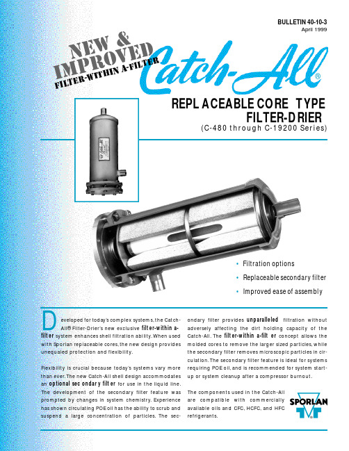
eveloped for today’s co m p l e x sys t e m s ,the Catc h -All® Fi l t e r -D ri e r ’s new exc l u s i v e f i l t er-within a-f i l t er s y s t em enhances shell filtration ability.When used with Spo r lan re p l a c eable co r e s ,the new design prov i d e s unequaled pro t e c tion and flex i b i l i t y.Fl e x i b i l i t y is crucial be c ause tod a y’s sys t ems va r y more than eve r .The new Catc h -A ll shell design acco m m o d a te s an optional sec o n d a r y filt e r for use in the liquid line.The deve l o p m e n t of the seco n d a r y filter fe a t u r e wa s p r o m p t ed by changes in sys t em chemistry.E x p e r i e n c e has shown circ u l a ting POE oil has the ability to scrub and s u s p end a large co n c e n t r ation of part i c l e s .The sec-o n d a r y filter provides u n p a r a l l e l e d f i l t r ation without a d versely affe c ting the dirt holding ca p a c i t y of the Catc h -A l l .The f i l t er-within a-filt e r co n c ept allows the molded co r es to re m o ve the larger sized part i c l e s ,w h i l e the seco n d a r y filter re m o ves micro s c opic particles in cir-c u l a t i o n .The seco n d a r y filter fe a t u r e is ideal for sys t e m s re q u i r ing POE oil,and is re c ommended for sys t em start-up or sys t em cleanup after a co m p r e s s o r b u r n o u t .The co m p o n e n ts used in the Catc h -A l l a r e co m p a tible with co m m e r c i a l l y available oils and CFC,H C F C ,and HFC re f r i g e r a n t s .BULLETIN 40-10-3April 1999REPL ACEABLE CORE TYPEFILTER-DRIER(C-480 through C-19200 Se r i e s)Integral to the redesign are these…DESIGN FEATURES•The Catch-All shell utilizes an exclusive filter-within a-filter construction . The new internal assembly,when used with Sporlan molded cores, provides maximum water capacity, excellent acid removal charac-teristics, the ability to remove products of oil decomposition, and outstanding filtration. The optional replaceable secondary filter offers unsurpassed filtration efficiencies without compromising the Catch-AllÕs ability to hold a large amount of foreign material. The assembly is designed so the cores remove larger sized particles while the secondary filter removes microscopic particles. This unique construction aggressively filters particles circulating in a refrigerant system.•The shell redesign offers flexibility . The new internal assembly can be used with or without the secondary filter. The type of fil-tration needed depends upon the system requirements or appli-cation. Using the assembly without the secondary filter offers the same time tested, field-proven, filtration characteristics expected in a Catch-All Filter-Drier.•The internal construction is designed to improve ease of assem-bly . The molded cores simply slide over the center tube, fol-lowed by spacer plates (if applicable). The outlet plate is fastened to the assembly by a wing screw. With the addition of a spring, the resulting assembly is easy to install and remove.•The seal gasket prevents solid contaminants from bypassing the filter. The assembly is held tight against the gasket by a spring.O-rings are used with the secondary filter to provide a tight seal.•The internal parts are plated steel Ð no plastic parts.•The bolt and nut attachment of the end plate allows for simple,trouble-free installation. The nuts lock against the side of the shell for ease in tightening. Other designs, using cap screws threaded into the flange ring, run the risk of twisting off the head of the screw making removal difficult.•Copper fittings are excellent for fast easy soldering. Fittings are pre-sized for proper fit, and suitable for use with soft solder, sil-ver solder, Sil-Fos, or Phos-Copper. The fittings are brazed to the shell with a high temperature brazing alloy so they never come loose during the brazing operation on the job.•A complete line of fitting sizes are available with solder con-nections from 1/2Ó to 2-1/8Ó ODF.•Heavy steel shells provide high bursting strength and are listed by UnderwritersÕLaboratories Inc. and Canadian Standards Association.•The shell exterior uses an epoxy powder coating to prevent corrosion even under the most adverse condi-tions.Page 2/ BULLETIN 40-10-3The construction illustrated is used on the C-480 through C-19200 Series Catch-All Filter-Driers (ODF Solder models only)manu f actured a f ter 6/99.The C-R420,C-30,000,and C-40,000 Series models differ in construction,but maintain the f ield-proven features which have been used suc-cessfully for many years.C-967Exploded ViewFEATURES®BULLETIN 40-10-3 / Page 3APPLICATIONThe C-480 through C-19200 Series Replaceable Core Type Catch-All Filter-Driers are designed to be used in the liquid line. Place the Catch-All immediately ahead of other liquid line controls, such as the ther-mostatic expansion valve, solenoid valve, and See¥All¨Moisture and Liquid Indicator. When applied in this way, the filter-drier provides maximum protection for the thermostatic expansion valve and solenoid valve from dirt that may be in the system. If the system contains appreciable amounts of moisture, this location gives the best results in protecting the thermostatic expansion valve from freeze-up. If possi-ble, place the filter-drier in a cold location on the liq-uid line. Acid capacity is not affected by differences in liquid line temperature.The secondary filter feature is ideal for systems with POE oil, and is recommended for system start-up or system cleanup after a compressor burnout.Because of flow considerations, the new C-480 through C-19200 Series Replaceable Core Type Catch-All Filter-Driers are not recommended for the suction line. Sporlan manufactures Replaceable Suction Filter(RSF) shells specifically for suction line installations. The RSF shell is designed to allow maximum vapor flow with a minimum pressure drop whether the installer is using filter elements or mold-ed cores.Catch-All Filter-Driers are not recommended in the discharge line. There are better locations. The water capacity in this location is greatly reduced due to the high operating temperature.Catch-All Filter-Driers may be installed in any position, with top or bottom feed. However, it is advisable to mount replaceable core models horizontally so that for-eign material cannot drop into the outlet fitting when the cores are removed. Always observe the flow direction. Catch-Alls must never be subjected to reverse flow.The Catch-All should be installed in the main liquid line for maximum protection. When located in a bypass line, dirt or foreign material may pass into the system through the unprotected line. When a bypass installation is necessary, consult Bulletin 40-10.The components used in the Catch-All are compatible with commercially available CFC, HCFC, and HFC refrigerants and oils. The new internal assemblies are not suitable for use on ammonia systems. All Replaceable Core Type Catch-All Filter-Driers with NPT female connections, supplied with the tie rod construction, are suitable for CFC, HCFC, and HFC refrigerants plus ammonia.SELECTIONThe C-480 through C-19200 Series Catch-All Filter-Driers should be selected in accordance with the Liquid Refrigerant Flow Capacities and Selection Recommendations in Bulletin 40-10. Catch-All shells incorporating the new construction, even with the sec-ondary filter, have liquid flow capacities equal to or slightly greater than the shells using the tie rod con-struction.Water and acid capacities of the Replaceable Core Type Catch-Alls have not changed. Consult Bulletin 40-10 on the water capacities of these models at ARI Standard Conditions. Acid removal is difficult to measure. There are no standard ratings to follow. However, both labo-ratory and field tests have demonstrated that the Catch-All core has far superior acid removal ability Ð many times that available in other driers.Filtration characteristics of a filter-drier are not readily defined or evaluated since laboratory tests cannot accu-rately reproduce the range of conditions and contami-nants seen in an actual system. The ability to filter and hold foreign matter varies with the brand and type of fil-ter-drier. The simplest guide to follow is that filter capacity is proportional to filtering area. Filters should be selected with an adequate reserve capacity to allow for the contamination found in most systems.APPLICATION / SELECTION ®Page 4/ BULLETIN 40-10-3* Two O-rings are required for each internal assembly and are sup-plied with each secondary filter.The O-rings,part no.621-025,can also be purchased separately.Previous Designs –Parts kits for the new internal construction fit in shell Designs B and C.Converting shell Design B does require a thicker outlet retainer ring plate gasket,part no.1288-014.The new internal construction cannot be used in Design A.Consult Bulletin 122 for replacement part specifications for Design A.R eplacement Parts and Kits are available through Sporlan Authorized Wholesalers.AssemblyOptional Secondary FilterShellFlange Bolts and NutsDesign DManufactured June 1999P RINTEDINU.S. OF A. ©C OPYRIGHT 1999 S PORLAN V ALVE C OMPANY , W ASHINGTON , M ISSOURI 15-499Design AManufactured until 1983Design B )Manufactured 1983-1991)Manufactured 1991 - Present(“Press Fit”onto Plate,Outlet Core Retainer)NutShellare included)Tie Rod(3 Req’d)Outlet Screen Gasket (Felt)Tie Rod(3 Req’d)Tie Rod(3 Req’d)Nut NutPlate Gasket)The B and C design can be differentiated by external shell appear-ance. The welded end cap on the outlet of the shell fits inside the body shell on the B version and it slides over the body shell on the C version.(“-P”Type Catch-Alls Only)Retainer Plate Gasket。
阿米亚德自清洗过滤器使用说明书.
6.过滤器必须安装完整,以避免水花溅落到电力元件或控制盘上。
7.如果安装在热水场合,请额外附加一些安全装置以避免烫伤皮肤。
操作、控制与维护
1.在调试、安装过滤器之前应切断电源供应。
2.只有在压力释放之后才能松开或拆卸螺栓。
3.缓慢地打开进口阀门,如果可以,请保持出口阀关闭且旁通阀打开,按下“TEST”按钮操作手动清洗。
4.缓慢打开出口阀门使过滤器逐渐达到正常工作流量。
5.清洗操作应该持续大约16秒,并且可以观察到整个过程中排污阀应该完全开放,16秒过后,排污阀应能立即关闭。确保清洗完全结束后排污阀没有明显的泄漏。
电动控制系统说明
3.方便地靠近过滤器。
4.工作一周以后检查并重紧螺栓。
安装示意图:
备注:标注尺寸:毫米
1.8″CBR线外型过滤器
2.2″排污管
3.8″止回阀
4.8″进口蝶阀
5.8″旁通阀
*打开过滤器所需最小尺寸。
安装示意图:
备注:标注尺寸(毫米)
1.4″CBR型过滤器
2.2″排污管
3.2″排污阀
4.4″止回阀
5.4″进口蝶阀
04
1 1 0 0
12秒
05
0 0 1 0
20分钟
05
0 0 1 0
16秒
06
1 0 1 0
30分钟
06
1 0 1 0
20秒
07
0 1 1 0
45分钟
07
0 1 1 0
25秒
08
1 1 1 0
1小时
08
1 1 1 0
30秒
以色列AGF全塑球形浅层砂滤器的组装和操作说明书

(第一版)
ARKAL 过滤系统有限公司 2003-12
一. 打开 AGF
1. 打开AGF的包装带 2. 将上面的3个腿拿到旁边,将泡沫塑料
拿下来,放在AGF旁边 3. 将AGF侧放在泡沫塑料的上面 4. 将三个腿插入AGF底部 5. 将AGF站立起来,注意要首先让两个腿
单元反洗不启动
4 反洗不停
按图 2 方法查找原因
按图 2 方法解决
5 反洗过于频繁 A. 系统流量太大
调整到合适流量
(一般反冲周期 B.压差或时间设置值太小
调整到合适值
大于一小时) C.沙子黏结
清洗沙子或换沙子
D. 原水太脏
处理原水
E. 反洗不彻底
详见 5
6 反洗不彻底
A. 反洗水压太低
增加进水水压
联系 ARKAL 代理
图 2 连续反洗不停的解决方案
将和阀门连接的控制管取下
无 有
没有控 制气体
用万用表测试 电磁阀的电压
打开阀门盖,观察有 无异物卡住阀门
无 更换电磁阀
有 问题出在控制器
无 修理或更换阀门
有 清除异物
联系 ARKAL 代理
联系 ARKAL 代理
1. 选择沙子:根据过滤的要求充填不同粗细的沙子,对于较粗精度的过
滤 ARKAL 建议采用 2 号粗沙,沙的大小约为 1.2—2mm, 对于精细
的过滤分别充填 2 号和 0 号沙子,0 号沙子的大小为 0.5-0.7mm. 也
可以根据过滤要求,选则其他尺寸的沙子。
2. 检查过滤单元和过滤系统的密封情况:打开
B. 排污管或阀门压阻太大
打开疏通排污管及阀门
C. 杂质太粘
- 1、下载文档前请自行甄别文档内容的完整性,平台不提供额外的编辑、内容补充、找答案等附加服务。
- 2、"仅部分预览"的文档,不可在线预览部分如存在完整性等问题,可反馈申请退款(可完整预览的文档不适用该条件!)。
- 3、如文档侵犯您的权益,请联系客服反馈,我们会尽快为您处理(人工客服工作时间:9:00-18:30)。
过滤模式
(3) 悬浮杂质被拦截在叠片外部和叠片之间。
进口
出口
3.反洗过程
控制器发出信号,关闭进水打开排污,此时:
1) 它过滤单元过滤后的清水从相反的方向进入 该反洗的过滤器的出水口;
2) 橡胶锥斗的裙翼被水的压力打开,水流只能 进入各反洗管;
3) 压力水从安装在反洗管上的喷嘴喷出; 4) 反洗管中的压力水同时也进入活塞盖,推动
切换回到过滤状态,过滤芯压盖靠弹簧
力重新压紧叠片,第一个反洗的过滤头
又回到过滤状态。第二个反洗过滤头及
该系统其后的过滤头都经过同样的运
行程序,顺次完成反洗,每两个过滤头
的反洗间隔 10-30 秒钟(根据设置),
用于维持系统压力,和补充储水罐中的
水。在所有过滤器完成反洗后,系统有
回到初始过滤状态
压缩空气进口
A. 增加进水水压
B. 过滤器叠片受污染 C. 系统设计太小
B. 清洗保养叠片
2 一个或多个过滤 按图 12 方法查找原因 头反洗不启动
按图 12 方法解决
3 反洗不停
按图 13 方法查找原因
按图 13 方法解决
4 反洗过于频繁 A. 系统流量太大 (一般反冲周期 B.压差或时间设置值太小
调整到合适流量 调整到合适值
2. 每月维护
(1) 运行并检查压差启动反洗是否正确,若不正确,则疏通高低压信 号管。 (2) 检查并维护电磁阀 (3) 检查并维护反洗阀 (4) 检查出水压力和排污压力(反洗时) (5) 清洗刚结束后,打开一个过滤头的盖子检查叠片是否清洗干净了 (4) 查看统计数据,根据统计数据分析系统运行状况并适当优化运行
最小的通道
中等的通道
最大的通道
当叠片之间的沟纹累积大量杂质后,过滤器装置通过改变进出水流方向,自动打开压紧 的叠片,并喷射压力水驱动叠片高速旋转,通过压力水的冲刷和旋转的离心力使叠片得到清 洗。然后再改变进出水流向,恢复初始的过滤状态。
3
2. 过滤过程
(1) 叠片被弹簧力和压盖内外压差形成的压紧力而紧 紧地压在一起,形成一个紧密的过滤元件,防止水 中杂质穿透;
压盖向上,松开被其压紧叠片;
排污
5) 沿切线方向喷射的水流驱动松开的叠片快速 旋转,同时冲刷走拦截的杂质;
反冲洗进水
6) 反洗水携带冲刷下来的杂质从排污口排走。
4.反洗压力和精度的关系
足够的压力是保证过滤器有效反洗的关键参数
精度( 微米) 20
55
有效反洗压力
> 5.5 公斤
> 4 公斤
大于 100 微米 > 3 公斤
五、启动运行
1. 关闭出水阀,打开进水阀,打开排污水阀,打开反冲洗进水(对于外源模式),打开辅 助反冲洗压缩空气阀门(空气反洗模式)。确认进水压力不低于背压要求 (外源和空气 反洗模式进水不低于 0.08 Mpa, 外源和压缩空气不低于反冲洗要求压力)。
2. 强制系统反洗,直至出水清澈。强制反洗可以通过控制器指令启动手动反洗,最好反洗 2-3 个周期。
2.外源反洗系列
过滤过程 原水通过进水管和进水三通阀,进入每个过滤单元,穿过过滤单元过滤组件上的过滤叠
片,清水从出水三通阀流后出汇总到水管路流出。
5
反洗过程
(1) 当启动反洗的压差或时间任何一个设定的条件达到时,控制器就发出一个启动反洗的
电信号;
(2) 电磁阀接到电信号后,发送空气信号至反洗阀,使其从过滤状态切换至反洗状态。此
反冲洗模式
4
二、SPIN KLIN 过滤设备运行模式
1. 标准系统(背压反冲洗系列)
过滤过程 原水通过进水管和进水三通阀,进入每个过滤单元,穿过所有过滤单元,清水从汇总到
出水管路流出。 反洗过程 (1) 当启动反洗的压差或时间任何一个设定的条件达到时,控制器就发出一个启动反洗的
电信号; (2) 电磁阀接到电信号后,发送空气信号至反洗阀,使其从过滤状态切换至反洗状态。此
参数,清除运行统计
3.每季维护
打开过滤过滤单元,检查叠片的清洁状态,如有污垢,在酸液中浸泡清 洗后重新装好。
4. 过冬准备:若系统不运行则排空过滤器和系统内积水 5.叠片拆装和清洗步骤
(1) 拧开过滤芯上蝴蝶母 (2) 拆去芯上压盖 (3) 撤去叠片组,放在酸液中浸泡清洗,建议用绳
子把每组叠片栓起来,防止混乱
系统最高工作压力:压缩空气和水都不能大于 10 公斤
工作温度:<70℃
pH:4—13
材质: 过滤头本体:增强尼龙(三寸单元, 两寸单元), 全塑,不锈钢,铸铝(四寸单元);
过滤叠片:聚丙烯/NYLON 塑料
管架:碳钢喷涂聚酯,不锈钢,全塑
阀门:铸铁,全塑,不锈钢
接口:系统进出口:见对应设备外形尺寸图 系统排污口:见对应设备外形尺寸图
大于一小时)
C. 过滤器叠片受污染 D. 原水太脏
清洗保养叠片 处理原水
E. 反洗不彻底
详见 5
5 反洗不彻底
A. 反洗水压太低
增加水压(或压缩空气)
B. 排污管或阀门压阻太大
打开疏通排污管及阀门
C.SK 喷嘴被堵(外源模式)
清理喷嘴,过滤反冲洗外源水
D. 储罐中没有水(空气辅助模式) 提高背压大于 0.1 公斤
时第一个反洗的过滤单元的进出口三通阀同时改变方向,切断进水和出水管,导通反冲
进水和排污管,反冲水进入第一过滤单元并反冲洗第一过元后由排污口排除。反洗过程
一般 15 秒左右(根据设置)。此时其他过滤单元依然在过滤。
(3) 第一个过滤头的反洗结束时间到达时,控制
器终止加给该电磁阀的反洗信号,过滤单元
前后的反洗阀切同时换回到过滤状态,过滤
ARKAL 过滤器
用户使用手册
(第一版)
以色列阿科过滤器有限公司
1
一、 设备工作原理 二、 过滤设备运行模式 三、 设备基本参数 四ቤተ መጻሕፍቲ ባይዱ 调试前准备 五、 启动运行 六、 故障检查与排除 七、 过滤系统停止运行 八、 系统日常维护
2
一、设备工作原理
ARKAL 过滤器的核心技术在于采用了叠片式过滤器机理,通过互相压紧的表面刻有沟 纹的塑料叠片实现了表面过滤与深度过滤的结合。通过巧妙设计的过滤装置实现了过滤、反 洗、自动切换、循环往复的工艺过程。
4.反洗阀切换模式
四寸阀
三寸阀
两寸阀
7
三、设备基本参数
运行压力:0.08—1Mpa, 对于背压反冲洗模式要求满足背压要求
反洗压力:0.3—0.6Mpa,请参照第一章第四节(背压,外源泵或压缩空气需达到规定压力)
控制压缩空气:要求大于 3BAR,流量大于 50L/MIN
反冲洗压缩空气(用于压缩空气辅助反冲洗模式):要求大于指定反洗压力,流量为 300L/MIN
反洗水流量:10 吨/单元/小时 (两寸单元) 20 吨/单元/小时 (三寸单元),
50 吨/单元/小时(四寸单元),
过滤叠片精度: 5,20,55,100,130,200,400 微米
四、调试前准备
1. 检查进出水管连接是否正确 2. 检查反洗,排污管连接是否正确。对于空气辅助模式,检查辅助反冲洗的压缩空气是否 连接正确,压力是否达到要求。(压缩空气应以 6 分以上管连到系统边,再由 8MM 接气管 接入系统,避免用太长的 8MM 管,影响供气量。) 3. 检查系统排气装置是否安装正确 4. 检查控制器及压缩信号管路是否安装正确,压缩空气是否接入控制器 5. 检查控制器的电源是否正确(220V/50Hz) 6. 检查进出水压差开关是否连接正确 进水:高压端与仪表中心的孔道(HP)连接
芯压盖靠弹簧力重新压紧叠片,第一个反洗 的过滤头又回到过滤状态。第二个反洗过滤
反冲洗进口
头及该系统其后的过滤头都经过同样的运行
程序,顺次完成反洗,每两个过滤头的反洗
间隔数秒钟(根据设置),用于维持系统压力。
在所有过滤器完成反洗后,系统有回到初始
过滤状态。
3.空气辅助反冲洗模式
过滤过程 原水通过进水管和进水三通阀,进入每个过滤单元,穿过过滤单元过滤组件上的过滤叠片, 清水从出水三通阀流后出汇总到出水总管,当出水压力大于 0.01 公斤时,有一部分水优先 经过单向阀流入储水罐,并通过储水罐上面的排气排出系统中的空气,然后水由出水总管流 出。 反洗过程 (1) 当启动反洗的压差或时间任何一个设定的条件达到时,控制器就发出一个启动反洗的
时第一个反洗的过滤单元的进口三通阀改变方向,切断进水管,导通排污管,此时出水 在背压作用下进入第一过滤单元并反冲洗第一过单元后由排污口排除。反洗过程一般 15 秒左右(根据设置)。此时其他过滤单元依然在过滤。 (3) 第一个过滤单元的反洗结束时间到达时, 控制器终止加给该电磁阀的反洗信号,反 洗阀切换回到过滤状态,过滤芯压盖靠弹 簧力重新压紧叠片,第一个反洗的过滤单 元又回到过滤状态。第二个反洗过滤头及 该系统其后的过滤头都经过同样的运行程 序,顺次完成反洗,每两个过滤头的反洗 间隔数秒钟(根据设置),用于维持系统压力。在所有过滤器完成反洗后,系统又回到 初始过滤状态。
3. 慢慢开启出水阀,实行过滤。 4. 重新调整出水阀的开启,以确保流量在设计范围内,若没有流量表,则控制进出口压差 在 0.05-0.2 公斤之间。 5.对于空气辅助反冲洗要求调整出水阀,使背压大于 0.1 公斤,确保出水能进入储罐。
9
六、故障检查与排除
序 现象
原因
解决方法
号
1 出水流量太小 A. 进水水压太低
(1) 人工启动反冲洗 (2) 依次关闭进水阀,出水阀,气源阀 (3) 断开控制器电源 (4)打开排污口,释放系统内压力和水 (5)打开各个过滤单元外壳,清理保养叠片后重新装好,等待下次使用。