高速过滤器操作说明书剖析
超滤操作说明书
安全使用注意事项出于本装置的性能及使用安全性考虑,操作人员必须遵守以下使用原则:1.操作人员必须具备机械、电气以及化学的基本知识和常识。
2.操作人员必须熟悉本装置的性能、原理及使用方法等。
未经教育的其他人员禁止操作。
3.定期进行点检。
4.点检时发现设备有破损、漏水等不良现象,必须及时进行修复。
5.在进行点检或修理时,必须注意防止误动作。
6.药品的添加及储存时应注意安全,部分药品具有腐蚀性。
第一章:概要简介本使用说明书详细阐述了为贵公司提供的超滤设备的全部操作方法及控制原理。
装置中所属的设备、仪表,如:泵类、减压阀、压力表、流量计、液位计等都附有各自设备、仪表的使用维护说明书及产品简介等资料,请参考阅读,并熟悉操作方法。
操作人员在操作本装置前务必要对本操作说明书及各设备、仪表的技术资料给予详细阅读并充分理解;要严格按照本操作说明书标准的内容执行系统的操作与维护,任何违反本操作说明书要求的操作都可能会造成系统的运行故障、设备损坏等问题,甚至会引发人身伤害事故。
1.2 处理工艺概要本处理装置包括滤芯过滤和膜别离等处理工艺。
1.2.1滤芯过滤处理工艺在原水进入超滤系统前,设置了保安过滤器,将可能造成膜损坏的、较大的机械性杂质过滤掉。
1.2.2膜别离处理工艺经保安过滤器处理后的水进入超滤膜,能有效的降低原水的浊度及细菌。
1.3 处理设备概要①预处理设备┅┅保安过滤器。
②超滤设备┅┅超滤膜单元。
③清洗系统┅┅清洗设备。
④加药系统┅┅次氯酸钠加药设备。
第二章:处理系统原理2.1预处理保安过滤器为防治原水中有异物进入微滤膜系统,对膜造成损坏,在原水进入膜系统之前,设置了过滤精度为10μ的保安过滤器,将可能造成膜损坏的、较大的机械性质过杂滤掉,保证了微滤的进水要求。
2.2超滤处理利用超滤膜能有效地去除水中的微粒、胶体、有机物和病菌等,能够去除少量的置换入水中的离子等,以保证出水的水质符合要求。
超滤膜主要有以下的性能和作用:☆高精度:超滤能彻底滤除水中细菌、铁锈、胶体、大分子有机物等物质。
高速过滤器操作说明

高速过滤器操作说明高速过滤器操作说明1、介绍1.1 系统概述高速过滤器是一种用于网络数据包分析和过滤的技术。
它能够在高速网络传输中实现对特定数据包的快速检测和处理。
1.2 功能特点- 高效的数据包过滤:能够根据预设的规则对数据包进行快速过滤和分析。
- 多种过滤模式:支持基于IP地质、端口号、协议类型等多种过滤模式。
- 灵活的规则设置:用户可以根据需求设置各种复杂的过滤规则。
- 高速传输能力:能够在高速网络环境下实现快速数据包的处理和转发。
2、安装与配置2.1 硬件要求- 一台支持高速网络传输的服务器- 网络交换机或路由器2.2 软件安装请参考附件中的安装指南,按照步骤进行软件的安装和配置。
3、高速过滤器的使用3.1 过滤规则设置在命令行界面或图形界面中,使用过滤器的配置工具进行过滤规则的设置。
可以按需求设置源IP地质、目的IP地质、端口号、协议类型等过滤条件。
3.2 过滤规则的生效配置完过滤规则后,保存并生效配置。
系统将根据设置的过滤规则,对传入的数据包进行处理和过滤。
3.3 日志记录和分析高速过滤器能够记录被过滤的数据包和相关事件,并相应的日志文件。
用户可以通过日志文件对网络流量进行分析和监控。
4、附件- 安装指南:包括软件安装和配置的详细步骤。
- 示例配置文件:展示常见过滤规则的配置示例。
5、法律名词及注释- 高速过滤器:指本文档中所涉及的网络数据包过滤技术。
- IP地质:Internet Protocol的缩写,用于标识互联网上的设备。
- 端口号:用于标识一个应用程序或服务在网络上的唯一标识符。
过滤器使用说明书

微孔过滤器ZG-10.0使用说明书制作单位:生产基地:公司电话:公司传真:邮 编:编制日期:目录一、 产品介绍 (3)二、产品特点 (3)三、滤芯的选择 (3)四、设备技术参数 (4)五、使用说明 (4)六、操作注意事项 (6)七、设备的维护与保养 (6)八、售后服务承诺 (7)九、合格证 (7)十、随机附件表 (8)一、产品介绍:本设备可用于食品、乳品、饮料、酒类、中药、化工行业的液体物料的气体的过滤。
采用折叠式滤芯,折叠式滤芯是一种先进的固定型深层过滤芯,过滤公称精度范围可以从0.1μm直600.1μm。
滤膜不受进料压力波动而影响过滤精度。
其特有的低压差,高通量、良好的过滤精度能较低的经济费用成为取代线绕式、棉饼和纸板等非固定型过滤芯的新型滤芯而深受用户欢迎。
二、产品特点:①化学相容性广、流通量大、压差低、使用寿命长。
②过滤精度范围广、选择度大、可满足各种应用场合。
③采用热熔工艺,牢固且无释放物污染产品。
三、滤芯的选择:1、滤芯的用途很广泛,滤芯的品种、规格较多,选择型号是很重要的。
根据用途可分为过滤液体和气体二种,规格大小可以分为5〃、10〃、20〃、30〃和40〃等。
工作压力一般在0.1Mpa—0.4 Mpa。
由于滤芯孔径不同,其流量也不尽相同,如0.2um—0.4 um过滤沌水的标准在300—500kg/h,如果要提高每小时的过滤量,则可以用多芯或20〃、30〃、40〃英寸组合,例如要过滤5t/h的无菌水,则可以选用0.2 um,30英寸7芯的过滤器。
若过滤杂质多且有粘度,则应添加前置预过滤设备。
气体的过滤与液体过滤稍有不同,它的过滤量以每分钟立方气体来计算。
10英寸滤芯,孔径φ0.22 um,压力在0.12 Mpa,压差在0.01 Mpa时,流量为4-6m3/min,在发酵工业上广泛应用。
2 、合适的滤芯,选用适当的孔径,若要除菌则选用0.2um-0.5um孔径的滤芯、药用针剂、抗菌素、血制品等用聚砜滤芯。
超滤设备操作说明

超滤设备操作说明第一部分:设备概述超滤设备是一种常见的水处理设备,可有效去除水中的悬浮颗粒、胶体、大分子有机物和细菌等杂质,适用于工业、农村和家庭等不同场合的水处理需求。
第二部分:设备组成1.超滤膜组件:超滤膜是超滤设备的核心部件,由多个微孔组成,可根据需要选择不同孔径的膜。
2.进水管道:将待处理的水引入超滤设备。
3.出水管道:将经过超滤的水排出设备。
4.泵:用于推动水流经过超滤膜进行过滤。
5.控制面板:用于设置设备运行参数和监控设备状态。
第三部分:设备操作步骤1.确保设备和管道连接正常,没有泄漏。
2.打开进水阀门,将待处理的水引入设备。
水流应该从设备的进水管道流入。
3.根据水质和需求设置超滤设备运行参数。
通常包括流量、超滤膜的清洗和更换周期等。
4.打开泵电源,启动泵,使水流经过超滤膜组件。
此时,水将被过滤,杂质将被滞留在超滤膜上,净水将从出水管道排出。
5.在设备运行过程中,定期检查设备状态,确保超滤膜和管道的畅通。
6.根据设备使用时间和运行情况,适时进行超滤膜的清洗或更换。
清洗方法包括物理清洗和化学清洗,可根据具体情况选择合适的方法。
7.当不再需要使用设备时,关闭泵电源,关闭进水阀门和出水阀门,将设备进行保养和维护。
第四部分:设备维护和保养1.定期检查设备状态,确保各部件正常运行,水流畅通,没有堵塞。
2.定期清洗超滤膜,防止污秽物堆积。
清洗方法根据具体情况选择,可参考超滤设备的使用说明书。
3.定期更换超滤膜,根据设备的使用时间和性能变化情况确定更换周期。
4.定期清洗和消毒设备的管道和容器,避免细菌和物质积聚。
5.定期保养设备的泵和阀门,确保其正常运行。
6.定期对设备进行维护和检修,清除设备内的杂质,保持设备的功能完好。
第五部分:设备故障处理1.设备不能启动时,检查电源是否正常,检查泵和电路是否损坏。
2.设备运行时水流缓慢或无法正常出水时,检查设备是否被堵塞,是否需要清洗超滤膜。
3.设备运行时出现漏水现象时,检查管道是否连接松动或破损。
高速过滤器技术说明2
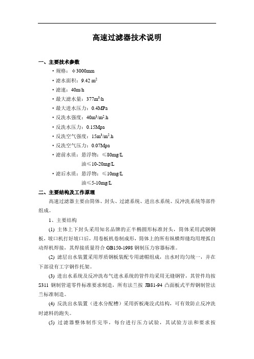
高速过滤器技术说明一、主要技术参数·规格:φ3000mm·滤水面积:9.42 m2·滤速:40m/h·最大滤水量:377m3/h·最大进水压力:0.4MPa·反洗水强度:40m3/m2.h·反洗水压力:0.15Mpa·反洗空气强度:15m3/m2.h·反洗空气压力:0.07Mpa·滤前水质:悬浮物:≤80mg/L油≤10-20mg/L·滤后水质:悬浮物:≤10mg/L油≤5-10mg/L二、主要结构及工作原理高速过滤器主要由筒体、封头、过滤系统、进出水系统、反冲洗系统等部件组成。
1、主要结构(1) 主体上下封头采用知名品牌的正半椭圆形标准封头,筒体采用武钢钢板,坡口机打好坡口后,用卷板机卷制成形,筒体上的所有纵横焊缝均用埋弧自动焊机焊接,其焊接质量符合GB150-1998钢制压力容器标准。
(2) 滤层出水装置采用厚质钢板装配专用滤帽组成,出水时均匀统一,并在下部设有工字钢作托架。
(3) 进出水系统及反冲洗布气进水系统的管件均采用无缝钢管,其管件均按S311钢制管道零件标准要求制造,所有法兰按JB81-94凸面板式平焊钢制管法兰标准制造。
(4) 反洗出水装置(进水分配槽)采用折板淹没式结构,可有效防止反冲洗时滤料的跑失。
(5) 过滤器整体制作完毕,每台进行压力试验,其试验方法和要求按GB150-1998钢制压力容器标准和JB2932-86水处理设备制造技术条件标准进行。
2、工作原理原水流入罐体内,由上而下经过滤料将原水中的油、悬浮物等予以截留,滤后水流出罐体。
当进出水压力差增大、滤速减漫、出水量降低时,反洗装置工作、反冲掉吸附于滤料上的杂物,保证过滤器的正常运行。
三、主要部件材质·主体:Q235A碳钢·滤板:Q235A碳钢·托架:Q235A碳钢·滤头:ABS·滤料:无烟煤、石英砂、鹅卵石·进出水管:无缝钢管·反洗水、气管:无缝钢管·紧固件:Q235A碳钢三、GSL型外形结构所有阀门布置及动作A.B.C.D.E管法兰公称压力0.6MPa(GB/T9119-2000),方位分甲型和乙型两种(对称布置)。
过滤器操作指南说明书

过滤器操作指南说明书一、引言过滤器是一种常用的设备,用于过滤和清洁物质,以确保其质量和安全性。
本指南将详细介绍过滤器的操作步骤和注意事项,以便用户正确操作和维护过滤器,并最大限度地发挥其功能和效果。
二、过滤器简介1. 过滤器类型:本款过滤器为[指明具体型号或类型],主要用于[指明使用场景]。
2. 主要组件:过滤器由以下主要组件构成:- 过滤介质:[描述过滤介质的特点和材料];- 滤芯:[描述滤芯的类型和作用];- 进出口管道:[描述进出口管道的位置和连接方式];- 支架:[描述支架的结构和材料];- 控制阀:[描述控制阀的功能和使用方法]。
三、操作步骤在操作过滤器之前,请确保已经了解其使用方法,并按照以下步骤进行操作:1. 检查过滤器:检查过滤器的外观是否完好无损,如有损坏或松动的部件,请勿使用,并及时进行修理或更换。
2. 准备工作:根据实际需要,确认进出口管道已正确连接,并打开进水阀和出水阀。
3. 过滤介质清洗:根据使用时间和需求,定期进行过滤介质的清洗。
具体方法为[描述清洗方法和步骤]。
清洗过滤介质时,务必戴好防护手套和口罩,以防止对人体产生不良影响。
4. 滤芯更换:根据滤芯的使用寿命和建议更换周期,定期更换滤芯。
具体步骤为[描述滤芯更换方法和步骤]。
更换滤芯时,需关闭进水阀和出水阀,并确保系统压力已释放。
5. 过滤器操作:打开进水阀和出水阀,将液体通过过滤器进行过滤。
请注意过滤液的流速,避免超过过滤器的最大流速。
6. 控制阀操作:根据需要,通过控制阀控制过滤器的运行状态和流量。
具体方法为[描述控制阀的使用方法和步骤]。
务必在操作控制阀之前,确保已关闭进水阀和出水阀。
四、注意事项为确保过滤器的正常运行和用户的安全,请注意以下事项:1. 使用环境:请将过滤器安放在干燥、通风良好的环境中,避免过滤器长时间暴露在高温、潮湿或腐蚀性气体中。
2. 维护保养:定期对过滤器进行维护保养,清洗过滤介质和更换滤芯。
海华Pro系列高速沙筒过滤器产品说明书
Your Hayward Pro Series high-rate sand filter is a high performance, totally corrosion-proof filter that blends superior flow characteristics and features with ease of operation. It represents the very latest in high-rate sand filter technology. It is virtually foolproof in design and operation and when installed, operated and maintained according to instructions, your filter will produce clear, sparkling water with only the least attention and care.HOW IT WORKSYour filter uses special filter sand to remove dirt particles from pool water. The filter sand is loaded into the filter tank and functions as the permanent dirt removing media. The pool water, which contains suspended dirt particles, is pumped through your piping system and is automatically directed by the patented filter control valve to the top of the filter tank. As the pool water is pumped through the filter sand, dirt particles are trapped by the sand bed, and filtered out. The cleaned pool water is returned from the bottom of the filter tank, through the control valve and back to the pool through the piping system. This entire sequence is continuous and automatic and provides for total recirculation of pool water through your filter and piping system.After a period of time, the accumulated dirt in the filter causes a resistance to flow, and the flow diminishes. This means it is time to clean (backwash) your filter. With the control valve in the backwash position, the water flow is automatically reversed through the filter so that it is directed to the bottom of the tank, up through the sand, flushing the previously trapped dirt and debris out the waste line. Once the filter is backwashed (cleaned) of dirt, the control valve is manually resequenced to Rinse, and then Filter, to resume normal filtering.INSTALLATIONOnly simple tools (screwdriver and wrenches), plus pipe sealant for plastic adapters, are required to install and/or service the filter.The filter system should be installed, not more than 6 feet above pool water level, on a level concrete slab, very firm ground, or equivalent, as recommended by your pool dealer. Position the filter so that the piping connections, control valve and winter drain are convenient and accessible for operation, service and winterizing.Assemble filter control valve to filter. Align the two (2) valve pipe connections, with O-rings in place, with the two openings in the side of the filter tank and press in firmly. Secure the assembly to the tank connections with the two bulkhead locknuts. Do not overtighten.1.2.IS210SV-99MODELS S210SV, S244SV23-1/2”(60 cm)35-3/4” (91 cm) S210SV 40” (102 cm) S244SVSPECIFICATIONSMODEL NUMBER S210SV S244SVEFFECTIVE FILTRATION AREAFT 22.23.14M 20.210.3GPM 4462LPM 167235PSI 23PSI 5050BAR 0.140.21BAR 3.453.45INCH 1818INCH 1818MM 457457MM 457457LBS 200300KGS 91136FILTER SAND**0.45-0.550.45-0.55DESIGNFLOW RATE*PRESSURE LOSS AT DESIGN FLOW RATE MAXIMUM WORKING PRESSURE REQUIRED CLEARANCESIDE ABOVEMEDIA REQUIREDTYPE AMOUNT PARTSModels S210SV, S244SV*Based on 20 GPM/ft.or 814 LPM/m (maximum allowable NSF rating).**Also known as No. 20 or No. 1/2 Silica Sand.NOTE:ANSI/NSPI-4 Article V, standard for above-ground and on-ground pools, advises that components such as the filtration system, pumps and heater be positioned so as to prevent their being used as a means of access to the pool by young children.REF.NO.1234567a 7b 89a 9b10a 10b 11a 11b 1213a 13b 1415161718192021NO.REQ’D.111111111111101111112212PART NO.ECX270861DEX2400S SX200Z5SX244K GMX600F GMX600NM SX210AA2SX244AA2SX244G SX210CD SX244CD1SX210CD2SX244CD2SX200Q SX240D SX240MACX3000Z2CX1100Z4SX200Z2SX180G SX180H SX200J SX220Z3SX244PSPX410X602S SX200Z4DESCRIPTIONPressure Gauge Manual Air Relief Cap O-Ring, 13/16”O.D.Top Closure Dome Valve/Tank O-Ring Flange Clamp (Valve-Tank)Filter Tank (S210S)Filter Tank (S244S)Top DiffuserTop Elbow Assembly (S210S)Top Elbow Assembly (S244S)Bottom Elbow Assembly (S210S)Bottom Elbow Assembly (S244S)Lateral (S210S)Lateral (S220S, S244S)Lateral Holder Assembly Plastic Air Tube (S210S)Plastic Air Tube (S244S)Air Tube Lock Screw Gasket Drain CapFilter Support Stand O-RingBulkhead FittingSlide Control Valve O-Ringa bAssemble pump and pump mounting base (if supplied) to the filter according to instructions packed with the base.Loading sand media. Filter sand media is loaded through the top opening of the filter.Remove the top diffuser from the internal diffuserelbow pipe and place flexible, automatic air relieftube to the side, out of the way, inside the tank.Cap the internal diffuser elbow pipe with protectioncap provided to prevent sand from entering it.It is good practice to fill tank approximately 1/2 waywith water to provide a cushioning effect when thefilter sand is poured in. This helps protect theunderdrain laterals from excessive shock. (Be surethe drain cap is securely in place on drain pipe. Applywrench to flats on pipe when tightening cap.) Note:Check to confirm all laterals are in the downposition before loading with sand. (See Figure Aon Page 2).Carefully pour in correct amount and grade of filtersand, as specified. Sand surface should be leveledand should come to about the middle of the filtertank. Use no more than the recommended amount ofsand.Remove protection cap from internal diffuser elbowpipe.Replace diffuser on internal diffuser elbow pipe,positioning automatic air relief tube through the holeprovided in the diffuser.Place valve flange clamp around neck of tank. Do notovertighten. Wipe filter flange clean.Insert top closure dome (with flange O-ring in place)into the tank neck. Place clamp around dome flangeand tank flange and tighten with screwdriver, tappingaround clamp with screwdriver handle to help seatflange clamp.Connect pump to control valve opening marked Port B (middle). Make return to pool pipe connection to control valve opening marked Port E (bottom) and complete other necessary plumbing connections, suction lines to pump, waste, etc.Make electrical connections to pump per pump instructions.To prevent water leakage, be sure drain cap is securely in place and all pipe connections are tight.INITIAL START-UP OF FILTERBe sure correct amount of filter sand media is in tank and that all connections have been made and are secure.Set filter control valve to BACKWASH*. (To prevent damage to control valve seal, always depress handle before turning).Prime and start pump according to pump instructions (be sure all suction and return lines are open), allowing the filter tank to fill with water. CAUTION: All suction and discharge valves must be open when starting the system. Failure to do so could cause severe personal injury and/or property damage.Once water flow is steady out the waste line, run the pump for at least 2 minutes. This initial backwashing of the filter is recommended to remove any impurities or fine sand particles in the sand media.Turn pump off and set valve to FILTER position (handle UP and locked) and restart pump. Your filter is now operating in the normal filter mode, filtering particles from the pool water.Adjust pool suction and return valves to achieve desired flow. Check system and filter for water leaks and tighten connections, bolts, nuts, as required.Note the initial pressure gauge reading when the filter is clean. (It will vary from pool to pool depending upon the pump and general piping system.) As the filter removes dirt and impurities from the pool water, the accumulation in the filter will cause the pressure to rise and flow to diminish. When the pressure gauge reading is 6-8 PSI(0.41-0.55 BAR) higher than the initial “clean” pressureyou noted, it is time to backwash (clean) the filter (see BACKWASH under Filter Control Valve Functions).NOTE: During initial clean-up of the pool water it may be necessary to backwash frequently due to the unusually heavy initial dirt load in the water.IMPORTANT: To prevent unnecessary strain on piping system and valving, always shut off pump before switching Filter Control Valve positions.To prevent damage to the pump and filter and for proper operation of the system, clean pump strainer and skimmer baskets regularly.FILTER CONTROL VALVE FUNCTIONSFILTER and BACKWASH selections are provided for all necessary operational functions.FILTER—Set valve to FILTER for normal filtering. Also use for vacuuming (handle in UP position).BACKWASH—For pressure cleaning filter (handle in DOWN position).VACUUMING—Vacuuming can be performed directly into the filter. Set valve in FILTER position.3. 4.a.b.c.d.e.f.g.h. 5.6. 7.1. 2.3.4. 5. 6.*NOTE:For new concrete or gunite pools, or where there is a large amount of plaster dust or debris—start filter in FILTER position (not BACKWASH) to prevent clogging of underdrain laterals.PROBLEM SOLVING LISTLOW WATER FLOW SHORT FILTER CYCLES POOL WATER WON’T CLEAR UPCheck skimmer and pump strainer baskets for debris.Check for restrictions in intake and discharge lines.Check for air leak in intake line (indicated by bubbles returning to pool). Backwash filter.Check for algae in pool andsuperchlorinate as required.Be sure chlorine and pHlevels are in proper range(adjust as required).Check surface of filter sandfor crusting or caking(remove 1”of sand ifnecessary).Check chlorine, pH and totalalkalinity levels and adjustas required.Be sure flow rate throughfilter is sufficient.Operate filter for longer periods.Be sure control valve is seton “Filter” position.1. 2. 3. 4.1.2.3.1.2.3.4.REMEDYPOOL CHEMISTRY GUIDELINESACTION REQUIRED TO CORRECT POOL CHEMISTRYTO RAISE TO LOWER SUGGESTED POOL CHEMISTRY LEVELSpHTOTAL ALKALINITY CHLORINE (UNSTABILIZED) CHLORINE (STABILIZED) CHLORINE STABILIZER (Cyanuric Acid)7.2 to 7.6100 to 130 ppm0.3 to 1.0 ppm1.0 to 3.0 ppm40 to 70 ppmAdd Soda AshAdd Sodium BicarbonateAdd Chlorine ChemicalAdd Chlorine ChemicalAdd StabilizerAdd Muriatic Acid or Sodium BisulphateAdd Muriatic AcidNo action - chlorine will naturally dissipateNo action - chlorine will naturally dissipateDilution - partially drain & refill pool with waterthat has not been treated with Cyanuric Acid.©1999 Hayward Printed in U.S.A.WINTERIZINGCompletely drain tank by unscrewing drain cap at base of filter tank. Leave cap off during winter. Drain filter control valve.Drain and winterize pump according to pump instructions. PLEASE REALIZE . . .Pure, clear swimming pool water is a combination of two factors—adequate filtration and proper water chemistry balance. One without the other will not give the clean water you desire.Your filter system is designed for continuous operation. However, this is not necessary for most swimming pools. You can determine your filter operation schedule based on your pool size and usage. Be sure to operate your filtration SERVICE & REPAIRSConsult your local authorized Hayward dealer or service center. No returns may be made directly to the factory without the expressed written authorization of Hayward Pool Products, Inc.system long enough each day to obtain at least one complete turnover of your pool water.To properly sanitize your pool, maintain a free chlorine level of 1 to 3 ppm and a pH range of 7.2 to 7.6. Insufficient chlorine or an out of balance pH level will permit algae and bacteria to grow in your pool and make it difficult for your filter to properly clean the pool water.Rev. 1/99。
高速过滤器操作说明
高速过滤器操作维护手册高速过滤器1、高速过滤器工作原理高速过滤器是利用石英砂,无烟煤作滤料,过滤水中构成浊度的悬浮物质,确保出水中的浊度符合用水要求。
2、高速过滤器运行程序2.1通水过程原水(待过滤的水)从过滤器上部进水管,经过过滤器上部的分水机构将水均匀地分布到过滤层两面,通过过滤层的过滤再经过多个滤头的过滤,便为经处理过的清净水,然后从处理水的出水管向罐外排出供用户使用。
2.2反洗过程当通水过滤一定时间后,由于在滤层及滤头表面的杂质不断积累,产生水阻,出水流量减少,原水进口和净水出口产生压降,这时便需要进行反洗,也可预置一定的时间周期进行反洗。
2.2.1空气反洗当过滤器的压力差达到设定值时,就在过滤器底部的反洗空气入口导入一定压力和强度的空气,经过反洗空气的均匀散气,通过滤头对过滤层的滤料进行搅拌疏散,滤料便与粘着物分离,空气则从过滤器顶部向外排出。
2.2.2通水反洗经过空气疏散和洗净后,为了将分离后的粘着物向外排出,将一定压力和强度反洗水从过滤器下部导入,通过分散板和过滤板滤头的分散作用,对过滤层进行由下而上的清洗,使粘着物与滤料分离,与反洗的污水一起排出罐外,这时整个反洗过程结束,过滤器便进行正常的通水过滤。
3、操作过程的说明3.1调整过滤器分手动和自运控制运行方式3.2运行时,打开1台进水泵、进水阀、排气阀,等罐内空气排空后关闭排气阀,打开初滤排水阀,运行5分钟后关闭初滤排水阀,打开出水阀进入正常运行;3.3排气阀、初滤排水阀设有时间控制,可调节开关阀的时间,调节范围从0~5分钟之间,具体时间设定现场调试后确定;3.4气反洗,关闭进水阀、出水阀,打开排气阀、找开气洗进气阀,冲洗0~2分钟后关闭气洗进气阀3.5水反洗,关闭进水阀、出水阀,打开反洗进水阀、反洗排水阀,再启动另一台备用水泵,冲洗5~8分钟后关闭反冲洗(备用)泵,关闭反洗进水阀、反洗出水阀、排气阀;3.6反冲洗结束后进入过滤状态,周而复始的连续运行。
高效过滤器操作使用维护说明书
高效过滤器操作使用维护说明书高效过滤器操作使用维护说明书1. 基本参数1.1 运行滤速:8m/h1.2 进水浊度: <5mg/L1.3 出水浊度: <1mg/L1.4 反洗强度:8L/㎡·S1.5 气洗强度:12L/㎡·S1.6 反洗时间:4-6min1.7 工作温度:5-40℃1.8 工作压力:≤0.6MPa1.9 滤料高度:1200mm1.10 填料成分:石英砂、无烟煤、鹅卵石2. 结构及工作原理原水在管道内加入絮凝剂,絮凝剂在水中发生离子水解和聚合过程,水中胶体粒子对水解及聚集的各种产物进行强烈的吸附,使粒子表面电荷和扩散厚度同时降低,因而粒子间相互排斥能降低,相互接近而凝聚,水解产生的聚合物被两个以上的胶体吸附后,在粒子间产生架桥联接,逐步形成较大的絮凝体,经过高效过滤器时,为滤料载留。
高效过滤器是以成层状的石英砂、无烟煤作为床层.床的顶层由最轻和最粗品级的材料组成,而最重和最细品级的材料放在床的低部。
其原理为按深度过滤--水中较大的颗粒在顶层被去除,较小的颗粒在过滤器介质的较深处被去除。
从而使水质达到粗过滤后的标准。
多介质过滤器可去除水中水中的悬浮物、有机物、胶质颗粒、微生物、氯、嗅味及部分重金属离子等,并降低水的SDI值,满足深层净化的水质要求。
该设备具有造价低廉,运行费用低,操作简单;滤料有石英砂、无烟煤、鹅卵石,经过反洗,可多次使用,滤料使用寿命长等特点。
高效过滤器的吸附是一种物理吸附,按滤料的填装方式大体可分为松散区(粗砂)、紧密区(细砂),悬浮物质在松散区主工通过流动接触产生接触凝聚作用,所以该区域截留较大颗粒的悬浮物质,在紧密区主要是惯性碰撞及悬浮颗粒间的吸附作用,所以该区域是截留较小颗粒的悬浮物质。
当高效过滤器因截留过量的机械杂质而影响其正常工作,则可用反冲洗的方法来进行清洗。
利用逆向进水,同时通入压缩空气,进行气水混合擦洗,使过高效过滤器内滤层松动,可使粘附于石英砂表面的截留物剥离并被反冲水流带走,有利于排除滤层中的沉渣、悬浮物等,并防止滤料板结,使其充分恢复截污能力,从而达到清洗的目的。
过滤器使用说明书
过滤器使用说明书第一部分:简介过滤器是一种常用的设备,用于过滤固体颗粒或杂质,使液体或气体得以净化。
它被广泛应用于各个领域,包括水处理、食品加工、制药和化工等行业。
本说明书将介绍过滤器的使用方法和注意事项,以帮助用户正确使用该设备。
第二部分:过滤器的分类过滤器可以根据不同的过滤原理和结构进行分类。
常见的过滤器类型包括:滤网式过滤器、滤筒式过滤器、滤芯式过滤器和活性炭过滤器等。
在选择过滤器时,用户应根据应用领域和过滤需求进行选型。
第三部分:使用方法1. 准备工作:a. 检查设备是否完好,包括过滤器本体、滤芯等部件;b. 确保过滤器的进出口连接正确、牢固;c. 根据过滤要求选择合适的滤芯或滤网。
2. 安装过滤器:a. 将过滤器安装在合适的位置,确保不会受到冲击或振动;b. 确保设备的进出口与管道连接紧密,无泄漏;c. 根据具体型号,在进出口管道处安装适当的阀门和流量计。
3. 过滤器的操作:a. 打开进出口阀门,使液体或气体通过过滤器;b. 根据需要调节流量大小,注意在规定的压力范围内操作;c. 定期观察过滤器的运行状态,如发现问题及时维修或更换滤芯;d. 当维修或更换滤芯时,先关闭进出口管道的阀门,避免液体或气体外溢。
4. 清洗和维护:a. 根据使用情况,定期清洗过滤器,防止堵塞和损坏;b. 使用适当的清洁剂或水进行清洗,避免使用腐蚀性物质;c. 清洗后彻底冲洗并晾干过滤器,确保无水渍残留。
第四部分:注意事项1. 使用过滤器前,请确保详细阅读该设备的操作手册,并按照要求使用;2. 定期检查过滤器的工作状态,如发现异常请及时处理,避免影响正常使用;3. 避免将过滤器暴露在严重的振动或冲击环境中,以免影响其过滤效果;4. 根据过滤器的使用寿命,定期更换滤芯或滤网,避免过滤效果下降;5. 避免将过滤器置于高温或低温环境中,以免损坏设备;6. 使用过滤器时,需注意操作的安全,避免发生意外事故。
第五部分:常见故障及解决方法1. 过滤效果降低:a. 检查滤芯是否需要更换,如需要更换请按照要求进行;b. 检查过滤器是否被杂质堵塞,如有堵塞请进行清洗。
- 1、下载文档前请自行甄别文档内容的完整性,平台不提供额外的编辑、内容补充、找答案等附加服务。
- 2、"仅部分预览"的文档,不可在线预览部分如存在完整性等问题,可反馈申请退款(可完整预览的文档不适用该条件!)。
- 3、如文档侵犯您的权益,请联系客服反馈,我们会尽快为您处理(人工客服工作时间:9:00-18:30)。
攀钢动力厂四水站净环水系统改造工程
TGSL-3高速过滤器
操
作
维
护
书
宜兴市华通环保设备有限公司
目录
1、设备概述 (2)
2、技术性能 (2)
3、工艺设计说明 (3)
4、单项设备参数 (4)
5、操作要求 (6)
6、示意图 (7)
-1-
TGSL-3高速过滤器操作说明书
一、设备概述
GSL型快速过滤器在原水悬浮物较多的情况下能确保出水水质的高质量,具有过滤速度高、处理水量大、占地面积小等优点。
其操作分为人工操作和单台(或多台)程序控制自动操作两种。
GSL型快速过滤器不仅适用于过滤悬浮物较多的原水,而且在循环供水系统中使用可改善水质,提高水的循环利用率,节约用水,是当前工业水处理设施中必备的设备。
我公司生产的GSL型快速过滤器由冶金部北京钢铁研究总院设计,经我公司多年的制作经验及不断吸取用户的反馈意见,产品性能得到大大的改进。
本产品广泛用于钢铁行业中的净化处理轧钢、连铸的浊水(含有氧化铁皮及油质),以及循环水系统中旁滤处理,取得了十分满意的效果。
二、TGSL-3高速过滤器技术性能
1、设备筒体最大直径:Φ3020
2、底座最大直径:Φ3280
3、设备高度:H7100㎜
4、滤水面积:7.07㎡
5、最高滤速:V40m/h
-2-
6、最大滤水量:270m3/h
7、最大进水压力:≯3kgf/cm2
8、进水悬浮物含量:≤40mg/l
9、出水悬浮物含量:≤10mg/l
10、过滤器内平均压力损失:~0.5kgf/cm2
11、反洗水强度:40m3/㎡h
12、反洗水压力: 1.5kgf/cm2
13、反洗空气强度:15m3/㎡h
14、反洗空气压力:0.7kgf/cm2
15、设备运行重量:61.8吨
三、工艺设计说明
设备本体材质Q235A,内部用醇酸材料防腐,以卵石为承托,用无烟煤、石英砂作滤层。
设备成型体为圆柱体,上部和中间用旋压式封头作耐压体,底部以平面方式和基础接
3.1、进水系统
由于高速过滤器滤速40m/h,如果高流速进水由上而下运行,将导致不能形成滤膜因而影响出水水质,目前高速过滤器设计的进水系统由缓冲带、中央进水管组成,进水方式为逆流进水,滤膜受冲击问题迎刃而解。
-3-
3.2、布水系统
原水经中央进水管流至压力舱顶部的分流散压式布水器中,分流散压式布水器由分流锥体和散压布水锥体组成,由散压布水锥体将水均匀地流向滤膜,使滤膜受不到冲击。
在运行中滤速短时间大于40m/h或小于40m/h时由于分流散压式布水器的作用,都将不会改变出水水质的稳定性。
布水系统也是反洗时的收水口,以往的高速过滤器在反洗时会出现跑砂现象,本套设备在反冲洗时由于分流散压式布水器的散压布水锥体,锥体朝下,反洗水冲击到锥体时,将大颗粒挡住,泥砂状颗粒和污水经收水口流出,在发生短时间误操作大流量反洗(超过正常反洗流量)时也不会产生跑料现象。
3.3、排水系统
有多个我公司生产的专用排水帽组成,布置成星形阵列,星形阵列能均匀地收集滤后水,特别在反洗时更能彻底地将截流的悬浮物冲洗干净。
四、单项设备参数
1、 TGSL-3高速滤器
(1)处理水量:≥250m3/h
(2)SS:≤10mg/l
-4-
2、无烟煤
(1)有效粒径: 2~4㎜(2)不均匀系数:< 1.4 (3)填充前清洗水最终浊度: 36○
(4)磨损率%:> 0.8 (5)热值(千卡/公斤):>1800 (6)盐酸可溶度%:<1.5 (7)孔隙率%:>50
(8)固定碳%:>80
3、石英砂
(1)有效粒径: 1~2㎜(2)不均匀系数:< 1.4 (3)填充前清洗水最终浊度: 55○
(4)磨损率%: 1.5
(5)盐酸可溶度%:<3.5
4、卵石
(1)有效粒径: 2-4㎜(2)不均匀系数:< 1.2 (4)磨损率%: 0.8
-5-
五、操作要求
1、滤料的装填
滤料是确保水质处理效果的关键,为此必须严格地采用规定的滤料,保证滤料技术性能及规格,不能随意降低滤料的标准。
滤料装填必须按滤料粒度级配要求分层装填。
2、滤料补充及更换
由于滤料连续使用后,需将其截流物定期反洗干净,使滤料恢复良好的过滤作用。
滤料长期工作,会破损,如操作不当,会有“跑料”发生。
为此需定期检查滤料状况,如有亏料情况,需及时补充,如滤料运行时间过长,出水水质长期不清,或滤层发生乱层,则需要更换或重新级配滤料。
3、高速过滤器的操作(详见表一及示意图)
如采用自控程序操作,即把上述V1~V5阀门改用气动或电动阀门,并与反洗水泵、反洗气源4连锁。
各阀门操作时间可根据具体情况选定。
4、注意事项
反洗时必须严格控制反洗水及空气的压力和流量以防发生滤料乱层或跑料。
设备的各个阀门传动部件应经常加润滑油,如发现设备及管线有锈蚀的地方需及时补漆。
-6-
表一
六、示意图
净水出水阀反洗进水阀
放水阀
-7-。