输入输出-说明书
JBF4141输入输出模块使用说明书
3. 回路总线采用2×1.0-1.5mm²导线。电源采用2×1.5mm²导线。 4. 安装之前用编码器对其写入相应地址码(1-200),此编码应与工程软件中的
编码相一致。
5. 将总线 L1、L2 接在端子上,接线无级性。 6. 编码型总线输入/输出模块端子图例如图2所示:
无极性设备 动作
模块内部 电容电量 未释放尽
漏接防反 二极管
等待1分钟后重新编址
根据说明书指示输出 线路串接二极管
不能登记
未编址
编码地址 范围错误
使用专用编码器对现 场部件编址
参照编码器说明书重 新编址
第5页 共 6 页
备注
V1.6
JBF4141 输入/输出模块使用说明书
8、 保养、维修 定期进行输入状态检测和继电器动作试验,建议每半年一次。 产品执行标准:《消防联动控制系统》GB16806-2006
图 2 端子图1
L1 (端子4)、L2 (端子5):接通回路总线,无极性; 24V (端子1)、GND( 端 子 3 ) : 接 2 4 V 直流电源,有极性;
第3页 共 6 页
JBF4141 输入/输出模块使用说明书V1.6
CV(端子2):接24V 直流电源;
● 输入功能:
■ AS (端子9)、GND (端子10):接应答(无源触点)。 ■ 连接在AS 和 GND 上的监视设备的动合端必须并联10KΩ 终端电阻; 输出功能:
成后再装主体进行开通调试;
● 具备状态监测和多种故障检测功能。 1.2、 主要用途及适用范围
● 输入/输出模块,安装于现场,用于对外接设备进行控制和状态监测。具备 完善的故障检测功能(包括输入,输出端的断路,短路和24V 电源掉电检
光电纠偏控制器使用说明书接线及输入输出端口说明1#为对边对

光电纠偏控制器使用说明书一、接线及输入输出端口说明1#为对边对线光电头输出插口,即可作对边检测口作用,又可作对线检测口作用,三芯航空插接口。
可配一般光电头如Z3N-TB22使用。
2#为对线光电头输入插口,可作对线检测口作用,三芯航空插接口。
可配一般光电检测器使用。
3#为四芯光电检测器(如ZPS-2系列槽形双路光电头)输出插口,既可作对边检测口作用,又可作对线检测口作用。
7和8为左限位开关输入端口,接左限位开关常开触头。
9和10为右限位开关输出端口,接右限位开关常开触头。
交流同步电机的红色、黄色、白色和蓝色四线对应接入6、5、4、3四个接线端子。
(调换红色与蓝色接线可改变电机旋转方向。
)220V电源接入1、2两接线端子。
二、运行前的准备工作1、接线:按接线图要求将电源,电机,限位开关,光电头对应接好。
2、电机方向极性确定:(如按手动键,使控制器处于手动状态,再按极性正键),则按键,电机正方向旋转,材料活动架往左移动,按键,电机反方向旋转,材料活动架往右移动,如电机旋转方向与实际相反,可将电机红蓝两线调换接线.3、限位开关控制电机停止方向确定:(如按手动键,使控制器处于手动状态,再按极性正键), 则按键,电机正方向旋转,后碰触活动架移动方向的限位开关,电机运转停止,则表示限位有效,反之则碰触一端限位开关,电机应运转停止,则表示限位开关接线相反,必须给予调换.注意:检验限位开关时必须在电机运转的有效行程内,必须在手动档检验,否则一但限位失灵将损坏电机丝杆的机械结构。
4、材料对边或对线选择:对于材料首先确定它的基准位置是材料边缘还是印刷线条。
确定跟踪边缘以后,再确定左边缘还是右边缘,以后再决定电机方向极性。
对于印刷品的线条一般定于2MM以上线条作为对边处理。
反之则作为对线处理。
5、光电头的定位、调整:按自动键、对边对线键,确定是跟踪材料边缘或印刷线条后,将光斑对准材料边缘或印刷线条,调整光电头位置观察光电头上的指示灯,指示灯从亮-暗-亮,则表示设定成功,若无该状态,则无基准工作。
KUKA机器人 Interbus 输入输出端口配置说明书

I 03.09.2003 I College I PRhI 1KUKA Roboter GmbH, Hery-Park 3000, D-86368 Gersthofen, Tel.: +49 (0) 8 21/45 33-1906, Fax: +49 (0) 8 21/45 33-2340, http://www.kuka-roboter.deI/O systemCALL-PMFC DeviceNet Interbus Periphery managementSoft PLCRobot system ProfibusI 03.09.2003 I College I PRhI 2KUKA Roboter GmbH, Hery-Park 3000, D-86368 Gersthofen, Tel.: +49 (0) 8 21/45 33-1906, Fax: +49 (0) 8 21/45 33-2340, http://www.kuka-roboter.deStructure of IOSYS.INI[CONFIG]VERSION=1.00[DRIVERS];MFC=0,mfcEntry,mfcdrv.oINTERBUS=1,ibusInit,ibusdrv.o;INTERBUSPCI =15,ibsCPPciInit,ibpcidrv.o [MFC]; I/O assignments of the MFC [INTERBUS]; I/O assignments of InterbusIOSYS.INIOnly for ISA cardsOnly for PCI cardsI 03.09.2003 I College I PRhI 3KUKA Roboter GmbH, Hery-Park 3000, D-86368 Gersthofen, Tel.: +49 (0) 8 21/45 33-1906, Fax: +49 (0) 8 21/45 33-2340, http://www.kuka-roboter.de[CONFIG]VERSION=1.00[DRIVERS];MFC=0,mfcEntry,mfcdrv.oINTERBUS=1,ibusInit,ibusdrv.o[MFC]; I/O assignments of the MFC[INTERBUS]; I/O assignments of Interbus [END SECTION]Interbus section ISAActivateIOSYS.INII 03.09.2003 I College I PRhI 4KUKA Roboter GmbH, Hery-Park 3000, D-86368 Gersthofen, Tel.: +49 (0) 8 21/45 33-1906, Fax: +49 (0) 8 21/45 33-2340, http://www.kuka-roboter.de[CONFIG]VERSION=1.00[DRIVERS];MFC=0,mfcEntry,mfcdrv.oINTERBUSPCI =15,ibsCPPciInit,ibpcidrv.o[MFC]; I/O assignments of the MFC[INTERBUSPCI]; I/O assignments of Interbus [END SECTION]Interbus section PCIActivateIOSYS.INII 03.09.2003 I College I PRhI 5KUKA Roboter GmbH, Hery-Park 3000, D-86368 Gersthofen, Tel.: +49 (0) 8 21/45 33-1906, Fax: +49 (0) 8 21/45 33-2340, http://www.kuka-roboter.de+24V=TRUE, 0V=FALSEOUTPUTS $OUT[1]$OUT[2]$OUT[3]$OUT[4]$OUT[5]...$OUT[1024]INPUTS $IN[1]$IN[2]$IN[3]$IN[4]$IN[5]...$IN[1024]$IN[1025]=TRUE $IN[1026]=FALSEFrom the peripheryTo the peripheryInputs/outputs of the KRC controllerExample:INB2=2,x2OUTW6=32,x1Byte offset,x Multiplier=Interbus sideIN OUTBWDWByte offsetRobot sideI 03.09.2003 I College I PRhI6KUKA Roboter GmbH, Hery-Park 3000, D-86368 Gersthofen, Tel.: +49 (0) 8 21/45 33-1906, Fax: +49 (0) 8 21/45 33-2340, http://www.kuka-roboter.deKUKA Roboter GmbH, Hery-Park 3000, D-86368 Gersthofen, Tel.: +49 (0) 8 21/45 33-1906, Fax: +49 (0) 8 21/45 33-2340, http://www.kuka-roboter.deI 03.09.2003 I College I PRhI7DI DO DIDOIf data from the slave interface are to be accessed,then the offset896or larger must be used on theInterbus side.Example:INB20=896,x8OUTB20=896,x8-An output on the PLC is aninput on the robot.-An input on the PLC is anoutput on the robot.I 03.09.2003 I College I PRhI8KUKA Roboter GmbH, Hery-Park 3000, D-86368 Gersthofen, Tel.: +49 (0) 8 21/45 33-1906, Fax: +49 (0) 8 21/45 33-2340, http://www.kuka-roboter.deI 03.09.2003 I College I PRhI 9KUKA Roboter GmbH, Hery-Park 3000, D-86368 Gersthofen, Tel.: +49 (0) 8 21/45 33-1906, Fax: +49 (0) 8 21/45 33-2340, http://www.kuka-roboter.deANALOG OUTPUTS $ANOUT[1]...$ANOUT[32]ANALOG INPUTS $ANIN[1]...$ANIN[16]From the peripheryTo the peripheryAnalog inputs/outputs of the KRC controllerI 03.09.2003 I College I PRhI 10KUKA Roboter GmbH, Hery-Park 3000, D-86368 Gersthofen, Tel.: +49 (0) 8 21/45 33-1906, Fax: +49 (0) 8 21/45 33-2340, http://www.kuka-roboter.deConfiguration of analog I/Os (1)Type :Justification, sign Byte offset,Exponent 2,Type Interbus side =ANIN ANOUTIndexRobot side Cal factor,CAL factor:Limitation of the value rangeThis entry is optional.For the analog module,the specified value in digits corresponds to the nominal value (e.g. 10V).2 : left,without sign3 :left, with sign0 : right,without sign 1 :right, with signKUKA Roboter GmbH, Hery-Park 3000, D-86368 Gersthofen, Tel.: +49 (0) 8 21/45 33-1906, Fax: +49 (0) 8 21/45 33-2340, http://www.kuka-roboter.deI 03.09.2003 I College I PRhI11I 03.09.2003 I College I PRhI 12KUKA Roboter GmbH, Hery-Park 3000, D-86368 Gersthofen, Tel.: +49 (0) 8 21/45 33-1906, Fax: +49 (0) 8 21/45 33-2340, http://www.kuka-roboter.deANIN1=4,16,3,CAL30000Example:Phoenix IB IL AI 2/SF:IOSYS.INI:From the manual:I 03.09.2003 I College I PRhI 13KUKA Roboter GmbH, Hery-Park 3000, D-86368 Gersthofen, Tel.: +49 (0) 8 21/45 33-1906, Fax: +49 (0) 8 21/45 33-2340, http://www.kuka-roboter.deANOUT1=4,16,2 or ANOUT1=4,16,2,CAL65535Example: Phoenix IB IL AO 1/SF:IOSYS.INI:From the manual:FFFFHex = 65535DecI 03.09.2003 I College I PRhI 14KUKA Roboter GmbH, Hery-Park 3000, D-86368 Gersthofen, Tel.: +49 (0) 8 21/45 33-1906, Fax: +49 (0) 8 21/45 33-2340, http://www.kuka-roboter.deANIN1=4,13,3 or ANIN1=4,13,3,CAL4095Example: Phoenix ST modules:IOSYS.INI :From the manual:Note:7FF8Hex = 1111 1111 1111 1000Bin1111 1111 1111 1Bin = 8191Dec (13 bits)With positive and negative range from –4096 to + 4095Example of a bus configuration•Slave ring:16 DI, 16 DO•Master ring:Bus terminal1:16 DI, 16 DI, 16 DO Bus terminal2: 2 AI, 2 AO, 8 DI Bus terminal3:16 DI, 8 DOSl:16 DISl:16 DOKRCMasterBT16DI16DI16DOBT2AI2AO8DIBT16DI8DOI 03.09.2003 I College I PRhI15KUKA Roboter GmbH, Hery-Park 3000, D-86368 Gersthofen, Tel.: +49 (0) 8 21/45 33-1906, Fax: +49 (0) 8 21/45 33-2340, http://www.kuka-roboter.deI 03.09.2003 I College I PRhI 16KUKA Roboter GmbH, Hery-Park 3000, D-86368 Gersthofen, Tel.: +49 (0) 8 21/45 33-1906, Fax: +49 (0) 8 21/45 33-2340, http://www.kuka-roboter.de[INTERBUSPCI]; Inputs of the master ring INW0=0,x1; $IN[1-16]INB2=2,x2; $IN[17-32]ANIN1=4,16,3,CAL30000; $ANIN[1]ANIN2=6,16,3,CALl30000; $ANIN[2]INB4=8,x1; $IN[33-40]INW5=9,x1; $IN[41-56]; Outputs of the master ring OUTW0=0,x1; $OUT[1-16]ANOUT1=2,16,3,CAL30000; $ANOUT[1]ANOUT2=4,16,3,CAL30000; $ANOUT[2]OUTB2=6,x1; $OUT[17-24]IOSYS.INISl: 16 DI Sl: 16 DOKRC MasterBT16DI 16DI 16DO BT2AI 2AO 8DI BT16DI 8DO 0-12-30-19-1064-72-58I 03.09.2003 I College I PRhI 17KUKA Roboter GmbH, Hery-Park 3000, D-86368 Gersthofen, Tel.: +49 (0) 8 21/45 33-1906, Fax: +49 (0) 8 21/45 33-2340, http://www.kuka-roboter.de[INTERBUSPCI]; Inputs of the master ring INW0=0,x1; $IN[1-16]INB2= ......; Outputs of the master ring OUTW0=0,1; $OUT[1-16]ANOUT1= ......; Inputs of the slave ring INW12=896,x1; $IN[97-112]; Outputs of the slave ring OUTW12=896,x1; $OUT[97-112]IOSYS.INISl: 16 DI Sl: 16 DOKRC MasterBT16DI 16DI 16DO BT2AI 2AO 8DI BT16DI 8DO 0-12-30-19-1064-72-58I 03.09.2003 I College I PRhI 18KUKA Roboter GmbH, Hery-Park 3000, D-86368 Gersthofen, Tel.: +49 (0) 8 21/45 33-1906, Fax: +49 (0) 8 21/45 33-2340, http://www.kuka-roboter.deComplete I/O configuration[INTERBUSPCI]; Inputs of the master ring INW0=0,x1; $IN[1-16]INB2=2,x2; $IN[17-32]ANIN1=4,16,3,CAL30000; $ANIN[1]ANIN2=6,16,3,CAL30000; $ANIN[2]INB4=8,x1; $IN[33-40]INW5=9,x1; $IN[41-56]; Outputs of the master ring OUTW0=0,x1; $OUT[1-16]ANOUT1=2,16,3,CAL30000; $ANOUT[1]ANOUT2=4,16,3,CAL30000; $ANOUT[2]OUTB2=6,x1; $OUT[17-24]; Inputs of the slave ring INW12=896,x1; $IN[97-112]; Outputs of the slave ring OUTW12=896,x1; $OUT[97-112]IOSYS.INISl: 16 DI Sl: 16 DOKRC MasterBT16DI 16DI 16DO BT2AI 2AO 8DI BT16DI 8DO 0-12-30-19-1064-72-58I 03.09.2003 I College I PRhI 19KUKA Roboter GmbH, Hery-Park 3000, D-86368 Gersthofen, Tel.: +49 (0) 8 21/45 33-1906, Fax: +49 (0) 8 21/45 33-2340, http://www.kuka-roboter.deRobot controller -dig.inputs Interbus input memory Interbus sideRobot side-:-:-:-8-76INW55INB44INB33INB221INW00ContentsByte offset169-11DI 108 DI 87AI6254DI3162DI 1160ContentsByte offsetI 03.09.2003 I College I PRhI 20KUKA Roboter GmbH, Hery-Park 3000, D-86368 Gersthofen, Tel.: +49 (0) 8 21/45 33-1906, Fax: +49 (0) 8 21/45 33-2340, http://www.kuka-roboter.deRobot controller -dig.inputs Interbus input memory Interbus sideRobot side-:-:-:-:-:-:13INW1212-:-:-:-:ContentsByte offset------------DI 89716896-:-:-:-:ContentsByte offsetI 03.09.2003 I College I PRhI 21KUKA Roboter GmbH, Hery-Park 3000, D-86368 Gersthofen, Tel.: +49 (0) 8 21/45 33-1906, Fax: +49 (0) 8 21/45 33-2340, http://www.kuka-roboter.deRobot controller –analog inputsInterbus input memory Interbus sideRobot side::ANIN55-ANIN44ANIN33-ANIN22-ANIN11ContentsINDEX169-11DI 108 DI 87AI265AI14DI 3162DI 1160ContentsByte offsetI 03.09.2003 I College I PRhI 22KUKA Roboter GmbH, Hery-Park 3000, D-86368 Gersthofen, Tel.: +49 (0) 8 21/45 33-1906, Fax: +49 (0) 8 21/45 33-2340, http://www.kuka-roboter.deRobot controller -dig.outputs Interbus output memory Interbus sideRobot side13-:OUTW1212-:-:-:-:-4,...-3OUTB221OUT00ContentsByte offset16896-898,...DO 897-:-7,...8DO 65AO4232DO1160ContentsByte offsetI 03.09.2003 I College I PRhI 23KUKA Roboter GmbH, Hery-Park 3000, D-86368 Gersthofen, Tel.: +49 (0) 8 21/45 33-1906, Fax: +49 (0) 8 21/45 33-2340, http://www.kuka-roboter.deRobot controller –analog outputsInterbus output memory Interbus sideRobot side::ANOUT55-ANOUT44ANOUT33-ANOUT22-ANOUT11ContentsINDEX-:-:-:-:-:8DO 65AO243AO12DO 1160ContentsByte offsetI 03.09.2003 I College I PRhI 24KUKA Roboter GmbH, Hery-Park 3000, D-86368 Gersthofen, Tel.: +49 (0) 8 21/45 33-1906, Fax: +49 (0) 8 21/45 33-2340, http://www.kuka-roboter.deIntel formatByte 1Byte 01 WordBit 8value 256(2exp8)In the Motorola format,the bytes within a word are interchanged.Bit 0value 1 (2exp0)Motorola formatByte 0Byte 11 WordBit 0value 256(2exp8)Bit 8value 1 (2exp0)PC-based controllers use the Intel formal.(KUKA KRC)Phoenix and Siemens use the Motorola format.Depending on the module,it may be necessary to swapthe bytes within a word!Example:IOSYS.INI:INB0=1,x1 ;Word 0INB1=0,x1 ;Word 0INB2=3,x1 ;Word 2INB3=2,x1 ;Word 2KUKA Roboter GmbH, Hery-Park 3000, D-86368 Gersthofen, Tel.: +49 (0) 8 21/45 33-1906, Fax: +49 (0) 8 21/45 33-2340, http://www.kuka-roboter.deI 03.09.2003 I College I PRhI25Particular features(2)Control signals•There are modules(e.g. analog inputs)which can be configured by means ofcontrol signals(outputs on the robot).•These control signals can be configured if necessary.•Control signals can be used to specify the analog format,for example.•There exist modules with 8inputs,for example.These module occupy1workon the Interbus memory(Interbus memory),however.The unused byte has nofunction.KUKA Roboter GmbH, Hery-Park 3000, D-86368 Gersthofen, Tel.: +49 (0) 8 21/45 33-1906, Fax: +49 (0) 8 21/45 33-2340, http://www.kuka-roboter.deI 03.09.2003 I College I PRhI26Particular features(3)Even-numbered offset control signalsThere are modules(e.g. analog inputs and outputs)which always start at aneven-numbered Interbus offset byte.The bytes in between are not used.KUKA Roboter GmbH, Hery-Park 3000, D-86368 Gersthofen, Tel.: +49 (0) 8 21/45 33-1906, Fax: +49 (0) 8 21/45 33-2340, http://www.kuka-roboter.deI 03.09.2003 I College I PRhI27。
KUKA机器人 Interbus 输入输出端口配置说明书
KUKA Interbus 输入输出端口配置说明书KUKA Interbus 输入输出端口配置说明书1.概述本文档旨在提供关于KUKnterbus的输入输出端口配置的详细说明。
Interbus是一种常用的工业总线通信协议,用于在系统中实现输入输出设备的连接和控制。
2.Interbus输入输出端口基础知识2.1 Interbus总线结构Interbus总线是一个串行通信总线,用于连接各种输入输出设备和控制器。
它采用了主从式架构,其中一个控制器作为总线的主节点,其他设备作为从节点。
总线上的设备可以通过Interbus协议进行通信和数据交换。
2.2 Interbus输入输出模块Interbus输入输出模块是一种专门设计用于连接和控制各种输入输出设备的模块。
它具有多个数字输入和输出通道,通过与控制器连接,可实现对这些设备的控制和状态监测。
3.配置Interbus输入输出端口的步骤3.1 硬件连接首先,将Interbus输入输出模块与控制器进行物理连接。
这通常包括连接输入输出模块的电源线和总线连接线到控制器的相应接口。
3.2 软件设置在控制器的软件界面中,进入Interbus配置页面。
根据实际情况,选择Interbus输入输出模块的型号和配置参数。
这些参数通常包括总线地质、节点地质、通信速率等。
3.3 输入输出配置在Interbus配置界面中,根据连接的输入输出设备的类型和数量,进行输入输出通道的配置。
可以设置每个通道的输入输出方式(如开关量输入、模拟量输入、开关量输出等)和相应的参数(如输入信号类型、输出信号电平等)。
4.附件- 附件1:Interbus输入输出模块说明书- 附件2:控制器使用手册5.法律名词及注释- Interbus:一种工业总线通信协议,用于实现输入输出设备的连接和控制。
- 输入输出模块:专门设计用于连接和控制各种输入输出设备的模块。
- 总线:指用于数据交换的通信线路。
- 主从式架构:一种通信架构,其中一个设备作为总线的主节点,其他设备作为从节点。
JBF5155输入输出模块使用说明书
第 1页共 4 页
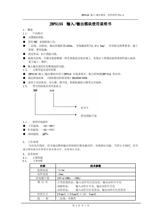
4、 尺寸、重量 4.1、 外形及安装尺寸
JBF5155 输入/输出模块 使用说明书V1.3
5、 安装、调试 5.1、 安装程序、方法及注意事项 ● JBF5155 模块采用明装方式;
● 布线施工后,通过预埋盒或使用膨胀螺栓将底座固定在墙上(使用M4 螺钉),安装孔距为65mm。 ● 探测总线采用2×1.0-1.5mm²导线。 ● 将端子3、2接在控制器对应的专线输出端子 SL+、SL- 上 。 将 9 和 6 ( 1 , 7 ) 接 在 被 控 设 备 启
CO输出24V 电压,2秒后停止输出。
5.2.1 “持续输出”时的接线图
第2页共4页
JBF5155 输入/输出模块 使用说明书V1.3
持续输出
SL-
SL+
GNDSL- SL+
JBF5155
GNDGND AS C1 CO
10K 3K
J1
AS和GND之间接无源触点作为应答信号。
继电器线圈阻抗要求:300-线端子 接线
将无源触点复位
备注
7、 保养、维修 7.1、 日常维护、保养、校准 7.2、 长期停放时的维护、保养
定期进行动作试验,建议每半年一次。 产品执行标准:《消防联动控制系统》 GB16806-2006
第4页共4页
5.2、 输出方式设置及接线方法 ● 该模块的输出方式可以通过更改控制器“设置多线登记及故障检测”菜单下的“输出状态”进
行设置,其中“0”代表持续输出,“1”代表单次输出。
● 持续输出时仅C1 端子输出,“启动”状态输出24V 电压,“停止”状态不输出。 ● 单次输出时 C1,C0 都有输出信号,“启动”时 C1 输出24V 电压,2秒后停止输出;“停止”时
XMC4500自动化输入输出芯片模块说明书

XMC4500 Satellite-kit: Automation I/O Kit Part Number: KIT_XMC4X_AUT_ISO_001Features∙Connection to CPU board via ACT Satellite Connector∙ISOFACE OUT, up to 8 channels∙ISOFACE IN, up to 8 channels∙I2C based IO expander up to 8 channels∙Single side assembly of all parts∙ 2 LEDs indicating power (3.3 Volt, 5 Volt)∙Power supply:-Power jack for external 24V supply-From CPU Board via ACT Satellite ConnectorPLEASE SEE THE FOLLOWING PAGES FOR USERS MANUALHexagon Application Kit For XMC4000 FamilyAUT_ISO-V1Automation I/O CardBoard User's Manual Revision 1.0, 2012-02-28Edition 2012-02-28Published byInfineon Technologies AG81726 Munich, Germany© 2012 Infineon Technologies AGAll Rights Reserved.Legal DisclaimerThe information given in this document shall in no event be regarded as a guarantee of conditions or characteristics. With respect to any examples or hints given herein, any typical values stated herein and/or any information regarding the application of the device, Infineon Technologies hereby disclaims any and all warranties and liabilities of any kind, including without limitation, warranties of non-infringement of intellectual property rights of any third party.InformationFor further information on technology, delivery terms and conditions and prices, please contact the nearest Infineon Technologies Office ().WarningsDue to technical requirements, components may contain dangerous substances. For information on the types in question, please contact the nearest Infineon Technologies Office.Infineon Technologies components may be used in life-support devices or systems only with the express written approval of Infineon Technologies, if a failure of such components can reasonably be expected to cause the failure of that life-support device or system or to affect the safety or effectiveness of that device or system. Life support devices or systems are intended to be implanted in the human body or to support and/or maintain and sustain and/or protect human life. If they fail, it is reasonable to assume that the health of the user or otherTrademarks of Infineon Technologies AGAURIX™, C166™, CanPAK™, CIPOS™, CIPURSE™, EconoPACK™, CoolMOS™, CoolSET™, CORECONTROL™, CROSSAVE™, DAVE™, EasyPIM™, EconoBRIDGE™, EconoDUAL™, EconoPIM™, EiceDRIVER™, eupec™, FCOS™, HITFET™, HybridPACK™, I²RF™, ISOFACE™, IsoPACK™, MIPAQ™, ModSTACK™,my-d™, NovalithIC™, OptiMOS™, ORIGA™, PRIMARION™, PrimePACK™, PrimeSTACK™, PRO-SIL™, PROFET™, RASIC™, ReverSave™, SatRIC™, SIEGET™, SINDRION™, SIPMOS™, SmartLEWIS™, SOLID FLASH™, TEMPFET™, thinQ!™, TRENCHSTOP™, TriCore™.Other TrademarksAdvance Design System™ (ADS) of Agilent Technologies, AMBA™, ARM™, MULTI-ICE™, KEIL™, PRIMECELL™, REALVIEW™, THUMB™, µVision™ of ARM Limited, UK. AUTOSAR™ is licensed by AUTOSAR development partnership. Bluetooth™ of Bluetooth SIG Inc. CAT-iq™ of DECT Foru m. COLOSSUS™, FirstGPS™ of Trimble Navigation Ltd. EMV™ of EMVCo, LLC (Visa Holdings Inc.). EPCOS™ of Epcos AG. FLEXGO™ of Microsoft Corporation. FlexRay™ is licensed by FlexRay Consortium. HYPERTERMINAL™ of Hilgraeve Incorporated. IEC™ of Commission Electrotechnique Internationale. IrDA™ of Infrared Data Association Corporation. ISO™ of INTERNATIONAL ORGANIZATION FOR STANDARDIZATION. MATLAB™ of MathWorks, Inc. MAXIM™ of Maxim Integrated Products, Inc. MICROTEC™, NUCLEUS™ of Mentor Graphics Corporation. Mifare™ of NXP. MIPI™ of MIPI Alliance, Inc. MIPS™ of MIPS Technologies, Inc., USA. muRata™ of MURATA MANUFACTURING CO., MICROWAVE OFFICE™ (MWO) of Applied Wave Research Inc., OmniVision™ of OmniVision Technologies, Inc. Openwave™ Openwave Systems Inc. RED HAT™ Red Hat, Inc. RFMD™ RF Micro Devices, Inc. SIRIUS™ of Sirius Satellite Radio Inc. SOLARIS™ of Sun Microsystems, Inc. SPANSION™ of Spansion LLC Ltd. Symbian™ of Symbian Software Limited. TAIYO YUDEN™ of Taiyo Yuden Co. TEAKLITE™ of CEVA, Inc. TEKTRONIX™ of Tektronix Inc. TOKO™ of TOKO KABUSHIKI KAISHA TA. UNIX™ of X/Open Company Limited. VERILOG™, PALLADIUM™ of Cadence Design Systems, Inc. VLYNQ™ of Texas Instruments Incorporated. VXWORKS™, WIND RIVER™ of WIND RIVER SYSTEMS, INC. ZETEX™ of Diodes Zetex Limited.Last Trademarks Update 2011-02-24Table of ContentsTable of Contents1Overview (7)1.1Key Features (7)1.2Block Diagram (8)2Hardware Description (8)2.1ISOFACE OUT (9)2.2ISOFACE IN (9)2.3IO Expander (10)2.4Power (11)2.5Satellite Connector (12)3Production Data (13)3.1Schematics (13)3.2Layout and Geometry (16)3.3Bill of Material (17)List of FiguresFigure 1Automation I/O Card (AUT_ISO-V1) (8)Figure 2Automation I/O Card Interfaces (8)Figure 3Power Circuit (11)Figure 4ACT Satellite Connector (12)Figure 5Satellite Connector Type ACT (12)Figure 6Satellite Connector, IO Expander, Power (14)Figure 7ISOFACE (15)Figure 8Automation I/O Card Layout (16)List of TablesTable 1ISOFACE OUT Connector Pinout (9)Table 2ISOFACE OUT signal connection to the Satellite Connector (9)Table 3ISOFACE IN Connector Pinout (9)Table 4ISOFACE IN signal connection to the Satellite Connector (10)Table 5GPIO channel LED/SMD pad mapping (10)Table 6IO Expander I2C signal connection to the Satellite Connector (10)Table 7Power LED’s (11)Table 8PowerScale Jumper (11)Table 9Automation I/O Card BOM (17)OverviewIntroductionThis document describes the features and hardware details of the Automation I/O Card (AUT_ISO-V1) designed to work with Infineon’s XMC4500 CPU board. This board is part of Infineon’s Hexagon Application Kits.1 OverviewThe AUT_ISO-V1 board is an application expansion satellite card of the Hexagon Application Kits. The satellite card along with a CPU board (e.g. CPU_45A-V2 board) demonstrates ISOFACE capabilities together with XMC4500. The focus is safe operation under evaluation conditions. The satellite card is not cost optimized and cannot be seen as reference design.1.1 Key FeaturesThe AUT_ISO-V1 satellite card is equipped with following featuresConnection to CPU board (e.g. CPU_45A-V2) via satellite connector ACTISOFACE OUT, up to 8 channelsISOFACE IN, up to 8 channelsI2C based IO expander up to 8 channelsPower supplyo Powerjack for external 24 V supplyo From CPU board via ACT satellite connector1.2Block DiagramFigure 1 shows the block diagram of the AUT_ISO-V1 satellite card. There are following building blocks:Figure 1Automation I/O Card (AUT_ISO-V1)2 Hardware DescriptionThe following sections give a detailed description of the hardware and how it can be used.Figure 2 Automation I/O Card InterfacesISOFACE OUT (ISO1H812G)ISOFACE IN (ISO1I811T)Power 3.3 V (IFX1763SJV33)ISOFACE IN ConnectorACT Satellite ConnectorPower Jack24 V2.1 ISOFACE OUTISOFACE output device used in AUT_ISO-V1 satellite card is ISO1H812G. It is supplied by VDD3.3 on the CPU side and VDD24 for the ISOFACE OUT side. VDD24 and GNDISO can to be connected either by X300 or by X240(24 V external power jack). This is the same net that supplies the DC/DC converter. VDD24 is +24 Vdc (referred to GNDISO)Table 1 below gives the signal details of ISOFACE OUT connector.Table 12 below gives the details of SPI signal connection to the satellite connector.2.2 ISOFACE INISOFACE input device used in AUT_ISO-V1 satellite card is ISO1I811T. It is supplied by 3.3 V on the CPU side and VBB (24V) for the ISOFACE IN side. VBB and GNDBB need a separate connection to 24 V external power source through connector X320.Resistor R337 is used on board for setting input type to IEC61131-2 Type 1.Resistors R326 and R327 sets the frequency of ISOFACE IN to 100 kHz (default).Table 3 gives the details of ISOFACE IN connector pin mapping.Table 3 ISOFACE IN Connector PinoutISOFACE IN shares the same SPI lines with ISOFACE OUT except the chip select as shown in Table 4.2.3 IO ExpanderThe AUT_ISO-V1 satellite card supports GPIO expansion though I2C IO-Expander on board (U230). The I2C Address for IO expander device is 0x1001000X. The satellite card supports 8 such GPIO’s. All t he GPIO’s are connected to LEDs (V230-V237) and SMD-Pads (TP230 – TP237). The Table 5 gives the GPIO channel and corresponding LED/PAD mapping.Table 6 shows the connection of the IO Expander device to the ACT satellite connector.2.4 PowerThe AUT_ISO-V1 satellite card can be supplied by an external power supply (24 V / 1 A) to be connected to the power jack X240 or by a 5 V supply via the 80-pin ACT satellite connector. An external power supply is necessary only in case the current coming via the ACT satellite connector is not sufficient.A DC-DC converter on board (U240) steps down the input voltage from the power jack X240 to 5 V (VDD5). The input voltage can be in the range from 12 V to 24 V. An on board linear voltage regulator is generating a 3.3 V (VDD3.3) power supply out of the VDD5.Figure 3 Power CircuitA Diode V242 protects the reverse flow of current to an external source. Therefore a simultaneous power supply of the satellite boards via both the power jack and the satellite connector with not harm.LED V210 indicates the presence of 5 V power and LED V211 indicates the presence of 3.3 V power.Table 7 Power LED’sThe AUT_ISO-V1 satellite card supports a PowerScale probe for power measurement purpose.Table 8 PowerScale Jumper2.5 Satellite ConnectorThe satellite connector of the AUT_ISO-V1 satellite card interfaces it’s the signals to a CPU board e.g. CPU_45A-V2. Take care to connect the ACT satellite card always to the corresponding ACT satellite connector of the CPU board only.Figure 4 ACT Satellite ConnectorThe signal mapping of the ACT satellite connector and correponding CPU function are provided in figure 6Figure 5 Satellite Connector Type ACT3 Production Data3.1 SchematicsThis chapter contains the schematics for the Automation I/O Card:Satellite Connector, IO Expander, PowerISOFACEFigure 6 Satellite Connector, IO Expander, PowerFigure 7 ISOFACE3.2 Layout and GeometryFigure 8 Automation I/O Card Layout3.3 Bill of MaterialTable 9 Automation I/O Card BOMTable 9 Automation I/O Card BOMw w w.i n f i n e o n.c o m。
海湾消防GST-LD-8303输入-输出模块安装说明书[1]
![海湾消防GST-LD-8303输入-输出模块安装说明书[1]](https://img.taocdn.com/s3/m/6931ba06de80d4d8d15a4f60.png)
输入1 输出1
GST-LD-8303 输入/输出模块
输入2 输出2
图 1 外形示意图
五、 安装与布线
警告: 接 � 安装设备之前,请切断回路的电源并确认全部底壳已安装牢靠且每一个底壳的连 安装设备之前,请切断回路的电源并确认全部底壳已安装牢靠且每一个底壳的连接 线准确无误。 “常开检线 ”状态输入,模块输入线末端(远离模块端) 必 � 模块输入端如果设置为 模块输入端如果设置为“ 常开检线” 状态输入,模块输入线末端(远离模块端)必 Ω的终端电阻;模块输入端如果设置为 “常闭检线 ”状态输入模块输入线 须并联一个 4.7k 4.7kΩ 的终端电阻;模块输入端如果设置为“ 常闭检线” Ω的终端电阻(具体接线方法见应用方法) 。 末端(远离模块端)必须串联一个 4.7k 4.7kΩ ,有源输出端应并联一个 4.7k Ω的终端电阻,并串联一个 IN400 7 � 模块为有源输出时 模块为有源输出时, 4.7kΩ IN4007 二极管(具体接线方法见应用方法) 。 1. 安装前应首先检查外壳是否完好无损,标识是否齐全。 2. 模块采用明装方式,底壳与模块间采用插接式结构安装,安装时只需拔下模块,从底壳 的进线孔中穿入电缆并接在相应的端子上,再插好模块即可安装好模块。 3. 模块采用线管预埋安装, 将底盒安装在 86H50 型预埋盒上, 安装孔距为 60mm(参见图 3), 安装示意图如图 2 所示。
1. 模块与 GST-LD-8302A 模块组合连接的方法如图 4 所示。
+24V G Z1 Z2
D1
D2
Z1
Z2
GST-LD-8303
I1 G I2 G S1+ S1S2+ S2-
4.7kΩ 4.7kΩ 4.7kΩ 1N4007
GST-LD-8301输入输出模块安装使用说明书-海湾
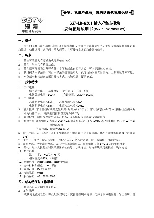
安装、使用产品前,请阅读安装使用说明书GST-LD-8301输入/输出模块安装使用说明书(Ver.1.02,2008.02)一、概述GST-LD-8301输入/输出模块(以下简称模块),主要用于连接需要火灾报警控制器控制的消防联动设备,如排烟阀、送风阀、防火阀等,并可接收设备的动作回答信号。
二、特点1.输出可设置为有源输出或无源输出方式。
2.输入、输出具有检线功能。
3.输入端可现场设为常开检线、常闭检线或自回答方式,可与无源触点连接。
4.地址码为电子编码,可由电子编码器事先写入,也可由控制器直接更改,工程调试简便可靠。
5.电路部分和接线底壳采用插接方式,接触可靠、便于施工。
三、技术特性1.工作电压:信号总线电压:总线24V 允许范围: 16V~28V电源总线电压:DC24V 允许范围:DC20V~DC28V2.工作电流:总线监视电流≤1mA 总线启动电流≤3mA电源监视电流≤5mA 电源启动电流≤20mA3.输入检线:常开检线时线路发生断路(短路为动作信号)、常闭检线输入时输入线路发生短路(断路为动作信号),模块将向控制器发送故障信号4.输出检线:输出线路发生短路、断路,模块将向控制器发送故障信号5.输出容量:无源输出:容量为DC24V/2A,正常时触点阻值为100kΩ,启动时闭合,适用于12V~48V直流或交流有源输出:容量为DC24V/1A6.输出控制方式:脉冲、电平(继电器常开触点输出或有源输出,脉冲启动时继电器吸合时间为10s)7.指示灯:红色(输入指示灯:巡检时闪亮,动作时常亮;输出指示灯:启动时常亮)8.编码方式:电子编码方式,占用一个总线编码点,编码范围可在1~242之间任意设定9.线制:与火灾报警控制器采用无极性信号二总线连接,与电源线采用无极性二线制连接10.使用环境:温度: -10℃~+55℃相对湿度≤95%,不凝露11.外形尺寸:86mm×86mm×43mm(带底壳)12.壳体材料和颜色:ABS,瓷白13.重量:约145g(带底壳)14.安装孔距:60mm15.执行标准:GB 16806-2006四、结构特征与工作原理1.模块外形示意图如图1所示。
- 1、下载文档前请自行甄别文档内容的完整性,平台不提供额外的编辑、内容补充、找答案等附加服务。
- 2、"仅部分预览"的文档,不可在线预览部分如存在完整性等问题,可反馈申请退款(可完整预览的文档不适用该条件!)。
- 3、如文档侵犯您的权益,请联系客服反馈,我们会尽快为您处理(人工客服工作时间:9:00-18:30)。
• 1.首先需要熟悉I/O模块的接法 打开控制柜,可以看到门上的KEBA控制器, 有两个I/O模块:DM272/A • 通常情况下,现场客户只允许使用第二个 DM272/A。见下图
控制按钮的编制
输入接线图:
1为电源,19为24V,20为0V; 2 为输出,IODout(8-15); 3 为输入,IODin (8-15);
右开关
19
左开关 DI2 10
图中的10;12;分别为 示教器中的输入变量的IODin 点;
DI4
12控制按钮的编制• 2.在示教器上建立2个输入变量,对应到模 块上的10;12;(注意:全局中-新建-输 入输出-DIN)
控制按钮的编制
a.点击下 看到如下界面: ,选择变量监控。可以
控制按钮的编制
b.选择全局
控制按钮的编制
• c.建立变量
控制按钮的编制
控制按钮的编制
• 在输入输出模块中选择DIN,如下图
控制按钮的编制
• 修改名称,确认。
zuoxinhao
控制按钮的编制
• 在变量界面中,点开全局的“+”,找到刚刚 建立的“zuobianxinhao”变量。
zuoxinhao:DIN
控制按钮的编制
• 在后面选择 ;输入10;
zuoxinhao:DIN
控制按钮的编制
10
zuoxinhao:DIN
控制按钮的编制
• 建立完成后,就下图;
zuoxinhao:DIN
控制按钮的编制
• 再按照上述步骤,将youxinhao的变量建好。