220C说明书-V1001.0
220C控制器用户手册

CNC-220C绕线机控制器用户手册v1.0适用于F2000/n01 n02 n03……系列软件版本目录一.前言二.主要特性三.面板说明四.用户设定五.基本功能六.AUX I/O备用接口七.特种功能定制八.常用位移单位九.故障与排除十.硬件说明注意事项:控制器机箱金属壳体务必可靠接地!装配前,务必关闭电源!配线焊接前,断开与控制器相关的所有连接线,并使用防静电烙铁!不可将异物如机箱加工飞溅的铁屑等置入电路板,造成短路损坏控制器!不可故意伸手触摸电路板元件,防止人体静电损坏控制器!为了防止人身安全,控制器断电后在内部驱动板上相关指示灯没有熄灭之前,勿用手触摸电路板或元器件!定期清除圈数感应器和原点感应器上的粉尘,必要时予以更换!定期对控制器内部电路板,干燥除尘、紧固螺丝及连接线等的保养!一.前言CNN-220C是本公司最新推出的第三代绕线机控制器。
以CNC-220B控制器软件思想为基础,功能已渗透绕线行业各种类型使用场合,属于绕线机的标准配备,完全取代原有的CNC-220S/B。
该控制器采用16位大规模集成化的运动控制专用芯片,运算速度快、电路简洁体积小、全新硬件结构其抗干扰能力更强,并保留本公司原有机型的功能延续性及完全相同的操作方式。
随着软件和硬件系统的不断完善和创新,在绕线行业内已经形成一套完整的功能标准和全新的绕线理论。
本控制器简单易学。
原有广大用户不需要重新学习本控制器的具体操作方法就能短时间内很快掌握其功能要点,并能熟练使用。
CNC-220C按照绕线轴驱动信号及对象,暂定为一种机型:绕线轴信号排线轴机型信号驱动对象0~10V直流电压220CH/L高低速电平1.单/三相交流变频器2.外部直流无刷驱动器兼容以下两种负载方式:1.直接驱动两相2A步进马达2.外接步进马达驱动器二.主要特点z16位高速指令芯片系统支持行业功能和传统操作习惯z排线轴位移单位10倍选择z排线轴传动比和螺杆节距不受限制z高精度排线同步监测系统z外置步进驱动器信号输出口z绕线轴内置大功率直流无刷驱动器z绕线轴外置交流变频器或直流无刷驱动器z排线轴外置两相步进驱动器z增强型疏绕线功能z完善的自我检测功能注意事项:本控制器正常工作环境温度10℃~40℃上电复归或按面板复归键,在圈数窗口显示F2000、F3000、C-200等品牌字样;在产量窗口显示FXXXX、n01、n02等字样表示软件升级和功能属性;本控制器内部电路板上标注有321、221等厂家生产信息。
Axicom IM标准双形C双接触器电容器220VDC接触电压等参数说明书
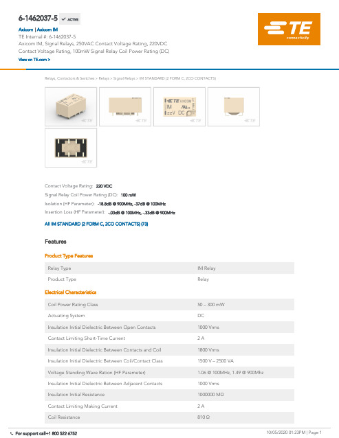
6-1462037-5Axicom IM, Signal Relays, 250VAC Contact Voltage Rating, 220VDC Contact Voltage Rating, 100mW Signal Relay Coil Power Rating (DC)Relays, Contactors & Switches > Relays > Signal Relays >IM STANDARD (2 FORM C, 2CO CONTACTS)Insertion Loss (HF Parameter):-.03dB @ 100MHz, -.33dB @ 900MHzIsolation (HF Parameter):-18.8dB @ 900MHz, -37dB @ 100MHzSignal Relay Coil Power Rating (DC):100 mWContact Voltage Rating:220 VDCAll IM STANDARD (2 FORM C, 2CO CONTACTS) (73)FeaturesProduct Type Features Relay Type IM Relay Product TypeRelayElectrical Characteristics Coil Power Rating Class 50 – 300 mW Actuating SystemDC Insulation Initial Dielectric Between Open Contacts 1000 Vrms Contact Limiting Short-Time Current2 A Insulation Initial Dielectric Between Contacts and Coil 1800 Vrms Insulation Initial Dielectric Between Coil/Contact Class 1500 V – 2500 VAVoltage Standing Wave Ration (HF Parameter) 1.06 @ 100MHz, 1.49 @ 900Mhz Insulation Initial Dielectric Between Adjacent Contacts 1000 Vrms Insulation Initial Resistance 1000000 MΩContact Limiting Making Current 2 A Coil Resistance810 Ω 6-1462037-5 ACTIVEAxicom TE Internal #:6-1462037-5Axicom IM, Signal Relays, 250VAC Contact Voltage Rating, 220VDC Contact Voltage Rating, 100mW Signal Relay Coil Power Rating (DC)View on >Axicom IM|Contact Limiting Continuous Current 2 ACoil Type BistableContact Limiting Breaking Current 2 AContact Switching Load (Min).1mA @ .0001VContact Voltage Rating220 VDCSignal Relay Coil Power Rating (DC)100 mWSignal Relay Coil Voltage Rating9 VDCSignal Relay Contact Switching Voltage (Max)220 VDCSignal Relay Coil Magnetic System Bistable, 1 CoilSignal CharacteristicsIsolation (HF Parameter)-18.8dB @ 900MHz, -37dB @ 100MHz Insertion Loss (HF Parameter)-.03dB @ 100MHz, -.33dB @ 900MHz Body FeaturesInsulation Special Features2500V Initial Surge Withstand Voltagebetween Contacts & CoilWeight.75 g[.026 oz]Contact FeaturesContact Plating Material GoldContact Current Class0 – 2 AContact Special Features Bifurcated/Twin ContactsSignal Relay Terminal Type PCB-SMTSignal Relay Contact Current Rating 2 ASignal Relay Contact Arrangement 2 Form C (2 CO)Contact Material PdRu+AuContact Number of Poles2Termination FeaturesTermination Type Surface MountMechanical AttachmentSignal Relay Mounting Type Printed Circuit BoardDimensionsWidth Class (Mechanical)0 – 6 mmWidth 6 mm[.222 in]Height 5.65 mm[.221 in]Length Class (Mechanical)0 – 10 mmLength10 mm[.393 in]Height Class (Mechanical)0 – 6 mmDimensions (L x W x H) (Approximate)10 x 6 x 5.65 mm[.393 x .236 x .222 in] Usage ConditionsEnvironmental Ambient Temperature (Max)85 °C[185 °F]Environmental Ambient Temperature Class70 – 85°CEnvironmental Category of Protection RTVOperating Temperature Range-40 – 85 °C, -40 – 85 °COperation/ApplicationPerformance Type StandardPackaging FeaturesPackaging Method ReelOtherAdditional Features J LegProduct ComplianceFor compliance documentation, visit the product page on >EU RoHS Directive 2011/65/EU CompliantEU ELV Directive 2000/53/EC CompliantChina RoHS 2 Directive MIIT Order No 32, 2016No Restricted Materials Above ThresholdEU REACH Regulation (EC) No. 1907/2006Current ECHA Candidate List: JUN 2020(209)Candidate List Declared Against: JUN 2020(209)Does not contain REACH SVHCHalogen Content BFR/CFR/PVC Free, but Br/Cl >900 ppm inother sources.Solder Process Capability Reflow solder capable to 260°CProduct Compliance DisclaimerThis information is provided based on reasonable inquiry of our suppliers and represents our current actual knowledgebased on the information they provided. This information is subject to change. The part numbers that TE has identified asEU RoHS compliant have a maximum concentration of 0.1% by weight in homogenous materials for lead, hexavalentchromium, mercury, PBB, PBDE, DBP, BBP, DEHP, DIBP, and 0.01% for cadmium, or qualify for an exemption to theselimits as defined in the Annexes of Directive 2011/65/EU (RoHS2). Finished electrical and electronic equipment productswill be CE marked as required by Directive 2011/65/EU. Components may not be CE marked. Additionally, the part numbers that TE has identified as EU ELV compliant have a maximum concentration of 0.1% by weight in homogenous materials for lead, hexavalent chromium, and mercury, and 0.01% for cadmium, or qualify for an exemption to these limits as defined in the Annexes of Directive 2000/53/EC (ELV). Regarding the REACH Regulation, the information TE provides on SVHC in articles for this part number is based on the latest European Chemicals Agency (ECHA) ‘Guidance onrequirements for substances in articles’ posted at this URL: https://echa.europa.eu/guidance-documents/guidance-on-reachTE Model / Part #640417-2BLADE REC 250 18-14AWG TPBRTE Model / Part #2129261-1PLUG ASSY 0.6mm CHAMP DOCKINGTE Model / Part #2129260-2REC ASSY 0.6mm CHAMP DOCKING CTE Model / Part #60279-2FASTON 250 14-18AWG TPBRTE Model / Part #5447647-3PLUG, SMA, HEX CRIMP COMMTE Model / Part #5-1634500-0BNC Str Plg Hex 50Ohm Nickel Plated RG17TE Model / Part #6-1462037-0IM STANDARD (2 FORM C, 2CO CONTACTS)TE Model / Part #1-2199119-5M.2 CONNECTORSSignal Relays(122)RJ45 Connectors(2) TE Model / Part #CAT-AX41-IM11B IM STANDARD (2 FORM C, 2CO CONTACTS)Compatible PartsAlso in the Series Axicom IMCustomers Also BoughtTE Model / Part #285750300844A0111-26-0DocumentsProduct DrawingsIM45JR=IM RELAY 100 MW 9 V BISEnglishIM45JR=IM RELAY 100 MW 9 V BISEnglishCAD Files3D PDF3DCustomer View ModelENG_CVM_CVM_1462037-3_A.2d_dxf.zipEnglishCustomer View ModelENG_CVM_CVM_1462037-3_A.3d_igs.zipEnglishCustomer View ModelENG_CVM_CVM_1462037-3_A.3d_stp.zipEnglishTerms and ConditionsBy downloading the CAD file I accept and agree to the of use.Datasheets & Catalog PagesAxicom Signal and High Frequency Relays (RF Switches) APPLICATION NOTE #2 EnglishLighting Relays GuideEnglishIM Relay DatasheetEnglishIndustrial Relays Quick Reference GuideEnglishProduct SpecificationsDefinitions RelaysEnglish。
中国美德电器 PS200VL 220VL 224VL 三合一烹饪机产品说明书

P S 200V L , P S 220V L ,&P S 224V LPS200VL/220VL/224VL Parts Gas (AGA[CSA])P/N 38539Rev. B V2 1/00Middleby Cook ing Systems Group 1400 Toastmaster Drive Elgin, IL 60120 (847)741-3300 FAX (847)741-4406PARTS MANUAL© 2000 Middleby Marshall, Inc.is a registered trademark of Middleby Marshall, Inc. All rights reserved.PS200VL/220VL/224VL Gas OvensModels: PS200VL PS220VLPS224VLfor domestic and standard export ovensTABLE OF CONTENTSSection Page I.Key Spare Parts Kit (3)II.Installation Kit (4)III.Oven Base/Legs/Casters Kit (5)IV.Oven Panels, Windows, and Legs (6)V.Cool Front (8)VI.Blower, Shrouds and Vents (10)VII.Machinery Compartment (12)VIII.Control Panel (14)IX.External Transformer - Export Ovens Only (16)X.Gas Burner System (18)X I.Conveyor Assembly - Single Conveyor (20)X II.Conveyor Assembly - Split Belt Conveyor (22)NOTE: Throughout this Parts Manual, the following abbreviations are used: A/R = Quantity As RequiredN/A = Does Not ApplyP S 200V L , P S 220V L ,& P S 224V LI. KEY SPARE PARTS KITITEMPART NO.QTY.DESCRIPTION127381-00661BLOWER/FAN MOTOR227384-00111CON VEYOR DRIVE MOTOR342810-01331CON VEYOR SPEED CON TROLLER 4339851THERMOCOUPLE522450-02302CON VEYOR DRIVE MOTOR BRUSHES 628091-00171SOLEN OID VALVE727170-00111BURN ER MOTOR/BLOWER ASSEMBLY 842810-01141IGN ITION MODULE927170-02631CON VEYOR CON TROL PICKUP 10349821HIGH LIMIT CON TROLII. INSTALLATION KITITEMPART NO.QTY.DESCRIPTIONPS200VLPS220VLPS224VLSgl ovenDbl oven122361-000122361-000122361-000112GAS HOSE, FLEXIBLE223115-001023115-001023115-001012GAS SHUTOFF VALVE, 3/4 335000-110335900-037035900-044212CONVEYOR END STOP 435900-014835900-037635900-014812CONVEYOR REAR STOP536019360193601912OWNER S OPERATING MANUAL 610020401002040100204012SERVICE AGEN CY DIRECTORY7A 42400-008949400-019742400-009012MASTER LINKS KIT - SINGLE BELT OVENS 7B 42400-00893659642400-058924MASTER LINKS KIT - SPLIT BELT OVENS 821392-000521392-000521392-000512SCREW EYE, LAG, 3/4 ID x 2-1/23467A,7BP S 200V L , P S 220V L ,& P S 224V LIII. OVEN BASE/LEGS/CASTERS KITITEMPART NO.QTY.DESCRIPTIONPS200VLPS220VLPS224VLSgl ovenDbl oven130427308063080711BASE PAD, PAINTED23042630426304264--LEG, 15 (381mm), PAIN TED - SINGLE OVENS ONLY 322290-000922290-000922290-000922SWIVEL CASTER w/LOCKING BRAKE 422290-001022290-001022290-001022SWIVEL CASTER 522037322037322037332163/8-16 x 1 HEX BOLT 621416-000121416-000121416-000132163/8 FLAT WASHER 721422-000121422-000121422-000132163/8 SPLIT WASHER821256-000821256-000821256-00084410-32 x 3/8 RH SCREWS FOR TOP 922450-022822450-022822450-022811RESTRAINT CABLE ASSEMBLY1037900-004137900-004137900-0041--1FLUE OFFSET - DOUBLE OVENS ONLY 1137900-004237900-004237900-0042--1FLUE EXTENSION - DOUBLE OVENS ONLY --35900-001135900-034735900-041311OVEN TOP124Middleby Cooking Systems Group 1400 Toastmaster Drive Elgin, IL 60120 USA (847)741-3300 FAX (847)741-440624-Hour Service Hotline: 1-(800)-238-8444 WARNINGImproper installation, adjustment, alteration, service or maintenance can cause property damage, injury or death. Read the installation,operating and maintenance instructions thoroughly before installing or servicing this equipment.NOTICE During the warranty period, ALL parts replacement and servicing should be performed by your Middleby Marshall Authorized Service Agent. Service that is performed by parties other than your Middleby Marshall Authorized Service Agent may void your warranty.NOTICE Using any parts other than genuine Middleby Marshall factory manufactured parts relieves the manufacturer of all warranty and liability.NOTICE Middleby Marshall reserves the right to change specifications at any time.。
CAV22010-10说明书
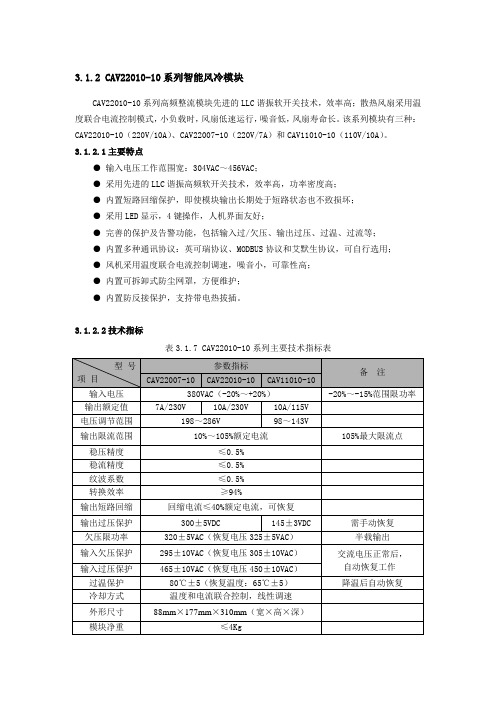
3.1.2 CAV22010-10系列智能风冷模块CAV22010-10系列高频整流模块先进的LLC谐振软开关技术,效率高;散热风扇采用温度联合电流控制模式,小负载时,风扇低速运行,噪音低,风扇寿命长。
该系列模块有三种:CAV22010-10(220V/10A)、CAV22007-10(220V/7A)和CAV11010-10(110V/10A)。
3.1.2.1主要特点●输入电压工作范围宽:304VAC~456VAC;●采用先进的LLC谐振高频软开关技术,效率高,功率密度高;●内置短路回缩保护,即使模块输出长期处于短路状态也不致损坏;●采用LED显示,4键操作,人机界面友好;●完善的保护及告警功能,包括输入过/欠压、输出过压、过温、过流等;●内置多种通讯协议:英可瑞协议、MODBUS协议和艾默生协议,可自行选用;●风机采用温度联合电流控制调速,噪音小,可靠性高;●内置可拆卸式防尘网罩,方便维护;●内置防反接保护,支持带电热拔插。
3.1.2.2技术指标表3.1.7 CAV22010-10系列主要技术指标表3.1.2.3外形结构与接口1、外形结构图3.1.7模块外形图2、输入输出的接口图3.1.8航空组件定义图表3.1.8 整流模块插座定义表注意:1、为了保障安全,请确保将交流输入中的保护地PE端与大地正确连接;2、为了保障系统的可靠性,每个模块的三相交流输入必须单独配置进线空开。
3.1.2.4操作说明连接好电源和负载,将模块正确插入托架,上电后等待5秒钟左右,模块启动完成,在无故障的情况下,面板上仅绿色工作指示灯在点亮,表示模块处于正常的工作状态。
模块采用LED数码管显示,有3个LED指示灯,各灯的工作定义如表3.1.9所示:表3.1.9 工作指示灯定义表模块有4个操作按键,定义如表3.1.10所示:表3.1.10 按键定义表1、工作状态参数查询LED显示当前的输出电压,通过按动▲或▼,可以查看模块当前的其他工作参数。
2201L 触摸显示器使用手册说明书
使用者手册2201L 觸摸顯示器版權所有© 2011 T yco Electronics。
保留所有權利。
未經 Tyco Electronics 的書面許可,不得以任何形式或方法(包括但不限於電子、磁性、光學、化學方法或手册等)複製、傳輸或改編本出版物的任何部分,不得將其儲存到擷取系統,不得將其翻譯成任何語言或電腦語言。
免責告示本文件中的訊息有可能在未通知的情况下進行變更。
Tyco Electronics 對本出版物的內容不提供任何形式的陳述或擔保,並且特別宣告拒絕對有特定目的適銷性或適用性提供任何默示擔保。
Tyco Electronics 保留對本出版物進行修訂並對其內容不斷進行變更,而不將這樣的修訂和變更通知任何人的權利。
商標告示Elo TouchSystems、IntelliTouch、iTouch、Tyco Electronics 和 TE(標誌)是 Tyco Electronics 集團公司及其許可方的商標。
Windows 為 Microsoft 集團公司的商標。
本文件中出現的其他產品名稱可能是其各自公司的商標或注册商標。
Tyco Electronics 對除自有商標以外的其他商標不享有任何權益。
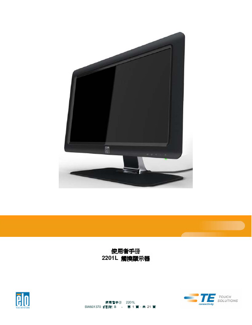
目錄第 1 章 – 簡介 (4)第 2 章 – 安裝 (5)第 3 章 – 安裝 (9)第 4 章 – 操作 (10)第 5 章 – 技術支援 (14)第 6 章 – 安全與維護 (15)第 7 章 – 法規訊息 (16)第 8 章 – 擔保訊息 (19)第 1 章 – 簡介產品說明新的觸摸顯示器集 Elo TouchSystems 的可靠效能和觸摸技術與顯示屏設計領域的最新進展於一身。
這種功能組合可在使用者與觸摸顯示屏之間提供自然的訊息流動。
此觸摸顯示器帶有一個 24 位彩色有源矩陣薄膜晶體管 LCD 面板,提供了優异的顯示效能。
其全 HD 解析度 1920x1080 適合顯示圖形和影像。
品牌MA220型号400A AC DC夹形电流表产品用户手册说明书
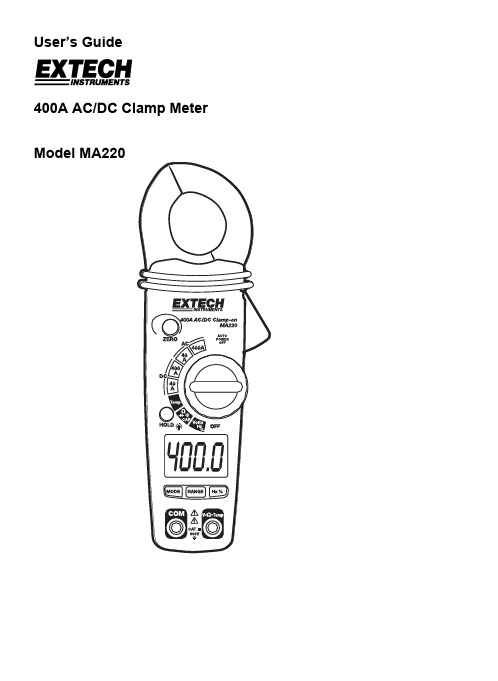
User’s Guide400A AC/DC Clamp MeterModel MA220MA220 V1.3 10/062IntroductionThank you for selecting the Extech MA200 AC/DC Clamp Meter. This meter measures AC/DC Current, AC/DC Voltage, Resistance, Capacitance, Frequency, Duty Cycle,Temperature, Diode Test, and Continuity. This professional meter, with proper care, will provide years of safe reliable service.SafetyInternational Safety SymbolsThis symbol, adjacent to another symbol or terminal, indicates the user must refer to the manual for further information.This symbol, adjacent to a terminal, indicates that, under normal use, hazardous voltages may be presentDouble insulationA UL mark does not indicate that this product has been evaluated for the accuracy of its readings.SAFETY NOTES• Do not exceed the maximum allowable input range of any function • Do not apply voltage to meter when resistance function is selected. • Set the function switch OFF when the meter is not in use.• Remove the battery if meter is to be stored for longer than 60 days.WARNINGS• Set function switch to the appropriate position before measuring. • When measuring volts do not switch to current/resistance modes. • Do not measure current on a circuit whose voltage exceeds 240V.• When changing ranges using the selector switch always disconnect the test leadsfrom the circuit under test. • Do not exceed the maximum rated input limits.OVERVOLTAGE CATEGORY IIIThis meter meets the IEC 610-1-95 standard for OVERVOLTAGE CATEGORY III. Cat III meters are protected against overvoltage transients in fixed installation at the distribution level. Examples include switches in the fixed installation and some equipment for industrial use with permanent connection to the fixed installation.MA220 V1.3 10/063SpecificationsFunction Range Accuracy (of reading) 0-20.00 ADC ± (2.5% + 6 digits) 40.00 ADC 20.00-40.00 ADC ± (3% + 6 digits) 0-300.0 ADC ± (2.5% + 6 digits) DC Current400.0 ADC300.0-400.0 ADC ± (3.5% + 6 digits) 0-20.00 AAC ± (3% + 10 digits) 40.00 AAC 20.00-40.00 AAC ± (5% + 10 digits) 0-300.0 AAC ± (3% + 10 digits) AC Current400.0 AAC300.0-400.0 AAC± (5% + 10 digits) 400.0mV ± (0.8% + 3 digits)4.000V40.00V400.0V ± (1.5% + 3 digits) DC Voltage600V ± (2.0% + 3 digits) 400.0mV ± (1% + 10 digits) 4.000V40.00V400.0V ± (2% + 5 digits) AC Voltage600V ± (2% + 5 digits)400.0Ω± (1.0% + 4 digits) 4.000k Ω40.00k Ω400.0k Ω± (1.5% + 2 digits) 4.000 M Ω± (2.5% + 3 digits) Resistance40.00M Ω± (3.5% + 5 digits) 40.00nF ± (5% + 30 digits) 400.0nF ± (3% + 5 digits) 4.000µF 40.00µF ± (3.5% + 5 digits) Capacitance100.0µF ± (5% + 5 digits) 5.000Hz ± (1.5% + 5 digits) 50.00Hz 500.0Hz 5.000KHz50.00KHzFrequency150.0KHz± (1.2% + 2 digits) Sensitivity: 5~5KHz:10Vrms min. 5KHz~150KHz: 40Vrms min. 0.5% to 99.0% ± (1.2% + 2 digits) Duty Cycle Pulse Width: 100µs-100ms, Frequency: 5Hz to 150KHz -50.0 to -20.0°C ± 7°C-50.0 to 400.0°C -20.0 to 400.0°C400 to 1000°C 400 to 1000°C ± (3% + 5 °C) -58.0 to 0°F ± 14°F-58.0 to 400.0°F 0 to 400.0°F ± (2.5% + 6 digits) Temperature400 to 1832°F400 to 1832°F ± (3% + 7°F)Jaw size 0.9" (23mm) approx.Display 4000 count LCDContinuity Audible tone < 150Ω approx.Diode Test Open circuit voltage < 1.5VDC;Test current 0.3mA (typical)AC V bandwidth 50Hz to 400HzAC A bandwidthLow battery indicationOverrange indication “OL” is displayedAuto Power OFF After 30 minutesMeasurement rate 2 per second, nominalInput Impedance 7.8MΩ (V DC and V AC)Operating Temperature41ºF to 104ºF (5ºC to 40ºC)Storage Temperature -4o F to 140o F (-20o C to 60o C)Operating Humidity Max 80% up to 87ºF (31ºC) decreasing linearly to 50% at113ºF(45ºC)Storage Humidity <80%Operating Altitude 6560ft. (2000meters) operatingBatteries(2) 1.5V AAA batteriesWeight0.44lb (200g)Size7.87” x 1.97” x 1.38” (200x50x35mm)Safety For indoor use and in accordance with the requirements fordouble insulation to IEC1010-1 (1995): EN61010-1 (1995)Overvoltage Category III, Pollution Degree 2.MA220 V1.3 10/0645Meter Description1. Conductorjaws2. Jaw opening trigger3. Function select switch4. LCDDisplay5. ZERObutton6. Data Hold and Backlight Button7. Mode select button8. Range select button9. Hz/%/Duty Cycle button10. COM input jack11. V/Ω/Temp jack12. Batterycover(rear)AC AC (alternating current)DC DC (direct currrent)Minus signAUTO AutoRange modeZERO ZERO mode•)))Audible ContinuityData Hold modeLow Battery iconDiode test modem milliV VoltsA AmpsK kiloM MegaΩ Ohms°F Degrees Fahrenheit°C DegreesCentigradeMA220 V1.3 10/06OperationNotice: Read and understand all WARNING and CAUTION statements listed in thesafety section of this operation manual prior to using this meter. Set the function select switch to the OFF position when the meter is not in use.DC/AC Current MeasurementsWarning: Disconnect the test leads from the meter before makingcurrent clamp measurements.1. Set the Function switch to the 400ADC, 40ADC,400AAC or40AAC range. If the range of the measured is not known, selectthe higher range first then move to the lower range if necessary.2. For DC current measurement, press the ZERO key to null themeter display.3. Press the trigger to open jaw. Fully enclose one conductor to bemeasured.4. The clamp meter LCD will display the reading.DC/AC Voltage Measurements1. Set the rotary function switch to the Volts/Hz/% position.2. Insert the black test lead banana plug into the negative (COM) jack and the red test leadbanana plug into the positive (V/Ω/Temp) jack3. Select AC or DC with the MODE button4. Connect the test leads to the circuit under test5. Read the voltage on the display. The display will indicate the proper decimal point andvalue.Resistance Measurements1. Set the function switch to the Ωposition.2.Insert the red test lead banana plug into the positive (VΩ Temp) jack.3. Touch the test probe tips across the circuit or part under test. It is best to disconnect oneside of the part under test so the rest of the circuit will not interfere with the resistance reading.4. Read the resistance on the display. The display will indicate the proper decimal point andvalue.Continuity Check1. Set the function switch to the Ω•)))CAP position.2. Push the mode button to indicate •))) on the display.3. Insert the black lead banana plug into the negative (COM) jackInsert the red test lead banana plug into the positive (VΩ) jack.4. Touch the test probe tips to the circuit or wire you wish to check.5. If the resistance is less than approximately 150Ω, the audible signal will sound. If thecircuit is open, the display will indicate “OL.”.MA220 V1.3 10/066MA220 V1.3 10/067 Diode Test1. Turn the rotary switch to the Ωposition.2. Insert the black test lead banana plug into the negative (COM) jack and the red test leadbanana plug into the positive (V Ω) jack.3. 4. voltage will indicate 0.4V to 0.7V. Reverse voltage will indicate “OL”. Shorted devices will indicate near 0V and an open device will indicate “OL” in both polarities. Capacitance MeasurementsWarning : To avoid electrical shock, disconnect power to the unit under test and discharge all capacitors before taking any capacitance measurements. Remove the batteries and unplug the line cords. 1. Set the function switch to the Ω•))) CAP position. 2. Push the mode button to indicate nF on the display.3. Insert the black lead banana plug into the negative (COM) jack and insert the red test lead banana plug into the positive (V ΩTemp) jack.4. Press the ZERO key to null the meter display.5. Touch the test probe tips to the capacitor you wish to check.6.Read the capacitance value on the display.Frequency or % Duty Cycle Measurements 1. Turn the rotary switch to the Volts Hz % position.2. Insert the black test lead banana plug into the negative (COM) jack and the red test lead banana plug into the positive (V Ω) jack.3. Select Hz or % with the HZ/% button.4. Touch the test probe tips to the circuit under test.5. Read the frequency on the display.Temperature Measurements1. Turn the rotary switch to the Temp position.2. Insert the Temperature Probe into the negative (COM) and the (VΩTemp)jacks, makingsure to observe correct polarity.3. Select °C or °F with the MODE button.4. Touch the temperature probe head to the part whose temperature you wish to measure.Keep the probe touching the part under test until the reading stabilizes.5. Read the temperature on the display.Warning: To avoid electrical shock, be sure the thermocouple has been removed before changing to another measurement function.Auto/Manual RangingThe meter turns on in Autoranging mode. Press the RANGE button to enter manualranging. Each press of the range button will step to the next range as indicated by the units and decimal point location. Press and hold the RANGE button for two seconds to return to Autoranging mode.Note: Manual ranging does not function in AC Current or Diode and Continuity check functions. In Temperature function, it will change the resolution from 0.1° to 1°.Data HoldTo freeze the LCD meter reading, press the HOLD button. While data hold is active, the HOLD display icon appears on the LCD. Press the HOLD button again to return to normal operation.BacklightPress and hold the HOLD button for >2 seconds to turn the backlight on/off.Note: The HOLD feature will activate when the backlight is turned on. Press the HOLD button again to exit the Hold feature.Zero ButtonZeros Capacitance and DC Current measurements. Also allows the user to offset the meter by using the displayed value as the zero reference value. Press the ZERO key momentarily to activate and to exit Zero mode.MA220 V1.3 10/068MA220 V1.3 10/069MaintenanceWARNING: To avoid electrical shock, disconnect the meter from any circuit, remove the test leads from the input terminals and turn OFF the meter before opening the case. Do not operate with open case.Cleaning and StoragePeriodically wipe the case with a damp cloth and mild detergent; do not use abrasives or solvents. If the meter is not to be used for periods of longer than 60 days, remove the batteries and store them separately Battery Replacement1. Remove the two rear Phillips head screws2. Open the battery compartment3. Replace the two 1.5V AAA batteries.4.Re-assemble the meterWarrantyEXTECH INSTRUMENTS CORPORATION warrants this instrument to be free of defects in parts and workmanship for one year from date of shipment (a six month limited warranty applies on sensors and cables). If it should become necessary to return the instrument for service during or beyond the warranty period, contact the Customer Service Department at (781) 890-7440 ext. 210 for authorization. A Return Authorization (RA) number must be issued before any product is returned to Extech. The sender is responsible for shipping charges, freight, insurance and proper packaging to prevent damage in transit. This warranty does not apply to defects resulting from action of the user such as misuse, improper wiring, operation outside of specification, improper maintenance or repair, or unauthorized modification. Extech specifically disclaims any implied warranties or merchantability or fitness for a specific purpose and will not be liable for any direct, indirect, incidental or consequential damages. Extech's total liability is limited to repair or replacement of the product. The warranty set forth above is inclusive and no other warranty, whether written or oral, is expressed or implied.Repair and Calibration ServicesExtech offers complete repair and calibration services for all Extech products. Forperiodic calibration, NIST certification or repair of any Extech product, call customer service for details on services available. Extech recommends that calibration be performed on an annual basis to insure calibration integrity.Copyright © 2004 Extech Instruments Corporation. All rights reserved including the right of reproduction in whole or in part in any form.。
XRC-200系列电容器保护装置说明书rev5

3.1 启动元件 ................................................................................................................................................ 7 3.2 过流保护 ................................................................................................................................................ 7 3.3 定时限过电压保护 ................................................................................................................................ 7 3.4 低电压保护 ............................................................................................................................................ 7 3.5 零序电流保护 ........................................................................................................................................ 8 3.6 不平衡电压保护 .................................................................................................................................... 9 3.7 不平衡电流保护 .................................................................................................................................... 9 3.8 桥差电流保护 ........................................................................................................................................ 9 3.9 差电压保护 ............................................................................................................................................ 9 3.10 过负荷保护 .......................................................................................................................................... 10 3.11 TV断线判别......................................................................................................................................... 10 3.12 控制回路断线功能 .............................................................................................................................. 10 3.13 低压自投 .............................................................................................................................................. 11
220C中文说明书
非常感谢您使用SPARK 220C声频功率放大器,为了使您更好地使用本功放并享受到其给您带来地无穷乐趣,在使用本功放前,请仔细阅读此使用手册。
电路特点:①采用优质选择开关作信号选择;②采用全对称互补型放大电路设计;③输入级选用东芝公司生产的音响专用低噪音场效应管、晶体管组成共源—共基、差分输入电路;④预激励级选用东芝公司的音响专用对管2SC2705/2SA1145;⑤激励级选用日立中功率发烧级MOS—FET对管K214/J77(K213/J76);⑥末级功放采用大功率、高可靠性、高f T值、音色偏暖的东芝音响专用对管多管并联;⑦采用斯巴克超大功率优质环型电源变压器,前、后级高、低压独立供电,左、右声道功率放大级独立供电;⑧使用进口新型高可靠的扬声器保护电路,具备中点漂移、过流过载保护、开机延时静噪、关机消噪、交流电源检控等功能;⑨采用大容量音频专用滤波电容(容量近50000 F)。
同时并联小容量优质聚丙烯电容,保证高低频特性一致。
主要技术参数:⏹频率响应20Hz~35kHz⏹总谐波失真0.2%(1kHz)⏹输入灵敏度380mV⏹信噪比86dB⏹电源电压~220V±5% 50Hz⏹体积(长×宽×高)430mm×190mm×100mm⏹重量11kg置于三角形中意味着设备内存在危险的电压。
等边三角形中的惊叹号说明用户有必要参照使用手册。
以上文字警告使用者在设备中没有任何需用户维护的部件。
不要打开设备,不要试图自己维修设备。
所有维修应交与合格的专业人员。
不要弄湿设备。
如果液体溅入设备中,应立即断电并将其交于经销商进行维修。
保修2.为使保修生效,客户必须在购买本机两周内将填好的保修卡交于经销商或寄回珠海斯巴克电子设备有限公司。
3.在责任期限内,本公司保证产品在正常使用下出现的质量问题的维修,条件是该产品得到返修许可并运到保修单位或运回珠海斯巴克电子设备有限公司。
- 1、下载文档前请自行甄别文档内容的完整性,平台不提供额外的编辑、内容补充、找答案等附加服务。
- 2、"仅部分预览"的文档,不可在线预览部分如存在完整性等问题,可反馈申请退款(可完整预览的文档不适用该条件!)。
- 3、如文档侵犯您的权益,请联系客服反馈,我们会尽快为您处理(人工客服工作时间:9:00-18:30)。
HLSG220C湿法混合制粒机使用说明书中航工业北京航空制造工程研究所V1001.0致用户感谢您选用我们研制的HLSG220C型湿法混合制粒机。
该机的正确使用和维护定将给您带来满意的经济效益。
本机采用了下列安全防护措施。
1.强电控制柜安装在非防爆区,用电缆线与主机连接。
2.在操作箱内通入正压空气(P≥0.1MPa)。
3.搅拌和切碎电机采用防爆电机。
4.安装在主机上的安全装置均采用气动控制元件。
为了您的利益,我们诚恳地建议您在安装、使用前,请先确认我们的安全防护措施是否符合您的生产、使用要求。
保养该机前,必须仔细地阅读使用说明书,因不遵守使用说明而造成机器损坏,我们是不便承担责任的。
如有疑问,可与我们直接联系,我们将热情、及时地为您服务。
本说明书不含非标准配置部分的说明。
谢谢合作。
1.概述1.1. 简介1.1.1.HLSG220C型湿法混合制粒机,能一次完成混合、加湿、制粒工序,生产效率高,制粒效果好,无交叉感染,符合G.M.P标准。
该机由PLC控制,可存储工艺参数,实现了生产过程的自动化。
1.1.2.该机由主机、减速器、出料机构、操作部分、切碎部分(辅助搅拌)、气液部分、平衡支撑和强电柜组成。
1.2.主要技术参数如下:1.3. 安全提示1.3.1.物料锅盖(6)打开时,电机不能启动。
1.3.2.平衡支撑上的锁盖气缸是为了防止物料锅盖(6)在电机运转时被打开而设置的。
1.3.2.1.当电源开关开启,电机停止,并超过延长时间,门信号灯灭,物料锅盖(6)可以打开。
1.3.2.2.整机断电,物料锅盖(6)可以打开。
1.3.3.料口门(4)打开时,电机不能启动,且不要操作出料活塞(3)。
1.3.4.气源压力低于0.5MPa时,电源自动切断,各项操作不能进行。
1.3.5.不应将我们安装在机器上的装置随意取掉。
2.整机的安装和气、水、电的连接2.1.整机的吊装按图一所示进行。
将吊装环(1)旋入吊装孔,然后将钢管(4)穿入吊装环(1)内。
将槽钢固定在起吊绳(2)上,以便支撑起吊绳(2)不接触机器。
按图一所示起吊。
在搬运时,应水平搬运,避免大于15 的倾斜。
2.2.该机的四个支脚为可调减振橡胶垫铁。
因此,可以安装在水泥或钢制的基础上。
如果该机安装在钢架(台)上,则可调减振橡胶垫铁应与钢架(台)采用适当的形式固定。
为了定期的保养和装卸零部件,必须在该机周围留有适当的空间,背面和右侧空间不得小于700mm。
强电柜放在与主机隔开的非防爆区。
2.3.气源、水源、电源按机床背后的标牌指示连接。
气源和水源均采用内径为φ8的尼龙编织管连接。
气源压力P应为0.5MPa≤P≤0.8MPa。
水源的压力为一般自来水压力。
电源380V,50Hz,主机与强电柜之间气路由φ8×1尼龙管对应连接。
电路参照布线图进行连接。
主机与强电柜的安装距离应尽量缩短,最大安装距离20m。
3.操作(见图二)注意:为安全需要,在接通电源之前,必须先接通气源,总气源压力表调至0.5Mpa,操作箱下面的调压阀调至0.1Mpa,2分钟后再接通电源,开始操作。
3.1.调试该机在出厂前已进行过仔细的检查和运转试验,可以使用。
为保证生产质量,在生产前,应再进行一次检查、调试。
该机的操作系统分手动和自动。
在调试时,应采用手动操作。
3.1.1.接通气源、水源。
把三通球阀旋转到通气位置。
总气源压力调至0.5Mpa。
操作箱下面的调压阀调至0.1Mpa,2分钟后接通电源。
注:气源应为纯净的过滤空气。
3.1.2.观察操作面板,当开盖指示灯灭以后,打开物料锅盖(6)。
3.1.3.清洁物料锅(2),检查搅拌桨(1)及切碎刀(5)中心部分的进气气流,如不理想,可调节气液操作板上的流量计。
用手转动搅拌桨(1)及切碎刀(5),确定无异常情况后,关闭物料锅盖(6)和出料活塞(3)。
3.1.4.打开观察盖,短暂地开启两个电机,判断搅拌桨和切碎刀的旋转方向,应为逆时针旋转(面对零件)。
如旋向相反,应重新连接电源线。
3.1.5.按出料和出料停止按钮,检查出料活塞(3)进退是否灵活,运动速度是否适中。
如不理想,可调节气缸下面的接头式单向节流阀。
参照气液说明部分。
3.1.6.关闭出料活塞(3)。
把三通球阀旋转到通水位置。
打开物料锅盖(6),观察搅拌桨(1)和切碎刀(5)中心部分的出水情况。
通水至切碎轴的上沿,检查各密封处是否漏水。
注:搅拌轴和切碎轴下设有排水管,允许有微量泄漏。
3.1.7.把三通球阀旋转到通气位置。
关闭物料锅盖(6),开启搅拌电机和切碎电机,通过观察口观察运行情况,检查密封情况。
3.1.8.打开出料活塞(3),把水放掉。
3.1.9.检查转动部分是否灵活,安全装置是否可靠。
3.2.生产操作3.2.1.接通气源、水源。
2分钟后接通电源。
把三通球阀转换到通气位置,检查气压(P ≥0.5MPa)。
注意:为满足气密封的要求,从准备工作开始至制粒完成应始终通气,整个工作过程不得有断气操作。
3.2.2.关闭出料活塞(3)。
打开物料锅盖(6)。
将所要加工的药粉倒入锅内,关闭物料锅盖(6),进行预搅拌。
预搅拌后,打开物料锅盖(6),加入黏合剂,关闭物料锅盖(6),开启搅拌和切碎电机,开始制粒。
(具体操作方法,参照控制系统操作说明)。
3.2.3.制粒完成后,将料车放在出料口下,打开出料活塞(3),启动搅拌桨,把药粉排出。
3.3.清洗在生产过程中,如需清洗机器,可按下述步骤进行:3.3.1.接通气源、水源,2分钟后接通电源,关闭出料活塞(3)。
3.3.2.把三通球阀旋转到通水位置,观察水适量后,再旋转到通气位置。
3.3.3.关闭物料锅盖(6),开启搅拌和切碎电机,清洗物料锅内。
3.3.4.清洗完成后,打开出料活塞(3),把水放掉。
再打开出料门(4),清洗出料口。
3.3.5.清除物料锅内的水,清洗、擦拭机器外表。
4.安全装置4.1.由于平衡支撑上机控阀的作用,当物料锅盖(6)打开时,电机不能启动。
4.2.平衡支撑上的定程杆气缸是为防止物料锅盖(6)在电机运转时打开而设置的。
当电机关闭,而由时间继电器建立的连锁延长时间结束前,定程杆气缸防止物料锅盖(6)被打开。
该机的延长时间从最后一个电机关闭开始计算为10秒。
因此,使用该机前应先检查延长时间,且应由专业人员进行联锁调节。
如为下列情况,则功能正常:●电机启动时,物料锅盖(6)被锁住。
●电机关闭后,但未超过延长时间,开门指示灯亮,物料锅盖(6)被锁住。
4.3.出料机构上的机控阀保证料口门(4)上的旋钮松开时,电机应断电。
而且料口门(4)打开时,一定要超过90°,并请谨慎操作出料活塞(3)。
注意:在料口门打开时,请谨慎操作出料活塞(3),以避免撞坏出料活塞或造成人身伤害。
4.4.该机装有压力开关,当气源压力低于0.5MPa时,电源自动切断,各项操作不能进行。
4.5.物料锅盖(6)上的排气孔和观察孔配有保护条,这个保护条不应去掉。
另外,请不要将我们已安装在机器上的装置随意取掉。
请注意:用户必须保证全体操作人员及其他接触该机的人员熟悉本机的安全措施,并结合贵厂的一般安全规则,制订一套综合的安全操作规程,以便遵守执行。
5.保养5.1.主搅拌密封(见图三)为保证密封效果,应每天检查气压,当压力低于0.5Mpa时,机器不能启动。
对于密封,应每更换一次产品清洗一次,或者至少每周清洗一次。
在清洗物料锅后进行。
步骤如下:5.1.1.旋下螺母(5)(向左旋)。
5.1.2.拆掉垫(6),用取桨器取下搅拌桨(4)。
5.1.3.松开并取下螺钉(8)后,用中心体夹具取下密封组件(3)。
5.1.4.用压缩空气吹干净密封腔或用刷子和水清洗干净密封腔。
如在机器上用清洗液清洗,清洗液可从排水管排出。
5.1.5.当密封干燥后,在轴密封环(1)上的凸缘上涂与产品相符的润滑剂。
5.1.6.按上述相反顺序组装。
如需更换密封圈,也应按上述步骤进行。
5.2.减速器(见图四)5.2.1.检查V形带的磨损和张紧情况,如有必要用螺钉(5)来进行调节。
5.2.2.减速器加90#机油,启用后两个月换一次油,以后每半年换一次油。
可按下述步骤进行:5.2.2.1.拆掉前部下面板。
5.2.2.2.旋下螺钉(2),打开放油孔,把油放到容器中。
放完油后拧紧螺钉(2)。
5.2.2.3.旋下螺钉(4),用软管插入孔内加油。
5.2.3.高速轴的法兰盘(6)上装有一个骨架油封,如磨损出现漏油应及时更换。
拆下皮带轮,卸下法兰盘,更换油封,然后按相反顺序安装。
注意:加油时,油面不得超过油标,超过时,应及时放掉。
5.3.切碎部分(见图五)这一部分一般不用清洗、润滑,如有异常声音,可拆开检查,加润滑油。
按以下步骤进行:5.3.1.在物料锅内拆下螺母、刀片、垫套等。
5.3.2.旋下通气、通水管(1)。
5.3.3.旋下螺钉(3),卸下电机(2)。
5.3.4.旋下螺钉(5),将法兰(4)连同其它零件一同取下。
5.3.5.按图清洗密封腔(6),并对两个轴承加润滑脂。
5.3.6.按上述相反顺序安装。
安装时要注意保护好密封圈,防止损坏。
5.4.平衡支撑机构物料锅盖的平衡支撑机构一般不用维修。
因为其中有高压零件,未经允许不得拆卸。
如需更换零件,建议由我们的专业技术人员进行技术服务。
另外,支撑力是经过计算和实验确定的。
因此,物料锅盖上不能再增加重量,如需增加重量,请与我们联系,我们将为您进行技术服务。
5.5.密封件及连接5.5.1.应经常清洗密封零件,检查密封件的弹性和磨损情况,必要时更换新的密封件。
更换密封件时,不要使用锋利的工具。
5.5.2.对于螺钉或螺母的连接部分,要定期检查,防止松动。
要保护好机器的外观,防止因碰撞及划伤而影响机器的美观。
5.6.过滤网操作箱内空气过滤网应定期更换,建议5~7个月更换一次。
参照图七拆掉面板,然后再拆下01件更换空气过滤网。
6.气液说明(见图六)6.1.气源压力B为0.5~0.8Mpa,,当压力低于0.5Mpa时,整机不能启动。
连接按主机背后标牌所指示连接。
主机和强电柜内部气路发货前已连接好。
主机与强电柜之间的气路需安装调试时连接。
按两个接头板上所贴标牌指示,用Φ8×1尼龙管连接。
两个接头板上各有一个接头为备用接头,不用连接。
6.2.水源A为一般自来水压力。
6.3.气液元件安装位置如下:6.4.空气过滤组合(1)的压力表工作时应调至0.5Mpa,如需要,调节玻璃转子流量计(3)可控制送给搅拌和切碎气密封的气流大小。
调节单向节流阀(11)可控制出料气缸(10)活塞的进退速度。
6.5.三通球阀(2)可实现对物料锅内通气或通水的转换,按标牌指示选择。
6.6.从准备工作到制粒完成应始终通气,当需要清洗物料锅时,转换至通水。
6.7.调压阀工作时,应调至0.1Mpa。