直流油泵控制柜说明书
直流事故油泵控制柜技术规范和使用说明.doc

级电阻未正常切换,则恶化蓄电池的运行工况,对电气二次回路的正常工作造成威胁,
比如事故情况下部分接触器不能脱钩,使事故扩大。
电阻切换时,施加在电动机电枢绕组上的电压和电流呈阶跃上升,对电动机的冲击很大,
电机容易出现转速不正常、电刷火花过大、过热或冒烟等问题。
在停泵过程中,直流电机的反电动势,通过直流接触器断开时的电弧瞬时加入直流系统,
串接电阻启动并不能彻底解决直流电动机启动过程中冲击电流大的问题,启动过程中直 流电机的启动电流仍然大于其额定电流数倍,依旧有可能因启动电流过大而引起电机的
淄博凯隆电气有限公司
凯隆系列产品
损坏或者电路跳闸,导致启动失败。
直流电机软启动控制器
这种启动方式需由几个大容量的直流接触器和中间继电器、时间继电器组成,控制原理
导致直流系统电压大幅波动,严重时电压波动幅度大于 100V,对整个系统的正常工作造
成极大威胁,如现场运行中的开关无故跳开的现象,很多便是由此引起。
直流电动机最显著的特点就是:低速转矩大、启动后转速稳定,但启动电流大,最大冲击电 流可达到额定电流的 15~20 倍,将使供电系统受到极大的电流冲击,电动机和辅机也易受到强烈 的机械冲击。针对这点,以前各种需要直流电机作为备用动力的系统中,应用最广泛的启动方式是 电枢回路串接电阻启动,该方式是在直流电动机的电枢回路中串入启动电阻,以限制启动时的电压 和电流,类似于交流电机的自耦降压启动。启动电阻一般是一个或三个串接的电阻,在开始启动时, 电源接入电枢回路,并串入全部电阻,以降低启动电压和电流,随后在时间继电器的干预下,以固 定时间逐级退出三个电阻,以此来启动直流电机。由于以前受限于直流供电系统复杂的调控技术, 无法找到更好的控制方式,这种启动方式在以往生产中使用还是比较普遍的,但其暴露出的缺陷及 隐患也是比较多的,归纳起来,大致有如下几项:
NX25-DDC系列直流燃油输送泵安装和操作手册说明书
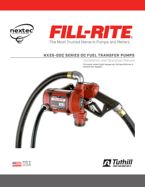
MADE IN USA NX25-DDC SERIES DC FUEL TRANSFER PUMPSInstallation and Operation ManualThis manual contains English language only. Visit todownload more languages.Table of ContentsLimited Warranty PolicyRevision Date: August 1, 2014 Fill-Rite and Sotera ProductsTuthill Transfer Systems ("Manufacturer") warrants each consumer buyer of its products ("Buyer") from date of sale that goods of its manufacture ("Goods") shall be free from defects of materials and workmanship.The duration of the warranty is as follows:* Proof of purchase should be presented to place of purchaseEnd users must contact the place where they purchased the product to process a warranty. “Place of purchase” is defined as any authorized Tuthill Transfer Systems Distributor, including any and all retail stores, mail order houses, catalogue houses, on-line stores, commercial distributors.Manufacturer’s sole obligation under the foregoing warranties will be limited to either – at Manufacturer’s option – replacing defective goods (subject to limitations hereinafter provided) or refunding the purchase price for such Goods theretofore paid by the buyer, and Buyers exclusive remedy for breach of any such warranties will be enforcement of such obligations of the Manufacturer. If the Manufacturer so requests the return of such Goods, the Goods will be redelivered to the manufacturer in accordance with Manufacturer’s instructions FOB Factory.The remedies contained herein shall constitute the sole recourse of the Buyer against the Manufacturer for breach of warranty. IN NO EVENT SHALL THE MANUFACTURER'S LIABILITY FOR ANY CLAIM FOR DAMAGES ARISING OUT OF THE MANUFACTURE, SALE, DELIVERY, OR USE OF THE GOODS EXCEED THE PURCHASE PRICE.The foregoing warranties will not extend to goods subject to misuse, neglect, accident, improper installation or maintenance, or have been repaired by anyone other than the Manufacturer or its authorized representative. THE FOREGOING WARRANTIES ARE EXCLUSIVE AND IN LIEU OF ALL OTHER WARRANTIES OF MERCHANTABILITY, FITNESS FOR PURPOSE OF ANY OTHER TYPE, WHETHER EXPRESSED OR IMPLIED. No person may vary the forgoing warranties or remedies, except in writing signed by a duly authorized officer of the Manufacturer. The Buyer's acceptance of delivery of the Goodsconstitutes acceptance of the foregoing warranties and remedies, and all conditions and limitations thereof.Unique nextec Features ........................................................3Safety Information ...............................................................3 Fueling Safety ......................................................................4Installation ...........................................................................4Nozzle Boot Installation .......................................................5Pump Foot Installation .........................................................5Anti-Siphon Device ..............................................................6Tank Installation ..................................................................6DC Power Connection .......................................................... 7Padlocking ..........................................................................7Operational Safety ...............................................................8Operating Instructions .........................................................8Dimensional Information .....................................................9Technical Information ........................................................10Accessories .........................................................................10Servicing the Bypass Valve .................................................11Replacement Parts Information .........................................12Servicing Rotor, Vanes and Shaft Seals .............................12Exploded View ....................................................................13Troubleshooting ...................................................................14Intelligent Tones ..................................................................15Safety Testing Certifications . (16)Thank You!Thank you for your purchase of the Fill-Rite ® NX25-DDC. Your Fill-Rite product comes with decades of pump manufacturing experience behind it, providing you the value that comes with superior performance, user friendly design, outstanding durability, and solid, simple engineering. Tuthill Pump Your Heart Into It.3 | Unique Features of the nextec PumpYour nextec fuel transfer pump will perform differently from non-intelligent pumps on start-up and while operating. You will want to keep the following in mind as you begin to use and learn how your nextec Intelligence™ pump operates.• On initial start up, the pump may rev momentarily, but will slow down, as if idling, as it reponds to the load it senses. This is a normal condition, and it will continueat this low speed until you squeeze the handle on the dispensing nozzle to begin fluid flow.• When you squeeze the nozzle handle to begin flow, the microprocessor in the pump will sense the change, and will raise the RPM’s to meet the load.It is not uncommon for the pump to change RPM’s during operation. It will do this as it senses performance parameters are changing; for example, if you increase or decrease the flow at the nozzle, the electronics controlling the motor will sense the changes and adjust the motor speed to optimize performance.• If the pump senses a condition that is outside normal operating parameters (low battery voltage, for example), it will sound a series of tones to alert you to thecondition, and to help you diagnose it. See the “Intelligent Tones” section of the Troubleshooting Guide on page 14 for greater detail on this feature.• Your NX25-DDC pump has a Continuous Duty Cycle, meaning it does not have to be shut off to “rest” after a specific period of use. This allows you to move fromfueling one piece of equipment to another without having to shut the pump off. The nextec Intelligence does, however, have an automatic shut off if the pump is left running in bypass mode (without dispensing any fluid) for 20 minutes. This features protects from excessive battery drain, as well as excessive uneccessary wear to the pump in the event you forget to shut the pump off. Should the pump turn itself off under these conditions, simply cycle the power switch off, then back on to restore pump operation.• The nextec Intelligence will also shut the motor down if: ►Pump temperature exceeds threshold parameters ►Supply voltage is outside threshold parameters ►Rotor is lockedAbout This ManualFrom initial concept and design through its final production, your Fill-Rite pump is built to give you years of trouble-free use. To ensure it provides that service, and to avoid injury or death, it is critical that you read this entire manual prior to attempting to install or operate your new pump. Become familiar with the terms and diagrams, and payclose attention to the highlighted areas with the following labels:At Tuthill, your satisfaction with our products is paramount to us. If you have questions or need assistance with your product, please contact us at 1-800-634-2695 (M-F 8 AM–6 PM ET).As a tank is being filled, air is displaced and exits via the fuel tank vent creating fumes, which when accumulated create an Explosive Atmosphere. To avoid possible explosion of accumulated vapors, it is critical to keep possible sources of spark / ignition at safe distances from the fuel vapors.The accompanying diagram shows minimum safe distances for safe fueling. 10’ is the minimum safe distance between:• Power source and fuel supply • Power source and tank being filled • Power source and pumpFueling SafetyInstallationYour Fill-Rite NX25-DDC pump is designed to be mobile for your convenience and safety. It can be installed / used in several configurations. Read each configurationprior to beginning installation.....5 | Nozzle Boot InstallationMounting pegPump Foot InstallationInstall the nozzle boot using the supplied attaching bolt. Note that the bolt is inserted through the hole closest to the nozzle opening, and the boot is then positioned so the peg on the pump mounting surface inserts in the top second hole of the boot. This allows for correct alignment of the nozzle when inserted into the boot.The mounting foot is bolted to the bottom of the pump using the four supplied socket head cap screws. Mount the foot with the bolt flanges inboard of the mounts on the pump as illustrated. Torque to 50 in lb. with 4 mm hex key.Materials:• 1-1/4” steel pipe cut to a length at least 3” above of the bottom of the tank when screwedinto the tank adapter, with the tank adapter screwed into the bung conection on top of the tank.• Thread pipe joint sealant appropriate for the application.1. Thread the 1-1/4” pipe into the tank adapter. Seal threads liquid tight with appropriate sealant (Figure 1).2. Screw the tank adapter (with suction pipe) into the tank bung; seal threads liquid tight with appropriate thread sealant (Figure 2).3. Mount the pump on the adapter; making sure the seal and screen are installed as shown (Figure 3).Tank InstallationThe NX25-DDC pump mounts to the bung of a tank by way of the tank adapter that is bolted to the inlet flange. The suction tube threads into the bottom of the tank adapter, and must be cut to a length that positions it at least 3” from the bottom of the tank. The tank must be equipped with a vent cap.Figure 2Figure 33" Min.Anti-Siphon DeviceNX25-DDC pumps come from the factory ready to install an anti-siphon tube back to the tank. An anti-siphon device (a.k.a. vacuum breaker) is important because it will break a liquid siphon if there is an open nozzle or a leaking hose below the fluid level in the tank when the pump is turned off. Fill-Rite recommends anti-siphon kit # KIT321ASN be installed from the pump outlet back to the vapor space in the tank.This illustration shows where to install the tube so that it terminates in the vapor space at the top of the tank. The tube must terminate in the vapor space; if it terminates below the fluid level in the tank, it will not prevent siphoning. It is very important there are no liquid traps in the tubing; it must have a continuous slope from the pump down to the tank, and can be connected into any opening in the top of the tank if the tank adapter is not used. Use reducer bushings as required for proper fit and seal.The ¼ NPT opening in the side of the tank adapter terminates in the vapor space of the tank. Make liquid-tight connections using the appropriate sealant from the adapter to the anti-siphon outlet using a minimum of ¼ metal tubing that is compatible with whatever liquid is being pumped. If the anti-siphon tank adapter is being used and the ¼ NPT opening is not used for the tubing, leave the factory installed plug in place.Fill-Rite offers Anti-Siphon kit # KIT321ASN (available through your Fill-Rite distributor). This kit contains the necessary fittings and tubing to complete the installation as pictured in this section. NOTE: This kit ONLY works for tank top installations.Anti-Siphon Line7 | Inspect power cable before each use! Damage to the outer jacket of the cable that exposes wiring requires replacement of the power cable.1. The green (ground) wire should be connected first. Connect the green wireto the vehicle chassis or earth ground. DO NOT connect the green wire to the negative power source post. 2. Next, connect the black (negative) wire to the negative post of the DC power source.3. Connect the red (positive) wire to the positive post last.Install power cable by aligning flat on plug with back of pump. Insert the plug into the motor housing as shown. Lock into place using the threaded collar (A). HAND TIGHTEN ONLY! Disconnect in reverse order.DC Power ConnectionAFlatPadlockingYour Fill-Rite pump nozzle can be padlocked to the pump for added security. With the pump turned off, and the nozzle in the stored position, a padlock can be inserted through the locking link and the nozzle handle opening. This configuration prevents the nozzle from being removed from the nozzle boot.The locking link is located on the nozzle side of the pump, and can be pivoted into position to work with a variety of nozzles.Use the appropriate position and hole to lock your nozzle securely to your NX25-DDC pump.Operating Instructions1. If so equipped, reset Meter to “0” (do not reset while in use as this can cause damage to the meter).2. Remove dispensing nozzle from nozzle boot.3. Move the switch lever to the “ON” (raised) position to start the motor (Figure 5). The pump should start and settle into a slow idle.4. Insert the dispensing nozzle into the container to be filled.5. Operate the nozzle to dispense fluid; release nozzle when the desired amount of fluid has been dispensed.6. Move switch lever to the “OFF” (lowered) position (Figure 6) to stop the motor.7. Remove the dispensing nozzle from the container being filled and store it in the nozzle boot.Operational SafetyFigure 6Switch “OFF”Figure 5Switch “ON”9NX25-DDC Dimensional InformationAll measurements are in inches [millimeters].Bung Mount Dimensional InformationFoot Mount Dimensional Information | Technical InformationAccessories | Servicing the Bypass Valve (Dis-assembly)1. Using needle nose pliers, place the bypass valve retainer on top of the bypass valve spring. Carefully align the slot in the top of the bypass valve retainer with the locking tab on top of the bypass valve (Figure 4).2. Push the bypass valve retainer down over the locking tab on the bypass valve. Push the retainer down (compressing the spring) until it is completely below the locking tab (Figure 5).3. Rotate the bypass valve retainer 90 degrees counter-clockwise and allow the spring to gently push it back up to contact the locking tab. The locking tab MUST be seated in the indentation in the bypass valve retainer (Figure 6).Servicing the Bypass Valve (Re-assembly)The bypass valve is located inside the pumphousing. It is accessed through the inlet and outlet openings.It consists of three main components (Figure 1):A. Bypass Valve Retainer B. Bypass Valve Spring C. Bypass Valve1. Unbolt the pump from the tank adapter.2. Using a blunt object approximately 4" long (i.e. a deep well socket on an extension) inserted in the inlet opening, push the bypass valve firmly in place against the seat it seals on (Figure 2).3. While holding the bypass valve firmly in place with the socket, insert needle nose pliers (at least 4" long) into the outlet opening and grasp the bypass valve retainer (Figure 2 & 3).4. Push the bypass valve retainer down slightly and rotate it 90 degrees counter-clockwise. This will align the slot in the retainer with the key on the valve, allowing you to remove the retainer (Figure 2 & 3).Figure 1Figure 3Figure 5Figure 6Figure 4KIT321JC - Junction box cover kitServicing Rotor, Vanes, and Shaft SealsThe rotor, vanes, and shaft seals are inside the pump housing, and are accessed through the rotor cover located on the face of the pump. It is held in place with three 4mm hex drive attaching bolts. You can access the rotor and vanes for inspection and cleaning, but DO NOT attempt to remove the shaft seals without a new seal kit to install.Always inspect the rotor cover seal and mating surface (groove) for nicks or damage prior to reassembly. Be certain o-ring is not pinched to prevent leakage. Torque the attaching hardware to 44 in-lbs.For repairs or routine maintenance, Fill-Rite offers the parts you need. The following parts diagram and list covers all applicable parts for your Fill-Rite product. These parts can be obtained through any authorized Fill-Rite dealer. Be sure to use only genuine Fill-RiteReplacement Parts InformationNX25-DDC Exploded View Bung Mount ConfigurationFoot Mount ConfigurationKIT321NBKIT321BGKIT321SWKIT320SLKIT321RGKIT321SWKIT320SLKIT321RG | This Troubleshooting guide provides basic diagnostic assistance. If you have further questions, contact us at 1-800-634-2695 (M-F 8 AM–6TroubleshootingBold text indicates repairs that are not serviceable by the owner; please refer to our warranty policy on page 2 for further instructions.*This condition will shut the motor off. | Intelligent TonesYour NX25-DDC pump features a self-diagnostic system that will aid you in troubleshooting should the need arise. The pump will give off a series of high and low tones; simply count the high and low tones to determine which conditions exist.Depending on the condition the pump senses, it will generate either a 3-tone code , or a 4-tone code :• 3-Tone codes indicate an application fault; something dealing with the installation of the pump, like a priming or supply voltage concern.• 4-Tone codes indicate a pump fault; a condition outside the operating parameters of the pump, like an over- temperature condition, or something dealing with thepumps internal electronics.Refer to the table below to determine which condition your pump is detecting, and how to resolve it. In the chart below, arrows pointing up (↑) indicate high tones, arrows pointing down (↓) indicate low tones; their order tells which fault is detected. Conditions listed in BOLD are not field servicable, and require the pump to be returned to the manufacturer.3-Tone Faults (Application / Installation faults)4-Tone Faults(Hardware faults)*This condition will shut the motor off. To restart the motor, cycle the switch off, then back on.** Prior to returning pump to place of purchase, perform this procedure: cycle the switch off and disconnect power for at least one minute. Reconnect power, and cycle the switch back on. Verify proper pump operation. If this procedure does not restart the pump, or if you have additional questions, contact Customer Service at 1-800-634-2695.This Troubleshooting guide provides basic diagnostic assistance. If you have further questions, contact us at 1-800-634-2695 (M-F 8 AM–5 PM ET), or on the web at “”.TroubleshootingTuthill Corporation | 8825 Aviation Drive Fort Wayne, Indiana 46809P (800) 634-2695 | (260) 747-7524 | F (800) | | DC002234-004 Rev. 4ATEXMADE INUSASafety Testing CertificationsThis Fill-Rite line of pumps have been safety tested for compliance to strict regulatory standards. Check the information on the motor barrel label of your pump to determine the certifications that are applicable to your particular model.The following standards were used to show compliance in North America:UL 674 – Electric Motors and Generators for Use in Hazardous (Classified) Locations, 5th Edition.The following standards were used to show compliance in the European Union:Directive 2006/42/EC – Directive on machinery.EN 809:1998 +A:2009 – Pumps and pump units for liquids – Common safety requirements.EN ISO 12100:2010 – Safety of Machinery – Basic concepts, general principles for design.Directive 2004/108/EC – Electromagnetic compatibility.Directive 2011/65/EU – Restrictions of the use of certain hazardous substances in electrical and electronic equipment.ISO 80079-36 = Explosive atmospheres - Part 36: Non-electrical equipment for explosive atmospheres - Basic method and requirements.ISO 80079-37 = Explosive atmospheres - Part 37: Non-electical equipment for explosive atmospheres - Non-electrical type of protection constructional safety “c”, control over ignition source “b”, liquid immursion “k”.EN 60079-0:2012+A11:2013 – Explosive atmospheres – Part 0: Equipment – General requirements.EN 60079-1:2014 – Explosive atmospheres – Part 1: Equipment protection by flameproof enclosures “d”.IEC 60079-0 – Explosive atmospheres – Part 0: Equipment – General requirements.IEC 60079-1 – Explosive atmospheres – Part 1: Equipment protection by flameproof enclosures “d”.The fasteners used to assemble the flame-proof enclosure are of a property class (grade) 12.9. Manufacturer is to be contacted for information on the dimensions of the flameproof joints.2809。
300MW机组交直流油泵使用说明书及结构示意图

125LY-35-4型交流润滑油泵 使用说明书成都泵类应用技术研究所目 录油泵结构示意图 附在目录后一、用途 2二、结构特点 2三、油泵的装配与拆卸 3四、安装 5五、 起动、停止、运转 5一、 用途125LY-35-4型交流润滑油泵用于输送透平油及具有润滑功能的各种流体润滑油。
型号说明125-油泵型号LY-表示立式油泵35-油泵的设计扬程(m)主要技术参数:流量:4100 l/min扬程:35 m转速:2950 r/min配套电机功率:45 KW交流配套电源:AC 380V出口管径:125 mm二、 结构特点125LY-35-4型交流润滑油泵主要由机座、轴承室、联接管、蜗壳、轴、叶轮等部件组成。
其结构特点是:联接管上端安装轴承室,轴承室内设有两列面对面安装的角接触球轴承,型号为7314ACM,承受整个转子部件的轴向力。
联接管联接蜗壳和泵座,蜗壳内设有导轴承,使其转子部分定心平稳运转,电机功率通过泵轴传递至蜗壳内叶轮,从而将透平油输送至工作管路。
推力轴承和导轴承的润滑都靠该泵抽送的润滑油来解决,该泵的导轴承用碳石墨材料,油磨性很好,但在无油情况下,空运行开机将在轴和导轴承间产生高温,从而烧坏导轴承,所以决不能无油开机运行。
泵的转向从电机端向下看为顺时针旋转,可以通过打开泵座观察孔看联轴器的转动方向来确认,转向是否与规定的转向一致。
该泵不能反转。
三、 油泵的装配与拆卸装配油泵装配前须先将各零部件去毛刺并反复清洗,确认清洁度达到要求后,再行装配。
油泵装配是先将两列已内装有球轴承套的角接触球轴承面对面地装在轴承室内,将轴承端盖和轴承外压圈依次装入轴承座内并对称带上四颗螺栓,将轴承座底部朝上倒立放置于一工装上,然后将轴直立从轴承座底端装入轴承座内,然后平放轴和轴承座部件, 取掉轴承端盖和轴承外压圈,装入圆螺母止退垫和圆螺母,将轴承内圈锁紧固定.切记一定要将止退垫外齿反扣入圆螺母的槽内,防止在泵运转中圆螺母松动造成整个转动部件下坠。
FILL-RITE 24V 直流 20GPM 燃油泵说明书

AÑOS
BOMBA PARA COMBUSTIBLE DE CC. DE 20GPM. DE 24V. MARCA “FILL-RITE”
ficha técnica . REF:FR 4410
DISTRIBUIDOR AUTORIZADO
DIRECTO TUTHILL
Bomba para combustible de CC 24V, serie 4400, de 20Gpm, con motor de 1/4 HP, incluye: manguera de 1" con longitud de 3,7Mts., y pistola manual de 1". Marca FILL RITE. La bomba cumple con las normas de la industria cuenta con un motor a prueba de explosiones con imán permanente. La tubería de succión de acero se extiende de 22 a 40 pulgadas. Ofrece válvula de control y filtro incorporados, manguera con alambre a tierra estático y protección contra sobrecarga térmica. Viene completa con una pistola manual. No incluye cables eléctricos. Se puede cerrar con candado. Esta bomba está diseñada para trabajar 30 MIN de forma continua y luego de esto debe tener un reposo de 15 MIN y continuar, esto para evitar que el motor se queme (la garantía no cubre partes eléctricas). La imagen presentada puede diferir de la presentación, color, referencia en caja o color del producto real, sin que este deje de prestar las funciones del mismo y cumplir con las mismas características técnicas.
水泵变频控制柜使用说明
上海东方泵业(集团)有限公司自动变频控制设备上海东方泵业(集团)有限公司目录一、概述 (2)二、设备特点、适用范围 (3)1、功能与优点 (3)2、适用范围 (3)三、设备主要技术指标及使用条件 (4)1、主要技术指标 (4)2、设备使用条件 (4)四、设备型号说明 (4)五、设备主要构成及工作原理 (5)六、变频恒压供水设备的安装接线 (7)1、控制柜外型 (7)2、控制柜规格 (7)3、禁止事项 (7)4、控制柜端子接线图 (8)5、控制设备电气安装接线要求 (9)七、设备的调试与使用 (10)1、设备的调试 (10)2、控制柜操作说明 (10)3、控制柜不同型号的差别 (10)4、使用与维护 (11)八、故障原因及对策 (11)一、概述DFK系列变频恒压供水自动控制设备系运用当今最先进的交流变频调速和微电脑控制技术,将变频调速器与电机水泵组合而成的新一代机电一体化高科技节能供水设备。
一般给水管网中的水压(自来水厂的一次供水压力)已很难满足用户的用水需求,除建筑低层可由市政管网直接供水外,其余高层用户均须“增”压供水。
无论是水塔、高位水箱,还是气压罐,都必须由水泵以高出用户实际所需水压的压力进行“提升”,从而造成能源的浪费。
水箱式供水的用户管网水压较稳定,具有一定的贮水能力。
但水箱(或水塔)的存在,增加了建筑物结构的承重和建筑造价,同时造成了水质的二次污染,且最高层不利水点水压不能满足用户需要。
气压式供水其实是把高位水箱移到了地面。
它虽可减少污染,并一定程度上消除“水锤”现象和管网中的噪音,但气压罐的有效容积有限,水泵电机启停十分频繁,管网压力波动较大;气压罐为钢制压力容器,还需使用胶囊隔膜或补气装置,运营费用高,潜在费用较高。
变频调速恒压供水设备以管网水压(或用户用水流量)为设定参数,通过微机控制变频器的输出频率从而自动调节水泵电机的转速,实现管网水压的闭环调节(PID),使供水系统自动恒稳于设定的压力值:即用水量增加时,频率提高,水泵转速加快,水泵供水量相应增大;用水量减少时,频率降低,水泵转速减慢,水泵供水量亦相应减小。
水泵控制柜操作说明手册

水泵控制柜操作
使用说明书
2013年9月15日制作设计
一.
1.、
、2.
3.
4.
二.
免水泵无水运行而造成水泵损坏。
1.手动-自动转换旋钮SA1在手动位置。
2.按下启动按钮1SB、2SB水泵运行,运行指示灯
1HG、2HG亮起。
3.按下停止按钮1SSB、2SSB水泵停止,运行指示
灯1HG、2HG熄灭。
4.故障时自动停泵,故障指示灯1HR、2HR亮起。
三.一控二自动控制
功能简介:控制柜接收五个水位信号(超停泵水
位、停泵水位、起单泵水位、起双泵
1.
2.1运
2 3.
4.
5.1
泵2不动作,收到超高水位信号时启动双泵。
6.泵1故障时泵1自动停止,并且自动切换到泵2
运行。
泵2故障时泵2自动停止,并且自动切换到
泵2运行。
四.BAS接口
本机与BAS通讯使用标准MODBUS-RTU协议,RS485通讯接口。
详情见附件记录:南京3号线BAS与车站排水泵接口功能测试大纲及记录.pdf
五.故障分析及排除
排除方法:修复故障或更换PLC
5.FU1熔断器保险丝熔断
分析:控制线路或到柜外的电缆有短路或漏电(浮球线缠绕破皮)
排除方法:查明线路受损短路处,更换保
险丝
6.PLC正常情况下BAS无法读取信号
分析:输出信号线接头松动,九针头子脱焊
排除方法:检查端子排X3的端子1、2电
六.。
智能型直流油泵控制柜

一、概述在电力、化工、钢铁、铸造、特种材料加工、环保、通讯领域中,广泛使用的备用蓄电池组动力系统中,所配备的直流电动机,在断电情况下为维持水冷却、油润滑功能。
需要迅速投入备用电源。
但由于直流电动机直接启动时,所需电流是额定电流的6-8倍,对备用蓄电池组冲击较大。
极易造成电动机线圈烧埙、损坏充电器、电路由于电流过大导致断路,出现这些现象时无法使设备正常运行。
我公司生产的系列直流电机控制系统是根据电力生产现场实际需要,广泛征求了电厂、设计院等专家技术人员的意见,参考吸收了国内外大量的先进设计思想和最新技术,用最新型的16位微机控制技术和电力电子技术开发研制,实现了该产品的高度可靠化和智能化。
拥有此项控制技术的成套控制设备,解决了直流电动机启动运行时对蓄电池组电源的冲击问题,保证了设备长期安全有效运行。
产品优点直流电动机启动时最显著的特点就是:启动电流大,最大冲击电流可达到额定电流的15-20倍,将使直流系统受到较大的电流冲击,电动机受到机械冲击。
针对这个特点,目前火力发电厂中应用最广泛的启动方式是电枢回路串接电阻启动,该启动方式启动时在直流电动机电枢回路中串入启动电阻,以限制启动电流,启动电阻为一个三个电阻串接的可变电阻,在启动过程中,开始启动时,电枢回路接入电源,串入全部电阻,以尽量降低启动电流,随后以固定时间及时逐级短接三个电阻,直到电机正常启动。
这种启动方式的应用在电力生产中非常广泛普遍,其暴露出的缺陷及隐患也是非常多的,大致有如下几项:1、它不能彻底解决直流电动机启动过程中冲击电流大的问题,启动过程中直流电机的启动电流依旧大于其额定电流数倍,仍有可能因启动电流过大而引起电机加速损坏。
2、控制原理落后,方式复杂,环节过多,故障率极高,维护工作量很大。
这种启动方式需由几个大容量的直流接触器和中间继电器、时间继电器组成,由于元件较多,故障率极高,柜体内非常拥挤,检修维护极不方便。
3、启动过程中,任何一级电阻不切换,即可导致直流电动机不能正常运行,电阻发热严重,电机过载。
直流油泵控制柜说明书

PI-ZK型直流润滑油泵控制柜产品使用说明书陕西普联电气有限公司直流润滑油泵控制系统一、主要功能与特点●直流润滑油泵系统往往在发电机组出现故障时启动的备用装置。
●采用现代电力电子器件、PWM技术、PLC技术于一体的无级调速系统,启停时对直流系统无冲击;●平衡电抗器与电容器的使用,使得电流输出平稳;容性直流输入母线的使用,抑制高频过冲脉冲●实现直流电动机的平滑软起,电流不突变,不对主厂房直流系统造成任何影响。
●控制器采用插拔式结构,便于安装检修●过流保护使得输出电流被限制在安全运行设定值,同时报警二、主要技术指标●工作电压DC 220V●智能监控,起动电流限制在额定电流的1.2倍以内。
●集直流电动机的过热、过流、过载、短路等多种保护于一身。
●人性化的中文人机界面。
●全中文故障信息显示和存贮。
●故障自诊断。
●多种信号输出(无源接点、RS485、4-20mA)。
●直流母线启动停止电压纹波最大值20V●室温下运行2小时,散热片温升小于摄氏25度三、运行控制方式●DCS控制:由上位机发出指令实现启停控制●母管控制:系统通常处于待机状态,油压低时自动启动运行●热工控制:热工控制台控实现启停控制●就地控制:在本地可通过手动操作转换开关控制启停四、运行状态控制●上电自检:当给控制柜提供220V直流电源,并合上机柜内的空气开关,系统将进行一次自检过程。
风扇电源启动,励磁继电器LJA、LJB闭合,控制继电器BJ也上电,向主控室送出合闸状态指示。
延时数秒后,风扇停止,励磁继电器LJA、LJB断开,控制继电器BJ断开,合闸指示结束,系统处于待机状态。
●待机状态:系统自检完成后将处于待机状态,等待主控室(或本地)的启动控制操作。
此时,继电器JJ带电,常开接点闭合并送到主控室被监视;系统的控制电路始终带电,而就地绿灯亮表示装置正处于待机状态;励磁继电器LJA、LJB断开,电枢电压为0,直流电机处于停机状态。
●启动控制:按启动按钮,装置开始软起动过程,首先励磁继电器LJA、LJB上电,对直流电机施加励磁,风扇启动运行;延时2秒后,电机开始软启动,经8秒左右后电机达到满速状态;继电器BJ 上电,同时送出两组信号,一组控制就地绿灯灭,而就地红灯点亮,表示装置处于运行状态;另一组送出到主控制室被监视。
- 1、下载文档前请自行甄别文档内容的完整性,平台不提供额外的编辑、内容补充、找答案等附加服务。
- 2、"仅部分预览"的文档,不可在线预览部分如存在完整性等问题,可反馈申请退款(可完整预览的文档不适用该条件!)。
- 3、如文档侵犯您的权益,请联系客服反馈,我们会尽快为您处理(人工客服工作时间:9:00-18:30)。
PI-ZK型直流润滑油泵
控制柜
产品使用说明书
陕西普联电气有限公司
直流润滑油泵控制系统
一、主要功能与特点
●直流润滑油泵系统往往在发电机组出现故障时启动的备用装置。
●采用现代电力电子器件、PWM技术、PLC技术于一体的无级调速系统,
启停时对直流系统无冲击;
●平衡电抗器与电容器的使用,使得电流输出平稳;容性直流输入母线的
使用,抑制高频过冲脉冲
●实现直流电动机的平滑软起,电流不突变,不对主厂房直流系统造成任
何影响。
●控制器采用插拔式结构,便于安装检修
●过流保护使得输出电流被限制在安全运行设定值,同时报警
二、主要技术指标
●工作电压DC 220V
●智能监控,起动电流限制在额定电流的1.2倍以内。
●集直流电动机的过热、过流、过载、短路等多种保护于一身。
●人性化的中文人机界面。
●全中文故障信息显示和存贮。
●故障自诊断。
●多种信号输出(无源接点、RS485、4-20mA)。
●直流母线启动停止电压纹波最大值20V
●室温下运行2小时,散热片温升小于摄氏25度
三、运行控制方式
●DCS控制:由上位机发出指令实现启停控制
●母管控制:系统通常处于待机状态,油压低时自动启动运行
●热工控制:热工控制台控实现启停控制
●就地控制:在本地可通过手动操作转换开关控制启停
四、运行状态控制
●上电自检:当给控制柜提供220V直流电源,并合上机柜内的空气开关,
系统将进行一次自检过程。
风扇电源启动,励磁继电器LJA、LJB
闭合,控制继电器BJ也上电,向主控室送出合闸状态指示。
延时
数秒后,风扇停止,励磁继电器LJA、LJB断开,控制继电器BJ
断开,合闸指示结束,系统处于待机状态。
●待机状态:系统自检完成后将处于待机状态,等待主控室(或本地)的
启动控制操作。
此时,继电器JJ带电,常开接点闭合并送到主控
室被监视;系统的控制电路始终带电,而就地绿灯亮表示装置正处
于待机状态;励磁继电器LJA、LJB断开,电枢电压为0,直流电
机处于停机状态。
●启动控制:按启动按钮,装置开始软起动过程,首先励磁继电器LJA、
LJB上电,对直流电机施加励磁,风扇启动运行;延时2秒后,电
机开始软启动,经8秒左右后电机达到满速状态;继电器BJ 上电,同时送出两组信号,一组控制就地绿灯灭,而就地红灯点亮,表示装置处于运行状态;另一组送出到主控制室被监视。
●
停机控制:按停止按钮,装置逐步减速,经2-3秒后装置恢复停止状态;
继电器BJ 失电,同时送出两组信号,一组控制面板绿灯亮,另一组送至主控室被监视;延时数秒后,励磁断开,风扇停止运行。
●
急停控制:按急停按钮(事故按钮),在软操、就地或母管、热工任一
状态下,当装置在工作状态下出现事故时,可在现场按急停按钮停止装置工作。
●
过流保护:系统出现过流状况时,就地黄灯亮,蜂鸣器鸣叫,同时控制
板的限流功能将电流限于恒定,避免系统遭受重大损失,此时电感器会由于通过开关脉冲电流而发出电噪声,过流状况保护设定值为额定电流的120%左右。
五、功率回路和监视信号接线图
(1) 功率回路端子定义及电机接线示意图
反馈变送器
监视变送器
分流器
1——220V+2——220V-3——电机公共端(220V-)4——励磁绕组(220V+)
6——电枢绕组(0~220V+)
电机公共端(220V-)励磁绕组(220V+)
电枢绕组(0~220V+)
直流电机接线示意图
5——空
(2)标准监视信号D端子排定义
六、控制柜内部系统原理图
七、控制柜内部系统布局图——单模块系统
八、检修用控制柜内部接线表
九、简易维护
1.供电后先检查TC端子处DC220V电源是否正常,如正常则合闸查看自检过程;如不正常请检查电源,不可合闸。
2.自检过程如不正常,则检查开关电源送出的DC+/-12V、DC24V是否正常,PLC、控制板供电电源是否正常。
3.自检功能正常,按下启动按钮,电枢无电流,请检查控制板。
4.如保险烧掉,请检查绝缘,是否发生短路现象,并检查器件有无损坏。
5.送至DCS的无源接点信号不正常,请检查相对应的继电器。