
直流润滑油泵控制箱中英文说明书(操作说明书)
JY-ZK IntelligentJY-ZK智能型DC Motor Control Cabinet直流电机控制箱Operation Manual使用说明书Shaanxi Jinyuan Automation Technology Co., Ltd.陕西金源自动化科技有限公司一、Overview 概述JY-ZK Intelligent DC motor control cabinet lubricating products are aimed at generating power plant system design a new type of lubricant replacement products, mainly used for steam turbine and generator of the main bearings, thrust bearing and the disk devices to provide lubricating oil vehicle control, as well as the generator seal oil system provides oil to ensure the safe operation of the pressure of the oil control. Generator control system equipment lubricants usually are:lubricating oil tank, main oil pumps, AC lubricating oil pump (#1 machine 2 Units), Oiler, and Oil cooler, emergency DC pumps, jacking oil pump system, oil-fume separate devices and purifying System and so on. In normal operation, all the lubricant oil supply from the main oil pump. When the main pump failure resulted in reduced a certain value, AC, DC lubrication pump automatically linkage.JY-ZK智能型直流润滑电机控制箱系列产品是针对发电厂发电机润滑油系统设计的新型换代产品,主要用于汽轮机和发电机各主轴承、推力轴承和盘车装臵提供润滑油的控制,以及对发电机密封油系统提供油源,确保系统安全运行的压力油控制。
发电机润滑油控制系统设备通常为:润滑油箱,主油泵、交流润滑油泵(#1机2台)、注油器、冷油器、事故直流油泵、顶轴油泵系统、油烟分离装臵和净油系统等组成。
系统在正常运行时,所有润滑油的油量由主油泵供给。
当主油泵故障导致油压降至一定值时,交、直流润滑油泵自动联动。
Traditional DC generators lubrication (sealed) pump motor control system for the 60's to start using the DC contact resistance switching, that is in DC motor armature circuit into the high-power resistor string, when the motor starts, through the step-down resistor to limit the motor starting current to rated current or speed to achieve a certain percentage, the adoption of DC contactor bypass resistance. This way to start the DC motor's advantages are: loop easy and cheap; its disadvantages are: 1,Resistors buck will start only when the motor start-up current to rated current of 2 times the DC system result in lower transient voltage affectthe relay protection of the normal work. 2, DC Contactors used in many frequent contact adhesion and carbonation phenomenon.传统的发电机直流润滑(密封)油泵电机控制系统为60年代开始使用的直流接触器切换电阻方式,即在直流电机的电枢回路中串入大功率电阻,当电机启动时,通过电阻降压来限制电动机的起动电流,使之电流或转速达到额定值的一定百分比时,通过直流接触器将电阻旁路。
通过这种方式来启动直流电动机的优点是:回路简单,造价低;其缺点是:1、电阻降压起动时只能将电动机的启动电流降至额定电流的2倍,会造成直流系统的电压瞬间降低,以致影响到继电保护的正常工作,2、直流接触器在多次使用后经常发生触点粘连和碳化现象。
My company to develop and produce the JY-ZK intelligent DC generator lubrication (sealed) pump motor control cabinet is a modern power electronic devices, PWM technology, and PLC technology in one high-tech products. It can achieve soft smooth DC motor, the current non-mutant, and the DC system will not be affected; the use of high-power power electronic devices to eliminate the DC contactor contact adhesion happen; with Remote Control (DCS) and the nearest control in two ways; can fault self-diagnosis, overheating, and other protection in one; Chinese man-machine interface operation and information display.我公司研制生产的JY-ZK智能型发电机直流润滑(密封)油泵电机控制箱是集现代电力电子器件、PWM技术、PLC技术于一体的高新技术产品。
它可以实现直流电动机的平滑软起,电流不突变,且直流系统工作不受影响;采用大功率电力电子器件,杜绝了直流接触器触点粘连的发生;设有远控(DCS)和就近控制两种方式;可以进行故障自诊断、过热、等多种保护于一体;中文人机界面操作和信息显示。
二、Principle Outlined 原理简述Adopting new PWM control of power electronic control mode of high-power semiconductor devices, conduction and shut off with PLC for the core management control, use voltage feedback form closed loop control of dc voltage, linear adjustment.According to proportional-plus-integralcontrol realization not static difference velocity modulation function, realization direct current machine reliable soft start.采用新型脉宽调制方式控制电力电子主控器件大功率半导体的导通与关断,以PLC为核心管理控制,利用电压负反馈形成闭环控制,进行对直流电压线性调节。
根据比例积分调节实现无静差调速作用,实现直流电机可靠的软启动。
三、Control Features控制特点High-power semiconductor devices with high job switching frequency, the saturation voltage drop small, high input impedance, voltage-driven and so on. In the velocity modulation system, uses by the control amplifierto control DC motor power source. Average armature voltage: Uav = Ton/ T.U s =ρUs, one of ρ= ton/T referred to as duty cycle. If the gate input voltagesignal frequency must change the pulse width, it changes the duty cycle, on the average armature voltage to change, and thus can achieve motor speed control.大功率半导体器件具有工作开关频率高,饱和压降小,输入阻抗高,电压驱动等特点。
在调速系统中,采用由控制放大器控制直流电动机的电源。
电枢电压的平均值为:Uav =Ton/T.Us=ρUs,其中ρ=ton/T称为占空比。
如果栅极输入电压信号的频率一定,改变脉冲宽度,就改变了占空比,电枢上的平均电压就改变了,进而可以实现电机的调速。
四、Speed control system block diagram 调速系统框图Speed control system by the intelligent controller control signals generated by the drive circuit isolation amplified drive high-power semiconductor devices, as shown in Figure1.调速系统由智能控制器产生控制信号,经驱动电路隔离放大后驱动大功率半导体器件,如图1所示图1直流调速原理框图五、Traditional control and JY-SPM control start waveform comparison (Figure 2 and Figure 3)传统控制与JY-SPM控制启动波形比较(如图2和图3)JY-SPM For my company JY-ZK control box used in intelligent control device for DC motor lubrication.JY-SPM为我公司JY-ZK控制箱中使用的智能型直流润滑电机控制装臵图2 图3六、JY-SPM Start Control Features JY-SPM启动控制特点1.Communicate lubricating oil pump protection in the system fails, DC pumps reliable interaction with the DCS system.保障交流润滑油泵在系统出现故障时,直流油泵可靠与DCS系统联动。
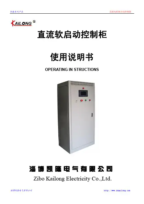
直流事故油泵控制柜技术规范和使用说明.doc
级电阻未正常切换,则恶化蓄电池的运行工况,对电气二次回路的正常工作造成威胁,
比如事故情况下部分接触器不能脱钩,使事故扩大。
电阻切换时,施加在电动机电枢绕组上的电压和电流呈阶跃上升,对电动机的冲击很大,
电机容易出现转速不正常、电刷火花过大、过热或冒烟等问题。
在停泵过程中,直流电机的反电动势,通过直流接触器断开时的电弧瞬时加入直流系统,
串接电阻启动并不能彻底解决直流电动机启动过程中冲击电流大的问题,启动过程中直 流电机的启动电流仍然大于其额定电流数倍,依旧有可能因启动电流过大而引起电机的
淄博凯隆电气有限公司
凯隆系列产品
损坏或者电路跳闸,导致启动失败。
直流电机软启动控制器
这种启动方式需由几个大容量的直流接触器和中间继电器、时间继电器组成,控制原理
导致直流系统电压大幅波动,严重时电压波动幅度大于 100V,对整个系统的正常工作造
成极大威胁,如现场运行中的开关无故跳开的现象,很多便是由此引起。
直流电动机最显著的特点就是:低速转矩大、启动后转速稳定,但启动电流大,最大冲击电 流可达到额定电流的 15~20 倍,将使供电系统受到极大的电流冲击,电动机和辅机也易受到强烈 的机械冲击。针对这点,以前各种需要直流电机作为备用动力的系统中,应用最广泛的启动方式是 电枢回路串接电阻启动,该方式是在直流电动机的电枢回路中串入启动电阻,以限制启动时的电压 和电流,类似于交流电机的自耦降压启动。启动电阻一般是一个或三个串接的电阻,在开始启动时, 电源接入电枢回路,并串入全部电阻,以降低启动电压和电流,随后在时间继电器的干预下,以固 定时间逐级退出三个电阻,以此来启动直流电机。由于以前受限于直流供电系统复杂的调控技术, 无法找到更好的控制方式,这种启动方式在以往生产中使用还是比较普遍的,但其暴露出的缺陷及 隐患也是比较多的,归纳起来,大致有如下几项:
YCB型齿轮泵使用维护说明书(英文)
Operation&Maintenance ManualGear Pump Type YCB Cangzhou Head Pump Co.,Ltd1.General1.1YCB series of circular arc gear pump is a new type external gear pump and of the latest construction,jointly developed by the Hydraulic Research Office of Mechanical Engineering Department,Shanghai Jiaotong Universitv,and Botou Gear Pump General Plant.The gears of pump have the teeth figure of the advanced arcs compounded with other curves,thus making it have good-working pared with the traditional Gear Pump2CY with involutes teeth,this pump has the characteristics of little pressure wave,low noise,high efficiency and long service life.It is a new type of energy-saving pump.1.2The circular arc gear pump is suitable for petrochemicals,ship-building industries and other industries to pump in different lubricating oil mediums,such as petroleum,heavy oil and industrial light oil,at a temperature below 70℃and with a viscosity5-1500cSt.But it is not suitable for pumping in oil with hard particles and the other fibred particles,nor is fit for high volatile but low flash point oil,such as gasoline,benzene medium liquid.1.3Safety valve is supplied with standard pump unless otherwise stated.1.4The pump is driven by the motor through the claw coupling,and they are fixed on a cast base plate or a welded from profile steel.1.5The circular arc gear pump can be installed horizontally or vertically or in other directions as required to meet different conditions.2.Model and standard technical data of gear pump2.1Model and standard technical data of pump2.1.1Motor power is chosen according to the shaft power,when the viscosity of oil is at30cSt.2.1.2The motor power should be raised along with the increase of the viscosity,the exhaust pressure or the exhaust pressure with safety valve.2.1.3Selection of the motor speed:Four-phase motor is for viscosity below500cSt;six-phase motor is for viscosity above500cSt.2.1.4The standard scope of viscosity:5-1500cSt.2.1.5Temperature below80℃2.1.6The direction of rotation is clockwise viewed from coupling end.(the pump-in entrance is on the left.And exhaust exit on the right)If the end users require to change the rotation,please indicate when ordering.2.2Model explanation YCB5—0.65capacity m3/h;0.6pressure MPa;B stands for“beng”which means PUMP in Chinese;C stands for“chi”which means GEAR in Chinese;Y stands for“yuan”which means circular arc in Chinese;3.working principle of gear pumpFig.1shows that a pair of gears that are engaged are installed inside the casing with two ends sealed by the front and back covers.Gears divide the inside of the casing into cavity A and cavity B which are not interlinking.When gears revolves as Fig.1indicates,cavity A’s volume is enlarged gradually because of the disconnection of the teeth,resulting in part vacuum,and oil in the tank flows through oil tubes into cavity A under the external atmosphere pressure.So cavity A is called as absorption cavity.The absorbed oil in the cavity A flows into cavity B in sealed space along the inside wall of casing when gears revolve.Oil between gear teeth are extruded out when they are engaged and therefore the volume of this cavity reduced.This is called as press oil cavity.When gears revolve constantly cavities A and B always pump in and exhaust oil,which is the working principle of the gear pump.Fig.1working principle of gear oil pump4.Pump construction and function4.1This pump series is characterized as simple construction and compactness.Pump body and safety valve are separated.So it’s easy to use and maintain.Quality of the product is guaranteed,for the main parts are made of top-quality steel and precisely processed.4.2Oil pump has the self-absorption function.So it is unnecessary to add oil before working.4.3Lubrication of pump is achieved automatically through the transmission of oil.So no lubrication oil is necessary while working.1.back cover2.gasket3.bush4.bearing stand5.driven shaft6.gear7.driving shaft8.front cover9.soft graphite10.press cover11.pump body12.safety valveFig.2Construction of gear pump4.4Pump bodyTwo holes on the parallel surfaces of pump body are fixed with a pair of gears and four bearing stands.Safety valves are put on the top.Front cover and back cover are in the front and back respectively.Flanges on both side are for connection.Flange connector dimensions are up to the ISO and DIN standards and that of the china state ship-building corporation’s CBM.4.5Gear and shaftAll gears are of spiral gears,the gear and shaft compose of the shaft gear.4.6Bearing stand and bushThe revolving of the shaft gear is backed up by bearing stand and bush that have already been put together as a whole.4.7GasketGasket are inserted into the press surfaces between the pump body and the front and the back covers in order toachieve the better results of the sealing.4.8Shaft seal4.8.1There are two kind of axle-end seals,mechanical seal and packing seal.The seal rings are made of soft graphite which are elastic,high and-low-temperature-resisting,and of chemical stability and self-lubrication.4.8.2Mechnical seal construction is shown as Fig.315.transmission stand16.spring17.o-seal ring18.Rotatimng seat19.stationary seat20.end coverFig.3Construction of mechanical seal4.9safety valve4.9.1The safety valve of this series of pumps is assembled on the pump body as a whole.If safety valve is not required,special cover fixed on the safety valve position can be provided.20.valve body21.spacer22.protective cap23.washer24.nut25.washer26.adjusting screw27.safety valve spring28.safety valve push pitch29.coverFig.4For pumps with safety valve and without safety valve,please see Fig.44.9.2The working principle of the safety valve is to use spring to control the working of the safety valve.The function of the safety valve is to avoid incidents that might result from too much high exhaust pressure.the breakage of the exhaust pipes or the close of the exhaust oil pipes’valves.When such incidents occur,safety valve opens immediately and the liquid part or even all,will flow back to the pumping in cavity.Safety valve is not used to adjust the capacity of the pump for long.5.Pump installation5.1Before assembling,it is required to check up whether the motor is affected by damp or there is damage to the dust-proof covers of pump’s inlet or outlet,which might lead the dirt things into the cavity.5.2Oil pump and motor are fixed on the base plate.Hooks must hang on the base plate rings.In lifting single pump head,hooks must hang on the inlet or exit flange tubes.Please see Fig.5.5.3Select a dry and bright place so that management people can watch when pump is working.A certain space should leave out if it is close to wall,for it is easy to maintain.Don’t put it at a place where is humid and wet, being exposed to sun and rain,Oil pump should be installed in place above the water level so that it can not befloodedFig.5Hoisting of oil pump5.4The foundation of pump should be stable so that pipes will not be released or vibrated.In order to avoid the deformation of the base plate,bolts should be fixed firmly.If only the pump head is installed on the machinery, the least vibrated place must be chosen.5.5Washing the inside wall of pipes by kerosene before installation in order that no dirt things especially no rubbing matters are allowed to remain in the pipe,because they might cause the damage to the gears.The dimensions of the absorption and exhaustion pipes are by no means smaller than the nominal size of pump. Absorption pipe should be bigger and the shorter the better.Elbow should have bigger radius.Throttle valve should be used on the pipe valves to reduce the resistance.5.6No foot valve is needed for oil pump.But it is suggested to fix a filter gauze at the entrance of the intake pipe to prevent dirt things from entering in pump body.The effective area of the filter gauze should not be two times smaller than that of the dimensions of the tubes.The mouth of the intake tube should be cut to an angle of450.5.7Pump shaft and motor shaft should be installed concentrically.If it is not properly fixed,it might cut off the claw of the shaft couplings when revolving6.Pump operation6.1Start-up6.1.1Before the oil pump to be used,it is required to check up whether all tubes are fixed properly,and open valves of intake oil pipes.6.1.2Revolve the couplings by hand to see if there is an abnormal phenomenon.6.1.3Press the button on shortly before oil pump starts and make it sure the revolving direction is right and everything is perfect.6.1.4If oil pump is in operation,close the control valve of the outlet oil pipes gradually so as to adjust the pressure required.But the adjusted pressure should not be higher than the rated pressure.When oil pump is in constant operation,shaft seal and vibration should be carefully observed.6.2Adjustment of the safety valve6.2.1In normal circumstance,the working pressure of the safety valve is1.5times as against the rated pressure.In case lower pressure is needed,adjust it according to Fig.46.2.2Release the protective cap and unscrew the adjusting nut.6.2.3Make the adjusting screw revolving clockwise and then close gradually the control valve on the outlet tubes to determine whether the returned pressure is that needed.If the requirement cannot be fulfilled through one time of adjustment,you should proceed with several times.6.2.4After the adjustment,screw the adjusting nut and protective cap.6.3Stop workingCut of motor power and close control valve on the outlet tubes.7.Pump disassembly and reassembly7.1Following orders should be followed to disassemble to oil pump.7.1.1Disassemble the couplings on the oil pump shaft end.If it is too tight,use a copper stick to hit it gently and let it out.7.1.2Disassemble the press cover first and then the soft graphite ring or mechanical seal ring.7.1.3Disassemble the front and back covers and take the gasket out.7.1.4Disassemble bearing stand and then take out driving-and driven-shaft gears.7.1.5Disassemble nut and spring washes of the driving-and driven-shaft and then take out the left and-right gears 7.1.6Disassembly of safety valveFirst disassembly the protective cap,gasket and nut,then unscrew the adjusting screws,springs and safety valve push pitch and lastly the valve body and gasket.7.2Oil pump check-outCheck out every part.Worn part must be repaired or replaced.7.3Oil pump reassembly7.3.1The procedure for assembling is nearly the reversal of that for disassembling,i.e.,last disassembled first assemble.But the following points should be noted.7.3.2All the parts must be checked before assembling.7.3.3All the parts that are going to be assembled must be washed with kerosene and lubricated.No dirt things are allowed to enter the inside while assembling7.3.4While assembling the upper and lower bearing stands and the driving and driven gears,the thickness difference of every pair of bearing stand and gear should be less than0.005mm.7.3.5The gap on both gear sides should be adjusted by paper gaskets.Bigger gap will easily cause the leakage and reduce the efficiency,but if the gap is too small,the pump will get a higher temperature quickly or can’t run freely.7.3.6Assembling the soft graphite ring or mechanical seal O-ring by special sleeve.Soft graphite ring must be handled with care and be put in order,and shown in Fig.67.3.7After assembling,use hand to revolve the driving gear,to make sure that it revolves evenly.Fig.6Driving axle sleeve soft graphite ringual trouble and ways of remedyTroubles Productive Reason Ways of remedyNo dischargingoil or discharging little oil 1.Revolving direction reversed2.Valve closed3.Oil absorption tube has not been soaked intothe oil4.The high of absorption exceeds the rated5.The filtering area of the filter at absorptionend is too small6.Air leakage in absorption tube7.Safety valve blocked or doesn’t work well8.Lower temperature of oil results in viscosityincreasing1.Change into right direction2.Open valve3.Check out oil absorption tube and soak itin the liquid4.Measure absorption pressure and raise theoil level5.Change filter and extend the filtering area6.Check every joint and seal them withsealing material7.Disassemble and wash safety valve andpolish with abrasive grease8.Heat liquid or reduce exhausting pressureor the volume of oil exhaustionNo pressure or pressure not rising 1.The button of the pressure meter is still inOFF position2.The pressure of the safety valve is too low3.Side tube valve is on4.High temperature,low viscosity of oil andsmall resistance of the tube5.Air leakage in the tube1.Press the button ON of the pressure meter2.Readjust the safety valve pressure3.Close the side tube valve4.Reduce oil temperature5.Check out absorption tubeOil leakagein mechanicalseal 1.Shaft seal has not been adjusted properly2.O-seal ring wear3.The defects caused by wearing of stationaryand rotating rings of mechanical seal4.Spring flabby1.Adjust it2.Change O-seal3.Change stationary and rotating rings orpolish them again4.Change springNoise and vibration 1.Improper assembling2.The in concentricity of pump shaft and motorshaft3.Absorption tube or filter stopped up4.Absorption tube dimension is too small andlong.It could not pump in,for resistance istoo big5.Oil exhaustion tube’s resistance is too big6.Air leakage7.Fastener is relaxed8.Gears and bearings stand sides show seriouswear and tear or gripped1.Check out and maintain2.Readjust it3.Clear dirt things in the absorption tube orfilter4.Readjust it5.Check up whether exhaustion tube orvalve are stopped up6.Check up and maintain7.Check up and tighten it8.Disassemble and maintain or change themSafelyvalve unworkable 1.Wrong position2.Pressure too high3.Safety valve chip gripped1.Reassembling it2.Lower the pressure3.Disassembling,wash and readjustOverload ofmotorpower 1.Exhaustion pressure too high2.Low temperature results in increase of oilviscosity3.Improper assembling4.Revolving shaft curved5.Somewhere in the exhaustion tube stopped1.Lower pressure2.Heat liquid or reduce exhaustion pressureor volume of exhaustion oil3.Reassembling4.Straighten or change it5.Check up and maintain it6.Gears and bearing stand sides show serious6.Disassemble and maintain or change themwear and tear or gripped9.Points for attention in operation and ways of maintenance9.1Points for attentionApart from the above-mentioned points,following points should be noted.9.1.1.Check up whether nuts and bolts,couplings and motor are tight.9.1.2Clear away the unnecessary dirt things and tools near the oil pump.9.1.3Operator is required to be at a distance from oil pump in operation to avoid being spattered with gushing oil.9.2Ways of maintenance9.2.1Pay attention to the pressure and vacuum meters,figures of which should be in accordance with those stipulated in the technical data.9.2.2Pay attention to the packing seal.If too much oil leakage,screw the press cover as required.If too tight,it will result the packing seal becoming excessive hot9.2.3When abnormal noise and excessive rise of temperature occur,turn off oil pump immediately to check up.9.2.4Check up timely and frequently and clear any stoppage.Be sure oil pump works properly.10.Spare parts,accessories and technical documents10.1Four oil seals(soft graphite)10.2Four foundation nuts with bolts10.3Operation and maintenance manual10.4Certificate of qualityOne copy of packing list。
直流油泵控制柜说明书

PI-ZK型直流润滑油泵控制柜产品使用说明书陕西普联电气有限公司直流润滑油泵控制系统一、主要功能与特点●直流润滑油泵系统往往在发电机组出现故障时启动的备用装置。
●采用现代电力电子器件、PWM技术、PLC技术于一体的无级调速系统,启停时对直流系统无冲击;●平衡电抗器与电容器的使用,使得电流输出平稳;容性直流输入母线的使用,抑制高频过冲脉冲●实现直流电动机的平滑软起,电流不突变,不对主厂房直流系统造成任何影响。
●控制器采用插拔式结构,便于安装检修●过流保护使得输出电流被限制在安全运行设定值,同时报警二、主要技术指标●工作电压DC 220V●智能监控,起动电流限制在额定电流的1.2倍以内。
●集直流电动机的过热、过流、过载、短路等多种保护于一身。
●人性化的中文人机界面。
●全中文故障信息显示和存贮。
●故障自诊断。
●多种信号输出(无源接点、RS485、4-20mA)。
●直流母线启动停止电压纹波最大值20V●室温下运行2小时,散热片温升小于摄氏25度三、运行控制方式●DCS控制:由上位机发出指令实现启停控制●母管控制:系统通常处于待机状态,油压低时自动启动运行●热工控制:热工控制台控实现启停控制●就地控制:在本地可通过手动操作转换开关控制启停四、运行状态控制●上电自检:当给控制柜提供220V直流电源,并合上机柜内的空气开关,系统将进行一次自检过程。
风扇电源启动,励磁继电器LJA、LJB闭合,控制继电器BJ也上电,向主控室送出合闸状态指示。
延时数秒后,风扇停止,励磁继电器LJA、LJB断开,控制继电器BJ断开,合闸指示结束,系统处于待机状态。
●待机状态:系统自检完成后将处于待机状态,等待主控室(或本地)的启动控制操作。
此时,继电器JJ带电,常开接点闭合并送到主控室被监视;系统的控制电路始终带电,而就地绿灯亮表示装置正处于待机状态;励磁继电器LJA、LJB断开,电枢电压为0,直流电机处于停机状态。
●启动控制:按启动按钮,装置开始软起动过程,首先励磁继电器LJA、LJB上电,对直流电机施加励磁,风扇启动运行;延时2秒后,电机开始软启动,经8秒左右后电机达到满速状态;继电器BJ 上电,同时送出两组信号,一组控制就地绿灯灭,而就地红灯点亮,表示装置处于运行状态;另一组送出到主控制室被监视。
齿轮油泵的产品说明书(中英文)

CONTRACTORSHANGHAI ELECTRIC GROUP CO. LTDPT. MAXIMA INFRASTRUKTURGear Oil Pump Production Instruction 齿轮油泵产品说明书四川高精净化设备有限公司SICHUAN FINE PURIFICATION EQUIPMENT CORP.LTD1.RIEF INTRODUCTIONWith history of more than 20 years in producing large separation equipment, our compary manufactures Model ZJA High Vacuum Oil Purifier, ZLY Vacuum Oil Filter, JYG Fine Filter,BMS, BAS Manual/Automatic Board Frame Press Oil Filter Which are designed for filtering turbine oil, transformer oil, aviation hydraulic oil, machine oils and Diesel fuel. Besides, We produce WCB,KCB,2CY Geared Oil Delivery Pumps suitable for delivering various medium oils.Model WCB, KCB,2CY Gear Oil Pumps are suitable for fertilizer factory, oil refinery, oil-pressing factory, power plant, transformer station, lubrication oil storehouse, capacitor plant, painting factory and grain departments for delivering oils, such as turbine oil ,transformer oil, aviation oil, mechanical oil, diesel oil and edible oil.WCB,KCB Geared Oil Pump features of good appearance, compact construction, stable performance, low pulsation impact value and low noise less than the specified of the national standard, safety and reliability as well as easy maintenance and service. We provide our customers with wear parts for a long term.Series of gear oil pumps produced by our company find their wide use in national defense, scientific research, Petroleum, light/chemical industry, metallurgy, textile, transportation, Pharmaceutical-making and food departments for delivering non-corrosion heavy oil, mid-viscosity oil, light oil, edible oil and other similes with viscosity below Engler 10°E at temperature below 60℃.However, they are not suitable for delivering dirty oils, lubricating/corrosive medium. Explosion-proof motors and special motors can be provided according to user's requirements.Model WCB Geared oil pump is of one with excellent performance and reasonable price. It can be used in grain sales department for delivering edible oil with illumination power.2.SPECIFICATION3. CONSTRUCTION AND OPERATION PRINCIPLE3.1StructureGeared pump is composed of body ,front/back end cover, driving gear, driven gear, bearings, bearing cap, oilseal coupling, motor, chassis, inlet/oulet oil pipe, flange and safety valve etc.Front/back end cover supports driving/driven gear by means of bearings. The body enables driving gear and driven gear to rotate, resulting in vacuum operation mode. Oilseal acts as sealing of driving shaft. Motor drives driving gear through coupling and shaft pin.2.Moving Sketch3.2 Operation PrincipleWhen driving shaft drives Gear1and Gear2 to rotate in direction shown by arrow and geared teeth disengage gradually in oil suction cavity, teeth disengage from teeth of another gear so that vacuum is formed. aˊ,bˊ…of a, b…between teeth carries oil from oil suction cavity to oil discharge cavity. Oil in geared space is pressed out when gear rotates continuously. Outer load action causes oil pressure. With continuous running of gear, oil pump sucks and discharges oil continuously.When resistance of oil circuit exceed safety Pressure, safety valve starts to make oil in discharge cavity go back suction cavity. In doing so, pressure is reduced and pump/piping is protected.4.INSTALATION AND CONISSIONINGGeared pump and motor is fixed on chassis. Shaft line between motor and geared pump has been adjusted. Geared pump rotates smoothly.During operation, keep an eye to suction height. Rated lift can be obtained. Specified oil inlet/outlet pipes should be chosen. Oil inlet should be through. Before starting, check to see whether fasteners are loose and whether geared pump moves freely. Idle running can't last more than 1 minute. If no oil is sucked in, check geared pump for correct rotation(Running in direction shown by arrow).Check to see whether oil suction pipe joint is loose, connections are leaky and oil groove bottom is blocked by oil suction pipe inserted as well as oil suction height and oil outlet height exceeds tolerance.No abnormal noise and vibration should occur when geared pump works.Safety valve was set in specified safe pressure scope at factory. Users can regulate it. But max regulation puessure can't exceed 40%.5.OPERATION5.1 Before operation, check to see whether geared pump moves freely(Turn by hand).5.2 Make sure power supply is OK and rotation direction of motor is correct.5.3 Check to see whether oil inlet/outlet diameter meets requirements and lift is within specified range.5.4Make sure that all fasteners are firm (Including connectors of inlet/outlet pipe)5.5Before starting, insert oil inlet pipe into oil groove properly. Oil pipe can't reach to groovebottom to prevent blocking intake.5.6Only everything is OK, you may start machine.6.MAINTENANCE AND SAFETY6.1 Connect grounding device6.2 Always keep an eye to loosening of fasteners and abnormal noise of geared pump.6.3 Corse filter should be mounted at oil inlet to prevent iron and impurities from entering pump. 6.4 Oil seal is wear part. In case that driving shaft leaks oil, change oil seal.6.5 Oil pump adopts ball bearings. If ball bearings are worn out, serious noise will occur. Replacement should be made.6.6 After service is completed, made sure that axial gap of the pump, and concentricity should be within tolerance. Otherwise, Pump will fail to work properly.6.7 Geared pump is not allowed to operate in environment and the open-air with high temperature.7.TROUBLESHOOTING AND REMEDYMAIN PARTS AND MATERIALS TABLEBEARING CATALOGUESPARE PART AND WEAR PART CATALGUESPARE PART AND WEAR PART CATALGUEOVERALL AND INSTALLATION DIMEMSIONS OF OIL PUMP一、简介我厂已有二十多年制造分离大型机械设备的历史,产品为各发电厂或从事电力事业的单位提供ZJA系列高真空净油机、ZLY系列真空滤油机、JYG系列精密过滤机、BMS、BAS系列手动和自动板框压滤机、LY系列板框滤油机过滤透平油、变压器油、航空液压油、机油、柴油,还为客户提供WCB、KCB、2CY系列齿轮输油泵,输送各类不同用途的介质油液。
滑油预供泵说明书(中文)

R25,R35,R45,R65,R95系列 Page 1(8)内 容 页 内 容 页一般说明 2 5.2 旋转方向和流向 51 齿轮泵的使用2 5.3 旋转方向的转换 52 流体介质 2 6 试运行 53 危险 2 7 运行/功能 63.1 安全工作程序 2 7.1 安全阀 63.2 不遵守安全规范可能导致的危险 2 7.2 干转 63.3安全阀的调整R25、R35 2 7.3 环境保护 64 运输和存储 3 8 拆卸 74.1 储存 3 9 维护/服务 74.2 泵/泵单元的起吊 3 10 齿轮泵配置的改变 75 安装 4 11 报废 75.1 进口管设计, 值 4 12 故障/原因/故障排除措施 7(必须的汽蚀余量值)一般说明除了操作说明外,下列各项说明也必须注意:1.和产品一起发运的Rickmeier的数据清单.2.万一运行环境与数据清单中的情形有所偏差,请遵守Rickmeier泵中适用的操作说明和限制.3.其他说明(泵单元,驱动马达的操作说明).4.当在潜在爆炸的环境中使用时, Rickmeier的ATEX操作说明BA 2-0NNN-113也必须遵守.在泵上使用的信息应优先采用.在机器的操作场所应始终有相关的文件,以最大程度的避免危险和伤害.泵的储存、运输、试运行、运行、维护/服务或报废,,必须遵守相应的国家和具体行业的相关规定.专用的设计和设计变形或许与技术资料中不同.万一有不清楚的地方,强烈推荐与制造商联系,并索取泵/泵单元的规格和相关资料.基本安全规则安装、试运行、运行、维护/服务或报废,必须由专门的人员完成,其必须:1.仔细阅读和理解操作/安装说明2.经过相关培训并得到授权来执行这样的工作.3.工作设备必须符合EC 89/655/EEC中的最基本的安全和健康要求.直接附在泵上的信息,如旋转方向和管路连接标记必须要遵守.这些应置于明显的位置.如果操作说明是适用泵的单元,那么马达和离合器的操作说明也是其一部分.R25,R35,R45,R65,R95系列 Page 2(8)1、齿轮泵的使用Rickmeier齿轮泵仅用来输送有润滑特性的流体.如果需要有单独的数据清单、图纸、或相似文件,应在Rickmeier的定单中注明.如果在后来使用时与规定的工作环境不符,必须和制造商协调,否则所有的担保承诺将无效.当泵/泵单元有相应的标识,才允许在具有潜在的爆炸危险的环境中使用.2、 流体介质作为长的使用寿命和最大安全运行的条件,使用的流体介质必须有润滑特性.( 在所有的 运行条件下,流体的运动粘度>5mm2/s.). 使用流体的污染程度不应大于ISO4406:1999纯度等级21/19/17的规定. 流体必须没有硬的固体颗粒.,流体中不溶解的气体(气泡)百分比不应超过流量的10%,否则可能导致噪声增大.3、危险3.1 安全工作程序在本操作说明书中列出的安全措施,现有的国家预防事故的规范以及内部的操作人员的操作和安全规章制度必须遵守.3.2不遵守安全规范可能导致的危险不遵守安全规范会导致人员、环境、机器发生危险或损坏. 由于不遵守安全规范导致的损坏,将失去所有的担保承诺.尤其,不遵守安全规范可能导致以下危险:1.人员的危险,例如由于燃烧和中毒2.泄漏(例如轴封损坏)的危险流体(例如爆炸的、有毒的、高温的)必须导出,以防造成对人员和环境的危害.但必须符合相关的法律法规.3.如果机器过热或过冷的部分会导致危险,那么这些部分必须由用户进行防护,以防止接触到这些部分.4.机器/系统的重要功能的丧失.5.缩短机器/系统的预期服务寿命.6.维护说明和保养方法的失效.不要通过对机器的修改移走安全装置或使其失效.3.3安全阀的调整R25,R35安全阀是用来保护泵防止其过载. 开启压力在出厂时已经设定,运行期间只是偶尔动作.R25,R35,R45,R65,R95系列 Page 3(8)图1 安全阀R25,R35 表1 拧紧力矩万一以后调节压力,应按以下内容进行:1.拆下盖形螺母件4(32mm).2.松开六角螺母件6(32mm)3.通过调节螺杆件3来调节压力.警告!在压力调节期间时, 螺杆(件3)仅允许顺时针旋转(压力增长),否则将发生3.2中的危险.螺杆反向旋出不安全4.更换铜密封圈件9(两个) (DIN7603-A21X26-Cu).5.拧紧六角螺母件6,见图1, 用螺丝起子在槽中控制螺杆,以防跟转.6.装上盖形螺母件4,见图1.4、 运输和存储根据相关的规定,在拆箱后处理包装材料.4.1储存为了防止泵由于潮湿、灰尘、水或其他杂质造成的损害,将泵存储在干净、干燥的地方(相对湿度<70%)温度在-25C和40C之间.带有旋转轴封的泵在装船后最迟应在六个月后运行.不符合储存环境应征得同意.4.2起吊泵/泵单元用起吊带安全地起吊泵,重心必须位于带中间以防止泵倾斜(见图2).必须使用合适的起重机.图2 运输/起吊R25,R35,R45,R65,R95系列 Page 4(8)5.安装泵必须根据订货时的约定安装.齿轮泵运行按输入功率进行调整.管路安装应使安装应力尽可能的小,泵的进口和出口具有内螺纹接口,只能使用精确的圆柱管螺纹联接.当螺纹联接后,确信泵安装不扭曲错位.接口必须按照运行状况(液体压力、温度)密封.泵的连接法兰表面和相应配合表面应无损伤,必须没有油漆和其他污物体.驱动元件比如离合器,齿轮是按精度为H7的ISO标准安装在泵轴上.这些部件不允许用锤子来敲击,以免泵被损坏.当泵轴连接到驱动装置上对中时, 不能超过离合器的允许偏差.(见相关离合器的操作说明书)保证平滑接触,好的基础或法兰安装和精确连接.对于工厂没有安装离合器防护的泵, 顾客需安装相应的防护装置(可参见机械设计手册相关的章节).必须采取合适的措施防止长期的灰尘,水, 直接暴露到阳光等影响(例如大区域保护) .流动流体接触的所有部件必须没有杂质. 尤其重要的是热弯或焊接的管路,试运转时要确保管内没有杂质.5.1吸口管路设计,NPSHR值为了保证泵正常运行, 任何情况下,泵吸口的静压不能低于-0.4bar(等于绝对压力0.6bar).偏离此要求时必须在定货时征得制造商的同意.在运行期间,建议计算或测量泵的进口最低的静止压力.当进行此工作时,必须将吸口管路的阻力考虑在内,尤其是当在吸口管路中安装有可能造成阻塞的滤器时.在这种情况下,建议在尽可能靠近泵的的地方用一个压力装置来监测进口压力和必须对滤器进行规 流体密度 [kg/m3]范的维护. 图3 NPSHR如果在管路中不能安装测量接头,带减压阀的泵的吸口侧的压力测量接头也可以用作该用途.此外,泵的吸口管路必须绝对的无泄漏以防吸入空气.图3提供了通常使用的NPSHR值(必须的汽蚀余量值),用于和系统的NPSHRA值(必须有效的汽蚀余量值)进行比较.R25,R35,R45,R65,R95系列 Page 5(8)5.2旋转方向和流向在泵使用之前,必须保证驱动装置旋转方向和泵的旋转方向相匹配.为检查驱动机装置的旋转方向,将离合器分开以使泵不被驱动.如果不能这样做,那么至少应将泵的连接管路拆除,以避免使泵由于不正确的旋转方而造成损坏.当检查驱动装置时, 必须防止在泵吸口处管路内压力的形成(例如由整体的单向阀产生).否则万一旋转方向不正确,轴封可能损坏.图4旋转方向和流向5.3旋转方向的转换尺寸从R25到R65的泵将旋转的方向设计为可以改变式..在改变旋转方向、输送的流体流向倒转之前,必须和制造商联系.6、试运行在启动之前,泵和吸口或供应管路必须充满流体.如果安装泵时齿轮一上一下水平布置,即使泵处于备用状态,泵中仍会残存有少量的流体,那么,即使在长时间静止后,重新启动时,泵依然保能持其抽吸能力.当两个泵并联运行时,在两个泵的压力侧安装可相互保护的单向阀.(单向阀)同样也应用于封闭系统中单独工作的泵.由于可能使泵发生不允许的温度上升,封闭的压力管路加压是不允许的.在抽吸困难的情况下,泵安装时应使齿轮一上一下水平布置.在长时间停用后,由于在泵中残存有少量的油,该安装位置保证泵更好地工作.当吸口管路上装有单向阀时,可防止齿轮泵干转.这也可以通过将吸口管路和压力管路以虹吸管的形式位于布置在泵上获得.R25,R35,R45,R65,R95系列 Page 6(8)7、运行/功能齿轮泵是转子容积泵.当齿轮转动,封闭在齿型空间从泵的吸口被转移至压力侧(见图5).朝压力侧的流体输送由互相啮合的轮齿执行. 流体的不断输送导致泵的吸口侧压力下降. 于是流体便不停地流入泵的吸口以补偿该压力降,泵便可不停的进行流体的传输.吸取输送排出图5 齿轮泵的输送原理该过程对于输送气体和液体来讲是一样的.结果是泵具有了自吸能力直到它充满被输送的介质7.1安全阀安全阀在泵的端盖上,设计为弹簧控制的阀.作为压力限制用,它仅是偶尔短暂地开启.如果长期地有比较大的泄放量,管路中应单独安装一个带回油管到泵吸口的阀(例如Rickmeier的阀RSn,DBV40,DBV80,DB89)或其他形式的安全阀. 这也适用于在运转期间泵可能被完全堵塞的情况.在他们的技术细节中,特殊设计和变形或许和技术资料上有所不同.7.2干转应当避免泵干转, 也就是说在运转之前,泵必须满被输送的流体.例外: 当泵的吸管中无流体就起动或运行期间流体供应中断时,泵会经常发生干转. 如果泵被流体预润滑过,在以下情形时可运转达20分钟.1. 泵是通过离合器驱动的2. 泵的进、出口压力大致相等通过小齿轮、链或带驱动的泵,干转是不允许的,必须由操作者避免(在起动前用流体充满泵)7.3环境保护安装时泵中的流体如果没有完全泄放, 流体可能流到泵下的地面.在长期运行后也可能显示磨损迹象.若轴封在维护过程中没有更换,可能会发生泄漏.为避免由于流体泄漏可能发生的损伤,应采取安全措施,例如在泵下安装一个集油盘等.8. 拆卸流体发生泄漏可能给人和环境造成损伤.因此,必须根据流体的安全性采取措施.另外,必须遵守在7.3中的介绍.R25,R35,R45,R65,R95系列 Page 7(8)9维护/服务通常当泵在允许的限制内运行, Rickmeier齿轮泵几乎不需要维护.如果齿轮泵由于磨损而不能使用,它必须更换. 一般情况下,更换零件后的性能通常不能恢复到原来的状态.轴封的服务寿命通常取决于泵的操作方式和流体的清洁度和质量.结果在许多情况下都不能对其使用寿命做可靠的预测.因此,对于带有轴封的泵,建议定期进行外部目视检查液体泄漏情况.(建议:在48小时后,然后在每运行4,000小时).如果由于输送的流体有潜在的高危险性,应在更短的时间间隔进行检查.当在潜在爆炸环境中使用, 相关的维护周期ATEX操作说明BA 2-0NNN-113也必须遵守泵单元的维护也应符合以下维护间隔和工作:1. 离合器操作说明书2. 驱动马达操作说明书10齿轮泵配置的改变在和制造商协商并得到允许后才能对齿轮泵的配置进行改变.由制造商授权的正宗备件和附件能保证安全. 对使用其他没被授权的备件可能导致结果不负责任.订购备件,请提供在标牌上的数据.11报废报废泵时,必须保证在泵中没有大于大气压力的压力存在,泵的驱动装置不能意外起动.另外必须遵守在7.3中的介绍.由于环境保护原因, 泵/泵单元的处理应得到专业公司的许可.12故障/原因/故障排除措施下表列出了可能发生的故障和可能的原因,如果发生这里没有提及的故障,我们建议咨询制造商. 如果为排除故障,必须拆下泵,必须遵守在7.3和11中的介绍.R25,R35,R45,R65,R95系列Page 8(8)故障泵没有吸入泵没有排出泵吸入不足或出口压力太低 在运行期间泵的噪声大出口压力太高泵不起动,突然停止安全阀导致噪音措施观察泵的转向是否和泵上的转向箭头标识一致,如必要,改变电动马达的极性检查泵是否充满流体接头或许泄漏.检查泵的吸管和轴封的泄漏.若装有安全阀,检查密封圈的情况,如必要更新在泵吸管中压力下降太快,如有可能,增大管径,缩短管字的长度或增高液面,如安装有滤器,如必要,进行清洗或加大滤器流量安全阀启开压力和定货的数据是否相同?如必要, 开启压力增大10%检查安全阀是否被污染或损坏,阀的活塞是运动平稳检查疏通压力侧管道检查开关类型,驱动马达的转速和电流, 和马达标牌上的额定电压和频率比较如果是稀薄的流体低压输送,换用设定压力为1-2bar 的泵根据定货要求,最大允许速度超过了吗输送高的挥发性介质(汽油、溶剂、油漆等)时, 介质必须流进泵内消除流体中的气泡(例如回油管末端在油箱油位之下)马达输出功率是否与定货的数据一致检查流是否由于过度高温而失去润滑性检查从密封腔到泵吸口的泄放孔是否堵塞检查流体的粘度是否和定货的数据一致所用的泵太小泵的管路或许没有安装好,拆下泵,检查管路表2 故障排除。
直流润滑油泵控制箱中英文说明书(操作说明书)

JY-ZK IntelligentJY-ZK智能型DC MotorControl Cabinet直流电机控制箱Operation Manual使用说明书Shaanxi Jinyuan Automation Technology Co., Ltd.XX金源自动化科技XX一、Overview概述JY-ZK Intelligent DC motor control cabinet lubricating products are aimed at generating power plant system design a new type of lubricant replacement products, mainly used for steam turbine and generator of the main bearings, thrust bearing and the disk devices to provide lubricating oil vehicle control, as well as the generator seal oil system provides oil to ensure the safe operation of the pressure of the oil control. Generator control system equipment lubricants usually are:lubricating oil tank, main oil pumps, AC lubricating oil pump (#1 machine 2 Units), Oiler,and Oil cooler, emergencyDC pumps, jacking oil pumpsystem, oil-fume separatedevices andpurifyingSystem and so on. In normal operation, all the lubricant oil supply from the main oil pump. When the main pump failure resulted in reduced a certain value, AC, DC lubrication pump automatically linkage.JY-ZK智能型直流润滑电机控制箱系列产品是针对发电厂发电机润滑油系统设计的新型换代产品,主要用于汽轮机和发电机各主轴承、推力轴承和盘车装置提供润滑油的控制,以及对发电XX封油系统提供油源,确保系统平安运行的压力油控制。
润滑油泵操作说明
润滑油泵操作说明润滑油泵是工业生产中常用的设备之一,广泛应用于机械设备的润滑系统中。
正确的操作润滑油泵能够保证机械设备的高效运转和延长其使用寿命。
本文将详细介绍润滑油泵的操作步骤和注意事项,以帮助您正确、安全地使用润滑油泵。
一、操作步骤1. 准备工作在操作润滑油泵之前,首先需要检查相关设备和工具是否完好,并确保所有安全措施已经采取。
检查油泵、管道、接头等设备,确保无泄漏现象。
准备好所需的润滑油和润滑脂。
2. 开启油泵使用油泵开关或按钮将润滑油泵启动。
听到油泵发动机启动后,确认油泵工作正常。
3. 调整油泵压力根据机械设备的要求,调整油泵的压力。
通过调整调压阀来实现,确保压力在设备要求的范围内。
4. 连接润滑系统将润滑油泵与机械设备的润滑系统连接。
通常这包括连接润滑脂管道或油管道,并确保连接牢固、无漏油现象。
5. 开启油泵增压在连接润滑系统后,打开油泵的增压开关。
润滑油泵将开始将润滑油或润滑脂送入机械设备的润滑系统。
6. 观察润滑情况在油泵工作期间,需随时观察润滑情况。
确保润滑油或润滑脂正常流动,并在润滑点处提供足够的润滑。
7. 关闭油泵当工作完成或需要停止润滑时,关闭油泵开关。
等待油泵停止工作后,断开与机械设备的润滑系统的连接。
8. 清洁和维护操作结束后,清洁润滑油泵和相关设备。
定期进行维护工作,包括更换润滑油、润滑脂等,并确保设备安全可靠。
二、注意事项1. 安全操作操作润滑油泵时,要严格按照操作规程进行,不得擅自变更或忽略任何步骤。
在操作过程中,要注意个人安全,佩戴好劳动防护用品。
2. 维护保养定期检查润滑油泵的工作状态,了解其运行情况。
及时更换润滑油、润滑脂等,并清洁油泵和管道以保持系统的正常运转。
3. 压力控制在操作润滑油泵时,一定要根据机械设备的要求调整油泵的压力。
过高或过低的压力都会导致润滑不良。
4. 泄漏处理如发现润滑油泵或润滑系统有泄漏现象,应立即停止使用,并进行检修和处理。
泄漏会导致浪费、污染等问题,应予以重视。
润滑油泵设备操作说明
润滑油泵设备操作说明润滑油泵设备是工业生产和设备维护中常用的设备之一。
本文将详细介绍润滑油泵设备的操作说明,以帮助用户正确、安全地操作设备。
一、设备介绍润滑油泵设备是一种用于输送润滑油的设备,通过机械力或电力驱动,将润滑油从油箱或储油罐中吸入,通过管道输送至需要润滑的设备部位。
润滑油泵设备通常由泵体、电动机、控制面板和输油管路等部分组成。
二、设备操作前的准备1. 确保设备安全:在进行操作之前,必须确保设备处于安全状态,无异常。
如发现设备存在故障或损坏,应及时联系维修人员进行维修。
2. 密封件检查:检查润滑油泵设备的密封件是否完好无损,如有损坏或老化的情况应及时更换,以保证设备的正常运行。
3. 润滑油选择:选择适合设备的润滑油,按照设备规定的要求添加到油箱或储油罐中。
三、设备操作步骤1. 启动设备:按照设备操作面板上的启动按钮,启动润滑油泵设备,确保设备正常运行。
2. 正确调整泵速:根据设备的工作需要,调整泵速,保证润滑油的输送量满足设备所需的润滑要求。
3. 观察设备运行状态:在设备运行过程中,应时刻观察设备的运行状态。
注意检查泵体是否有异常噪音、振动等情况,并观察油液泵出口是否正常。
4. 定期检查润滑油量:根据设备要求,定期检查润滑油的油位是否符合要求,若油位过低,应及时补充润滑油。
5. 关闭设备:当设备使用完毕或需要停机时,在关闭电源前,应先关闭润滑油泵设备。
四、设备维护保养1. 清洁设备:定期清洁润滑油泵设备的外部表面,避免灰尘和污垢积累,影响设备的散热和正常运行。
2. 定期更换润滑油:根据设备的使用情况,定期更换润滑油,以保证润滑油的性能和质量。
3. 密封件维护:定期检查润滑油泵设备的密封件,如发现老化或损坏的情况,及时更换,以免泄漏导致设备故障。
4. 保持设备干燥:润滑油泵设备在存放和运行过程中,应保持干燥环境,避免与水分接触,防止设备受潮生锈。
五、设备安全注意事项1. 操作人员必须熟悉设备操作规程和安全操作要求,严禁未经许可的人员操作设备。
油泵说明书
油泵说明书油泵说明书1. 引言本说明书旨在提供对油泵的详细介绍和使用指南。
油泵是一种用于传输液体的机械设备,广泛应用于工业、农业和汽车等领域。
通过本说明书,您将了解到油泵的工作原理、使用要点和维护保养等相关内容。
2. 油泵工作原理油泵的工作原理是通过机械或电动力驱动,使液体在泵的腔室内产生压力差,进而实现液体的输送。
常见的油泵类型包括离心泵、齿轮泵和柱塞泵等。
2.1 离心泵离心泵利用离心力使液体沿离心方向运动,通过叶片的旋转将液体从进口处抽入泵体,然后通过离心力将液体推至出口处。
离心泵具有简单结构、体积小、输送流量大的特点,广泛应用于工业领域。
2.2 齿轮泵齿轮泵主要由一个或多个齿轮组成,通过齿轮的转动将液体吸入泵的吸入口,并将液体推至排出口。
齿轮泵具有结构简单、运转平稳、噪音小的特点,适用于高粘度液体的输送。
2.3 柱塞泵柱塞泵采用柱塞在柱塞腔中往复运动的方式实现压缩和推送液体。
柱塞泵具有体积小、体积流量可调节的特点,广泛应用于高压输送领域。
3. 油泵使用要点3.1 安装在安装油泵时,请确保以下要点:- 选择合适的安装位置,使油泵稳定安全。
- 根据油泵类型,选择正确的连接方式和管路。
- 清洁并涂抹润滑剂,确保泵体与管路之间密封良好。
3.2 启动与停止在使用油泵之前,请注意以下要点:- 执行正确的启动和停止操作,确保油泵正常运行。
- 遵循厂家提供的操作说明,按照正确的顺序启动和停止油泵。
3.3 使用注意事项在使用油泵时,请遵循以下注意事项:- 关注油泵的工作状态,及时发现异常情况并采取相应的措施。
- 不超负荷使用油泵,以免造成设备损坏或故障。
- 定期清洁和维护油泵,延长其使用寿命。
4. 油泵维护保养为确保油泵的正常运行和延长其寿命,需要进行定期的维护保养工作。
4.1 清洁经常清洁油泵和其附属设备,去除灰尘和杂质。
可以使用干净柔软的布进行擦拭。
4.2 润滑定期检查油泵的润滑情况,确保润滑油的添加和更换。
直流油泵控制柜说明书
PI-ZK型直流润滑油泵控制柜产品使用说明书陕西普联电气有限公司直流润滑油泵控制系统一、主要功能与特点●直流润滑油泵系统往往在发电机组出现故障时启动的备用装置。
●采用现代电力电子器件、PWM技术、PLC技术于一体的无级调速系统,启停时对直流系统无冲击;●平衡电抗器与电容器的使用,使得电流输出平稳;容性直流输入母线的使用,抑制高频过冲脉冲●实现直流电动机的平滑软起,电流不突变,不对主厂房直流系统造成任何影响。
●控制器采用插拔式结构,便于安装检修●过流保护使得输出电流被限制在安全运行设定值,同时报警二、主要技术指标●工作电压DC 220V●智能监控,起动电流限制在额定电流的1.2倍以内。
●集直流电动机的过热、过流、过载、短路等多种保护于一身。
●人性化的中文人机界面。
●全中文故障信息显示和存贮。
●故障自诊断。
●多种信号输出(无源接点、RS485、4-20mA)。
●直流母线启动停止电压纹波最大值20V●室温下运行2小时,散热片温升小于摄氏25度三、运行控制方式●DCS控制:由上位机发出指令实现启停控制●母管控制:系统通常处于待机状态,油压低时自动启动运行●热工控制:热工控制台控实现启停控制●就地控制:在本地可通过手动操作转换开关控制启停四、运行状态控制●上电自检:当给控制柜提供220V直流电源,并合上机柜内的空气开关,系统将进行一次自检过程。
风扇电源启动,励磁继电器LJA、LJB闭合,控制继电器BJ也上电,向主控室送出合闸状态指示。
延时数秒后,风扇停止,励磁继电器LJA、LJB断开,控制继电器BJ断开,合闸指示结束,系统处于待机状态。
●待机状态:系统自检完成后将处于待机状态,等待主控室(或本地)的启动控制操作。
此时,继电器JJ带电,常开接点闭合并送到主控室被监视;系统的控制电路始终带电,而就地绿灯亮表示装置正处于待机状态;励磁继电器LJA、LJB断开,电枢电压为0,直流电机处于停机状态。
●启动控制:按启动按钮,装置开始软起动过程,首先励磁继电器LJA、LJB上电,对直流电机施加励磁,风扇启动运行;延时2秒后,电机开始软启动,经8秒左右后电机达到满速状态;继电器BJ 上电,同时送出两组信号,一组控制就地绿灯灭,而就地红灯点亮,表示装置处于运行状态;另一组送出到主控制室被监视。