控制阀F96说明书
液控止回蝶阀使用说明书

1
液动止回阀使用说明书 上海沃托阀门公司
6.4 液动止回蝶阀的润滑: ................................................................................... 13 第七章 一般故障及排除方法 ................................................................................... 13
第三章 液动止回阀结构、特点、参数和工作原理 ................................................. 3 3.1 结构 ..................................................................................................................... 3 3.2 特点 ..................................................................................................................... 4 3.3 阀门开关特性参数 ............................................................................................. 4 3.4 液压工作原理 ..................................................................................................... 5 3.5 电气工作原理 ..................................................................................................... 6
Fisher GX 控制阀说明书

Fisher GX Control Valves®Fisher ® GX Control ValvesWide Range of ApplicationThe GX product line lets you meet a wide range of flow and pipeline sizing requirements. A 3-Way construction is available, which is perfectly suited for accurate temperature control.The engineered passages within the GX valve body provide optimal capacity and create a stable flow pattern for smooth operation in every valve size.Actuator sizing and selection is determinedautomatically by the valve body configuration. No extra engineering is required.The GX actuator controls up to a 51.7 bar (750 psig) pressure drop. Its multi-spring design is field-reversible from spring-open to spring-close action.A carefully selected lineup of valve body and trim materials means you can apply the GX to a wide range of service situations. Carbon and stainlesssteels are GX standards along with a choice of several alloys for more corrosive applications.Metal-to-metal seating is standard, with options including PTFE soft seating for Class VI shutoff and hardened trim with a Stellite overlay for erosive applications.You can use the GX for either throttling or on-off control, with or without a positioner. Digital and analog positioners can be specified, as well as auxiliary solenoids, limit switches and otheraccessories. The GX is compatible with the NAMUR (IEC 60534-6-1) mounting standard.Emerson engineers started with a clean slate in developing Fisher ® GX control valves. Theirgoal was to bring unmatched innovation, technology and reliability to control valve ownership. GX control valves are the result. They provide reliable operation over a wide range of applications and come in a variety of sizes and materials.Designed to meet your needs, digital GX control valves with integrated FIELDVUE ™ DVC2000 instruments feature non-contact, linkage-less technology. DVC2000 instruments give local indication of valve travelposition and pressure status in one of 7 languages. No other control valves offer the innovation, technology and reliability of digital Fisher GX valves.Integrated Digital TechnologyA typical GX configuration features the FIELDVUE DVC2000 digital valve controller. The industry-leading FIELDVUE digital valve controller brings easier control, enhanced performance and unduplicated maintenance advantages to control valve applications.™ digital plant As such, they present critical operating information about themselves and the process to enable plant personnel to make better-informed decisions.The PlantWeb digital plant architecture offersproven improvements in system availability, reduced variability, increased throughput and enhanced product quality.You told us what you wantedEasy to MaintainThe GX is robust and compact. Its design architecture features common parts across all sizes, which reduces spare parts inventory requirements and associated costs.Actuator removal is quick and easy. The actuator can be easily field reversed to a fail-open or fail-closed configuration.The digital GX with integrated DVC2000 features linkage-less, non-contact position feedback, which eliminates mechanical wear between the valve and instrument. The digital GX features an integral interface to eliminate tubing for most applications, further simplifying maintenance issues found in most control valve assemblies today. The one-piece packing follower threads into the bonnet to simplifyinstallation and adjustment of the packing system. The system employs live-loading to compensate for normal wear.Certified Emission Control Packing SystemThe GX, with its live-loaded emission control packing system, gives you a single valve that you can use effectively in a wide variety of applications. It meets elevated temperature requirements, up to 371°C (700°F), and can handle rigorous mechanical and thermal cycles.Live-loaded emissioncontrol packing is standardin the GX. Choose eitherPTFE V-ring or graphiteULF (ultra low friction).The GX with live-loadedgraphite ULF packing isavailable for all sizes andis standard on the HT (high temperature) construction. It is compliant with both the TA-Luft and ISO (DIS) 15848-1 classB emission control packing standards. Complianceto these standards was tested and certified byTÜV (TA-Luft) and Cetim (ISO 15848-1) third party agencies. Contact your local sales office for copies of your GX emission control packing system third party certifications.The GX emission control packing system provides low friction and precise guiding for optimized control valve performance throughout the life cycle of the control valve. It maintains superior stem seals to reduce fugitive emissions.The innovative stem connection technology within the GX valve ensures stem and packing alignment for superior sealing and extended service life. Bellows Extension BonnetThe GX bellows extension bonnet provides reliable and tight stem sealing for those applications where emissions escaping to the environment cannot be tolerated. The GX bellows is available in SST (1.4571 / 316Ti) or N10276 and covers a full range of valve sizes from DN 15 through DN 100 (NPS ½ through 4).The GX bellows system has been designed for100,000 full-travel cycles at maximum allowable pressure and ambient temperature (20°C [68°F]).The mechanically-formed metal bellows provides high operating reliability and extended cycle life.Tight Stem Sealing The GX bellowsdesign incorporates a rugged double-or triple-wall construction for addedsecurity. Each bellows has beentested with helium before itleaves the factory.Dramatic Improvement in Temperature Controllability: GX 3-WayWith its unique flow cavity and integrated FIELDVUE digital valve controller technology, the GX 3-Way valve provides consistent temperature control for a wide range of operations, including heat exchangers and lubricating skids. Its high capacity design and precise linear characteristics allow for accurate temperature control.The GX 3-Way valve is multi-faceted in its abilityto cover both flow mixing (converging) and flow splitting (diverging) applications with no extra parts needed. Unlike other 3-way valves, it features both side-port and bottom-port common trim. The high-temperature, side-port common trim utilizes an unbalanced plug design, a stem extension, a yoke extension, and includes live-loaded ULF graphite packing and a hard-faced seat ring.The GX 3-Way’s compact size matches easily to your piping. The integrated FIELDVUE digital valve controller mounting as well as GX parts commonality contribute to a lower parts count for reduced inventory and maintenance costs. The seat ring and one-piece plug and stem provide easy maintenance. As with the GX, the GX 3-Way requires no actuator sizing once the valve body construction is selected. The GX actuator platform is common across all GX valves, both 2-Way and 3-Way.Compact GX 3-Way Valve The Fisher GX 3-Way is a state-of-the-art control valve and actuator system, designed to accurately control water, oils, steam, and other industrial fluids. The robust GX3-Way valve package is perfectly suited to address the space limitations of the OEM industry.Easy to ConfigureValve selection is made easy with Fisher Specification Manager software. Available to download from , the software offers a powerful set of tools for producing an ISA specification sheet faster. The Next StepTo learn more about how Fisher GX control valves bring unmatched innovation, technology and reliability to control valve ownership, ask your Emerson sales contact for the free product bulletins 51.1:GX and 51.1:GX 3-Way. To acquire the knowledge to benefit from GX control valves, contact Emerson Educational Services. Visit for more information.Fisher Specification ManagerSoftware This software contains completeproduct documentation, including technicalspecifications, pressure and temperaturecapabilities, dimensions, details onconstruction options, part numbers andrecommended spares plus informationon how to install, operate and maintainthe various GX – actuator – controllercombinations.D351047X012 / H: / Feb11Emerson Process Management Marshalltown, Iowa 50158 USA Sorocaba, 18087 BrazilChatham, Kent ME4 4QZ UK Dubai, United Arab Emirates Singapore 128461 Singapore/Fisher© Fisher Controls International LLC 2008, 2011 All Rights Reserved.Fisher, FIELDVUE, PlantWeb, and Cavitrol are marks owned by one of the companies in the Emerson Process Management business division of Emerson Electric Co. Emerson Process Management, Emerson, and the Emerson logo are trademarks and service marks of Emerson Electric Co. All other marks are the property of their respective owners.The contents of this publication are presented for informational purposes only, and while every effort has been made to ensure their accuracy they are not to be construed as warranties or guarantees, express or implied, regarding the products or services described herein or their use or applicability. All sales are governed by our terms and conditions, which are available upon request. We reserve the right to modify or improve the designs or specifications of such products at any time without notice. Neither Emerson, Emerson Process Management, nor any of their affiliated entities assumes responsibility for the selection, use, or maintenance of any product. Responsibility for proper selection, use, and maintenance of any product remains solely with the purchaser and end user.。
Белимо AFX24-MFT95-X1 电子调节阀说明书
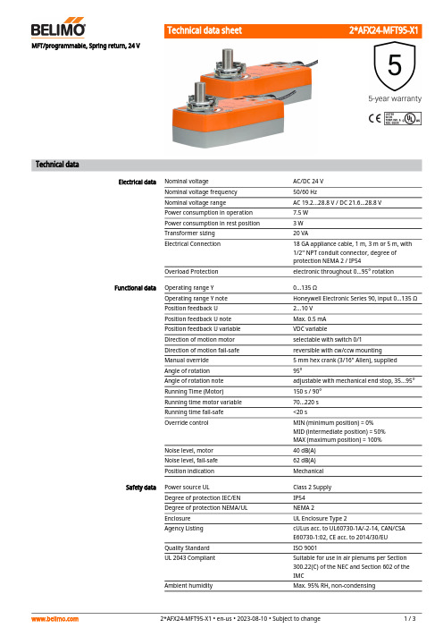
MFT/programmable, Spring return, 24 VTechnical dataElectrical data Nominal voltage AC/DC 24 VNominal voltage frequency50/60 HzNominal voltage range AC 19.2...28.8 V / DC 21.6...28.8 VPower consumption in operation7.5 WPower consumption in rest position 3 WTransformer sizing20 VAElectrical Connection18 GA appliance cable, 1 m, 3 m or 5 m, with1/2" NPT conduit connector, degree ofprotection NEMA 2 / IP54Overload Protection electronic throughout 0...95° rotationFunctional data Operating range Y0...135 ΩOperating range Y note Honeywell Electronic Series 90, input 0...135 ΩPosition feedback U 2...10 VPosition feedback U note Max. 0.5 mAPosition feedback U variable VDC variableDirection of motion motor selectable with switch 0/1Direction of motion fail-safe reversible with cw/ccw mountingManual override 5 mm hex crank (3/16" Allen), suppliedAngle of rotation95°Angle of rotation note adjustable with mechanical end stop, 35...95°Running Time (Motor)150 s / 90°Running time motor variable70...220 sRunning time fail-safe<20 sOverride control MIN (minimum position) = 0%MID (intermediate position) = 50%MAX (maximum position) = 100%Noise level, motor40 dB(A)Noise level, fail-safe62 dB(A)Position indication MechanicalSafety data Power source UL Class 2 SupplyDegree of protection IEC/EN IP54Degree of protection NEMA/UL NEMA 2Enclosure UL Enclosure Type 2Agency Listing cULus acc. to UL60730-1A/-2-14, CAN/CSAE60730-1:02, CE acc. to 2014/30/EUQuality Standard ISO 9001UL 2043 Compliant Suitable for use in air plenums per Section300.22(C) of the NEC and Section 602 of theIMCAmbient humidity Max. 95% RH, non-condensingFootnotesSafety dataAmbient temperature -22...122°F [-30...50°C]Storage temperature -40...176°F [-40...80°C]Servicingmaintenance-free Weight Weight[]MaterialsHousing material Galvanized steel and plastic housing*Variable when configured with MFT options.AccessoriesGatewaysDescriptionType Gateway MP to BACnet MS/TP UK24BAC Gateway MP to Modbus RTU UK24MOD Gateway MP to LonWorksUK24LON Electrical accessoriesDescriptionType Service tool, with ZIP-USB function, for programmable andcommunicative Belimo actuators, VAV controller and HVAC performance devicesZTH USToolsDescriptionTypeConnecting cable 10 ft [3 m], A: RJ11 6/4 ZTH EU, B: 3-pin Weidmüller and supply connectionZK4-GEN Service tool, with ZIP-USB function, for programmable and communicative Belimo actuators, VAV controller and HVAC performance devicesZTH USElectrical installationMeets cULus requirements without the need of an electrical ground connection.Provide overload protection and disconnect as required.Actuators may also be powered by DC 24 V.Actuators and controller must have separate transformers.Consult controller instruction data for more detailed information.Resistor value depends on the type of controller and the number of actuators. No resistor isused for one actuator. Honeywell® resistor kits may also be used.To reverse control rotation, use the reversing switch.Actuators may be controlled in parallel. Current draw and input impedance must be observed.Wiring diagrams High Limit ControlLow Limit ControlTypical and Override ControlMultiple ActuatorsMultiple Actuators with Minimum Position PotentiometerMultiple Actuators Used with W973, W7100 and T775。
流量控制阀数据表100496说明书

Close-off pressures are variable and actuator dependent, consult Select Pro and/or Price Guide for specifics.ApplicationThese valves are designed to meet the needs of HVAC and commercial applications requiring bubble tight shut-off for liquids. Typical applications include chiller isolation, cooling tower isolation, change-over systems, large air handler coil control, bypass and process control applications. The large Cv values provide for an economical control valve solution for larger flow applications. Designed for use in Victaulic® piping systems.Jobsite NoteValve assembly should be stored in a weather protected area prior toinstallation. Reference the butterfly valve installation instruction for additional information.SY4-6A B C D E F 25.2” [640]22.8” [579]29.4” [747]24.4” [620]15.7” [399]7.8” [199]F7200VIC Technical Data SheetPressure Enhanced Rubber SeatD a t e c r e a t e d , 01/13/2020 - S u b j e c t t o c h a n g e . © B e l i m o A i r c o n t r o l s (U S A ), I n c .ApplicationSY Series actuators are fractional horsepower devices, and utilize full-wavepower supplies. Observe wire sizing and transformer sizing requirements.Proportional models CANNOT be connected to Belimo direct coupled (AF,AM, GM…etc) actuator power supplies or any type of half-wave device. YouMUST use a separate, dedicated transformer or power supply to power the SYactuator. Please do not connect other automation equipment to the dedicatedSY supply source. You MUST use four wires (plus a ground) to control aproportional control SY actuator (See SY Wiring Section).SY4-24MFT Technical Data SheetModulating, Non-Spring Return, 24 V, for DC 2...10 V or 4...20 mADatecreated,12/2/219-Subjecttochange.©BelimoAircontrols(USA),Inc.60Do not change sensitivity or dip switch setting with power applied. 61Power supply Common/Neutral and Control Signal “-”wiring to a common is prohibited. Terminals 4 and 6 need to be wired separately.62Isolation relays must be used in parallel connection of multipleactuators using a common control signal inputs. The relays should be DPDT.63Isolation relays are required in parallel applications. The reason parallel applications need isolation relays is that the motor uses two sets of windings, one for each direction. When one is energized to turn the actuator in a specific direction a voltage is generated in the other due to the magnetic field created from the first. It’s called back EMF. This is not an issue with one actuator because the voltage generated in the second winding isn’t connected to anything so there is no flow. On parallel applications without isolation, this EMF voltage energizes the winding it is connected to on the other actuators in the system, the actuators are tying to turn in both directions at once. The EMF voltage is always less than the supply voltage due to the resistance of the windings, so while the actuator still turns in the commanded direction, the drag from the other reduces the torque output and causes overheating.!WARNING! LIVE ELECTRICAL COMPONENTS!During installation, testing, servicing and troubleshooting of this product, it may be necessary to work with live electrical components. Have a qualified licensed electrician or other individual who has been properly trained in handling live electrical components perform these tasks. Failure to follow all electrical safety precautions when exposed to live electrical components could result in death or serious injury.SY4-24MFT Technical Data SheetModulating, Non-Spring Return, 24 V, for DC 2...10 V or 4...20 mAD a t e c r e a t e d , 12/20/2019 - S u b j e c t t o c h a n g e . © B e l i m o A i r c o n t r o l s (U S A ), I n c .。
RF 浮动床控制阀安装、维护、使用手册说明书
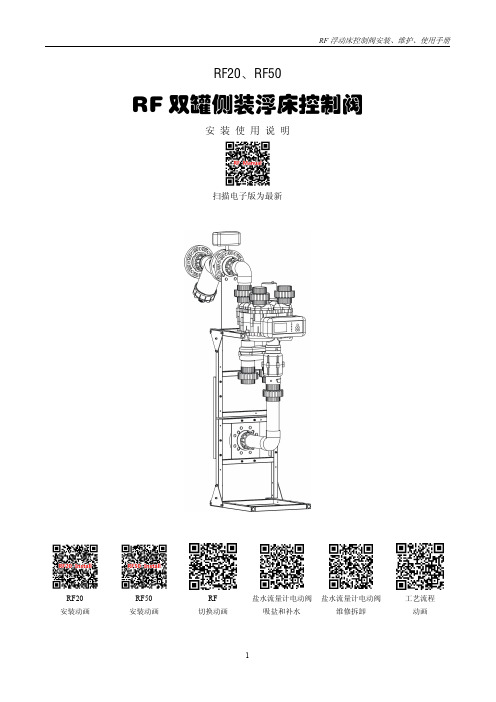
RF20、RF50RF 双罐侧装浮床控制阀安装使用说明扫描电子版为最新RF20安装动画RF50安装动画RF 切换动画盐水流量计电动阀吸盐和补水盐水流量计电动阀维修拆卸工艺流程动画一、控制器操作使用说明(1)RF控制器工位显示说明(2)RF控制器设定界面”和“”、在时间模式“示之间进行切换。
、多路阀切换到下一工位。
、屏幕出现参数设定界面,确认和退出G、:数字加二、安装1、内部管道安装:图1:RF20控制阀设备内部管道安装图2:RF50控制阀设备内部管道安装图3:RF控制器连线图图4:RF20控制阀软水器平面布局图5:RF20控制阀进出水、排污、供电系统设置和安装图6:RF50控制阀进出水、排污、供电系统设置和安装2、设备自动启停水箱液位控制A、控制器直接输出:当收到水箱上水位闭合信号时控制器控制进水电磁阀或电动阀关闭,控制器显示“水位已满”。
此输出为+12V有源信号,不能接入高压回路图7:RF20/RF50控制器输出液位控制图8:单节点浮球开关B、单接点水位开关、给水泵的联动控制图9:RF20外接单接点液位开关、给水泵联动接线图图10:RF50(进水电动阀)内部输出单接点软化水箱液位开关、给水泵接线盒C、附加继电器实现双接点水位开关、给水泵的联动控制RF软水器的水位控制为一个12V的有源接点,需要外界一个无源接点来控制,该接点闭合时,控制器停止工作,当水位开关采用上水位(常闭NC)下水位(常开NO)位的浮球开关时,需要一个小型继电器(如正泰HH54P/220VAC)进行转换。
图11:RF20/RF50内部输出双接点水位开关、给水泵联动接线图图12:双接点浮球开关3、设备安装注意事项1、进水安装过滤器,以免杂质进入电磁阀、多路阀、布水器。
2、应保证出水压力恒定,出水管道不安装阀门,软化水箱不安装浮球阀。
3、进水压力始终不低于设备高度,设备由地面水池水泵供水,进水管道安装止回阀,防止水泵停止设备水倒流。
AT Controls FD9-F6 Series 600# 直接装配分体流量阀门说明书

Cincinnati, Ohio FAX (513) 247-5462********************FD9-F6Series(B16.34)-20210708Copyright 2013 A-T Controls, Inc.ElectricPneumaticSERIES FD9-F6 600# Direct Mount Split Body Flanged Ball Valve FiresafeSee automated data sheets for pre-sized assembliesEasy to Automate!Triac FD9 Series Flanged Ball Valves feature a direct mount automation pad. The high quality investment castings feature a fully machined bore. The superior live-loaded packing system is accomplished with Belleville washers, “V” ring packing and a unique primary pyramidal stem seal. This advanced sealing system provides protection against stem leaks experienced by ordinary ball valves.available for seat materials. The 50/50 STFE seat option is excellent for services that call for higher temperatures and more difficult applications, including steam. Call us for details.C E R T I F I E D1Additional Special DesignationFD9C-F6-0200-CXXSee part number matrix for itemized optionsHOW TO ORDER MANUAL VALVESSAMPLE PART #Valve SeriesFiresafe End ConnectionCarbon SteelSeat MaterialValve SizeSpecial Designation Graphite Packing*FOR 1/2”-1-1/2” : 4 PCS. OF BOLTS AND NUTS *FOR 2” : 8 PCS. OF BOLTS AND BOLT NUTS $ FOR 1/2” - 1-1/2” : GRAPHITE$ FOR 2” - PTFE: TFM™-1600 GRAPHITE$$ ONLY PRESENT IN 2” DESIGNDIMENSIONS (IN)High Performance, Full Port600# Split Body Flanged Ball Valve Series FD9-F6 (ANSI Class 600)2FD9-F6Series(B16.34)-20210708 | Copyright 2013 A-T Controls, Inc. | | (513) 247-5465API 607 - 6th EditionC E R T I F I ED F I RE S AF EHigh Performance, Full Port600# Split Body Flanged Ball Valve2004006008001000120014001600-100-50050100150200250300350400450500550600P r e s s u r e (p s i )(°F)CTFE STFEPTFETFM-16003FD9-F6Series(B16.34)-20210708 | Copyright 2013 A-T Controls, Inc. | | (513) 247-5465600# FlangedFiresafe Tested to API-607Direct MountSERIES FD9-F6 600# Flanged Direct Mount FiresafeOther options available - call for detailsActuators are sized based on clean/clear fluid.API 607 - 6th EditionC E R T I F I E DSAMPLE PART #Valve SeriesValve Size Seat MaterialEnd ConnectionTRIAC Actuator SeriesActuator Size Double ActingSolenoidLimit SwitchFiresafe See valve part number matrix for complete part number and options.FD9-6C-100/2R3D-XXDIMENSIONS SHOWN ARE FOR ASSEMBLIES SIZED FOR 80 PSI SUPPLY4FD9-F6Series(B16.34)-20210708 | Copyright 2013 A-T Controls, Inc. | | (513) 247-5465DIMENSIONS (IN)Actuators are sized based on clean/clear fluid.DIMENSIONS SHOWN ARE FOR ASSEMBLIES SIZED FOR 80 PSI SUPPLYSAMPLE PART #Valve SeriesValve Size Seat MaterialEnd ConnectionTRIAC Actuator SeriesActuator Size Spring ReturnSolenoidLimit SwitchFiresafe See valve part number matrix for complete part number and options.FD9-6C-100/2R3S-XXSERIES FD9-F6 600# Flanged Direct Mount Firesafe600# FlangedFiresafe Tested to API-607Direct MountAPI 607 - 6th EditionC E R T I F I E D5FD9-F6Series(B16.34)-20210708 | Copyright 2013 A-T Controls, Inc. | | (513) 247-5465600# FlangedFiresafe Tested to API-607Direct MountSERIES FD9-F6 600# Flanged Direct Mount FiresafeOther options available - call for detailsActuators are sized based on clean/clear fluid.API 607 - 6th EditionC E R T I F I E DSAMPLE PART #Valve SeriesValve SizeSeat MaterialEnd ConnectionTRIAC Actuator SeriesActuator SizeOn-OffVoltageOptionsFiresafe See valve part number matrix for complete part number and options.FD9-6C-100/WEA1-XXDIMENSIONS (IN)DIMENSIONS SHOWN ARE FOR ASSEMBLIES SIZED FOR 80 PSI SUPPLY6FD9-F6Series(B16.34)-20210708 | Copyright 2013 A-T Controls, Inc. | | (513) 247-5465HOW TO ORDER:Manual ValvesChemraz® is a registered trademark of Greene, Tweed & Co.Markez® is a registered trademark of Marco Rubber & Plastic Products Inc.Perlast® is a registered trademark of Precision Polymer Engineering Limited.TFM™ is a trademark of Dyneon™, a 3M Company.FD9C-F6-0200-CXX-_ _ _SAMPLE PART #MANUAL VALVE(2) Valve Series (3) Body/Ball/Stem Material(5) Valve Size (6) Seat, Lining, & Trim Material (4) End Connection(7) Special Designation (8) Additional Specials(9,10,11) Options(1) Prefix7FD9-F6Series(B16.34)-20210708 | Copyright 2013 A-T Controls, Inc. | | (513) 247-5465HOW TO ORDER:Automated Valves w/ OptionsTFM™ is a trademark of Dyneon™, a 3M Company.(10) Special DesignationSAMPLE PART #(2) Valve Series(3) Body/Ball/StemMaterial(6) Valve Size(5) Seat, Lining & TrimMaterial(4) End Connection (7) TRIAC Actuator Series(7) Actuator Size (7) Double Acting(8) Accessory (9) Accessory AUTOMATED VAL VE FD9-6C-150/2R3D-XX-_(1) PrefixFD9-F6Series(B16.34)-20210708Copyright 2013 A-T Controls, Inc.9955 International Blvd.Cincinnati, Ohio PHONE (513) 247-5465FAX (513) 247-5462********************8。
控制阀F96说明书
控制阀F96说明书⽔处理系统⽤多功能控制阀53550(F96B1)53650(F96B3)63550(F96A1)63650(F96A3)73550(F96D1)73650(F96D3)93550(F96C1)93650(F96C3)安装使⽤说明书在使⽤本阀前请详读此说明书,并加以妥善保存以备今后参考之⽤。
0WRX.466.065正式投⼊使⽤前,请填写好下⾯的内容,以备后查程序型号设置(专业⼈员操作)秒,可进⼊型号选择界⾯。
设置型号时,须设置与控制阀体相应的型号。
软⽔器系统配置罐体尺⼨:直径mm,⾼度mm;填装树脂体积L;盐箱容积L;原⽔硬度mmol/L;进⽔压⼒MPa;控制阀型号;编号;排⽔限流圈规格;射流器型号。
进⽔⽔源情况(选择):地下⽔□;地下⽔加过滤器□;⾃来⽔□;其它。
控制阀设定参数●产品采购时,未作特殊说明:63550、63650、73550、73650配套的排⽔限流圈为4#(钻有5个φ8.5的孔),射流器型号为4#(7804)。
⽬录注意事项 (1)⼀、产品概述 (2)1、主要⽤途及适⽤范围 (2)2、产品特点 (2)3、使⽤条件 (5)4、产品结构及技术参数 (6)5、产品安装 (9)⼆、基本设置和使⽤说明 (16)1、控制⾯板功能及其意义 (16)2、基本设置和使⽤ (17)三、应⽤说明 (20)1、⼯作流程 (20)2、控制电路功能及连接 (22)A、信号输出端⼝ (23)B、互锁 (25)C、泄压端⼝ (26)D、远程控制端⼝ (26)E、双(多)阀,同时供⽔,分别再⽣ (26)F、双(多)阀单流量计,同时供⽔,顺序再⽣ (27)G、浮动床进⽔泵与软⽔泵 (27)3、产品系统配置及流量特性 (28)4、参数计算及取值 (32)5、参数查询和设置 (34)6、试运⾏ (38)7、常见故障及其排除⽅法 (40)8、组件及零部件编号 (43)四、保修说明 (52)●为确保产品安装后的正常使⽤,请在使⽤前让专业的安装或维修⼈员确认。
【F'A】电动调节阀说明书
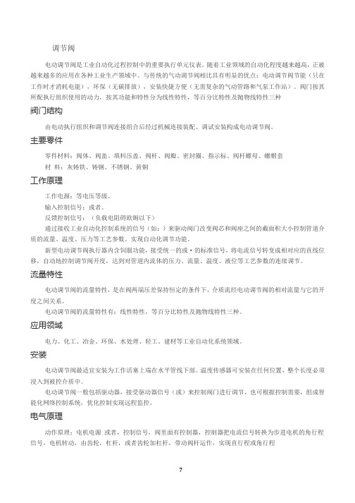
调节阀电动调节阀是工业自动化过程控制中的重要执行单元仪表。
随着工业领域的自动化程度越来越高,正被越来越多的应用在各种工业生产领域中。
与传统的气动调节阀相比具有明显的优点:电动调节阀节能(只在工作时才消耗电能),环保(无碳排放),安装快捷方便(无需复杂的气动管路和气泵工作站)。
阀门按其所配执行组织使用的动力,按其功能和特性分为线性特性,等百分比特性及抛物线特性三种阀门结构由电动执行组织和调节阀连接组合后经过机械连接装配、调试安装构成电动调节阀。
主要零件零件材料:阀体、阀盖、填料压盖、阀杆、阀瓣、密封圈、指示标、阀杆螺母、螺帽套材料:灰铸铁、铸钢、不锈钢、黄铜工作原理工作电源:等电压等级。
输入控制信号:或者。
反馈控制信号:(负载电阻碍欧姆以下)通过接收工业自动化控制系统的信号(如:)来驱动阀门改变阀芯和阀座之间的截面积大小控制管道介质的流量、温度、压力等工艺参数。
实现自动化调节功能。
新型电动调节阀执行器内含饲服功能,接受统一的或·的标准信号,将电流信号转变成相对应的直线位移,自动地控制调节阀开度,达到对管道内流体的压力、流量、温度、液位等工艺参数的连续调节。
流量特性电动调节阀的流量特性,是在阀两端压差保持恒定的条件下,介质流经电动调节阀的相对流量与它的开度之间关系。
电动调节阀的流量特性有:线性特性,等百分比特性及抛物线特性三种。
应用领域电力、化工、冶金、环保、水处理、轻工、建材等工业自动化系统领域。
安装电动调节阀最适宜安装为工作活塞上端在水平管线下部。
温度传感器可安装在任何位置,整个长度必须浸入到被控介质中。
电动调节阀一般包括驱动器,接受驱动器信号(或)来控制阀门进行调节,也可根据控制需要,组成智能化网络控制系统,优化控制实现远程监控。
电气原理动作原理:电机电源或者,控制信号,阀里面有控制器,控制器把电流信号转换为步进电机的角行程信号,电机转动,由齿轮,杠杆,或者齿轮加杠杆,带动阀杆运作,实现直行程或角行程反馈:电机运行,通过齿轮运转,由三接头的滑动变阻器输出阀门的定位信号,此外还有三根线的限位信号(全开,全闭。
- 1、下载文档前请自行甄别文档内容的完整性,平台不提供额外的编辑、内容补充、找答案等附加服务。
- 2、"仅部分预览"的文档,不可在线预览部分如存在完整性等问题,可反馈申请退款(可完整预览的文档不适用该条件!)。
- 3、如文档侵犯您的权益,请联系客服反馈,我们会尽快为您处理(人工客服工作时间:9:00-18:30)。
四种流量模式可任选(适用于 63650/73650/93650)
模式 名称
说明
出水流量达到设定流量且时间到达设定再生时间时 A-01 流量延滞型
引发再生或冲洗
A-02 流量即时型 出水流量达到设定流量时,立即引发再生或冲洗
可设定最大间隔再生天数(适用于 53650/63650/73650/93650)
远程控制输入
该端口可接收有源信号,与 PLC、电脑等配合使用,可远距离操作控 制阀。(应用见图 3-11) 带泄压端口
工位切换过程中信号开启,到位后信号关闭(相当于信号输出端口的 b-02)。主要用于采用增压泵供水的系统,电机切换时将进水管与控制阀间 的压力泄掉,以保证阀切换过程中水泵及控制阀的安全运行。(应用见图 3-10) 各参数可根据需要修改
单位 h:m
/ m3 D / min:sec min:sec min:sec min:sec min:sec min:sec min:sec D / /
出厂默认值 当前值 A-01 400.0 03 02:00 10:00 10:00 60:00 01:00 45:00 05:00 10:00 30 b-01 4.194
2、产品特点
结构简单密封可靠 采用高平面度、耐腐蚀的端面密封片启闭,密封可靠;集运行、反洗、
吸盐+慢洗、正洗和盐箱补水等软化全过程功能于一体。 单罐型控制阀再生时不出水
盐箱补水由电动球阀控制
盐箱补水由电动球阀控制,在运行的同时补水,缩短了再生周期。 在运行的同时补水,所以浮动床控制阀补的是软水,固定床控制阀补 的是硬水。
上电全屏图标全亮时,同时有效按“ ”键与“ ”键 2 秒以上,可 进入型号设置界面。按“ ”或“ ”键可选择所需要的型号,再按“ ” 键保存设置的型号。重新上电全屏亮后,再显示型号。 互锁功能
可实现多阀串联、并联或串并联使用的互锁系统(如反渗透预处理系 统等)中,最多只有一个阀在再生或冲洗,确保再生过程的正常运行。(应 用见图 3-9) 控制信号输出(针对 63650/63550/73620/73550 型号并加以妥善保存以备今后参考之用。 0WRX.466.065
MODEL 53550/53650/63550/63650/73550/73650/93550/93650
正式投入使用前,请填写好下面的内容,以备后查
程序型号设置(专业人员操作)
控制器上电全屏亮时,同时持续按下 和 5 秒,可进入型号选择界面。 设置型号时,须设置与控制阀体相应的型号。
1
MODEL 53550/53650/63550/63650/73550/73650/93550/93650
一、产品概述
1、主要用途及适用范围
主要用于水处理系统中进行软化、除盐或过滤水处理全过程的智能化控制。 53550/53650(过滤)
适用于泳池过滤设备 过滤系统 反渗透预处理系统中的活性炭过滤器、石英砂过滤器等 63550/63650(顺流再生软化) 73550/73650(逆流再生软化) 适用于原水硬度≤6.5mmol/L 的离子交换设备 锅炉给水软化系统 反渗透预处理系统中的软化系统等 93550/93650(浮动床软化) 适用于原水硬度<15mmol/L 的离子交换设备 锅炉给水软化系统 反渗透预处理系统中的软化系统等
目录
注意事项 .......................................................1 一、产品概述 ...................................................2 1、主要用途及适用范围 ..........................................2 2、产品特点 ....................................................2 3、使用条件 ....................................................5 4、产品结构及技术参数 ..........................................6 5、产品安装 ....................................................9 二、基本设置和使用说明 ........................................16 1、控制面板功能及其意义 .......................................16 2、基本设置和使用 .............................................17 三、应用说明 ..................................................20 1、工作流程 ...................................................20 2、控制电路功能及连接 .........................................22
当运行到了设定天数,流量还未到设定值时,当前时间与再生或冲洗 时间相同时强行进入再生或冲洗过程。
4
MODEL 53550/53650/63550/63650/73550/73650/93550/93650
3、使用条件 配套本控制阀的交换器的使用条件应符合下表中的要求:
项目
要求
工作压力 工作条件
进水温度
本阀带有信号输出端口,可用来控制外部线路。(应用见图 3-1 到 3-8) 程序内有两种输出控制模式。模式 b-01:程序在结束运行时信号开启, 到达运行时信号关闭;模式 b-02:程序在各转动位置时信号开启,到位后 信号关闭。如下图所示:
3
MODEL 53550/53650/63550/63650/73550/73650/93550/93650
间;原设定的其它参数停电后长期保存,无需重新设定,已进行的行程来 电后继续进行。 LED 彩色显示屏
彩条连续滚动表示处于运行状态,彩条不亮表示系统处于再生状态。 键盘锁定功能
一分钟内无按键操作,键盘自动锁定;再次操作前,需同时按“ ”、 “ ”键 5 秒钟将键盘解锁。该功能可有效防止误操作。 可通过程序更改型号
树脂呈红棕色或破碎,需及时更换。 使用过程中,应周期性的检测水质,以确保系统的正常运行。 该阀用于软化用途时,请确保在使用过程中盐罐内始终有固体盐。盐罐 内应加入纯度至少为 99.5%的晶块状粗盐,严禁使用细盐。 切勿将阀门靠近热源或高湿度、有腐蚀性、强磁场、强振动等环境中, 亦不能将其直接暴露于室外。 严禁扳动射流器体,避免将射流器体用作把手或用力支点。 严禁将吸盐管和其它接头作为支承提升或搬运系统。 请在水温为 5~50℃、水压为 0.2~0.6MPa 范围内使用本产品,在此范 围外使用本品所引发的故障或事故不在本公司责任及保修之列。 如果进水压力大于 0.6Mpa,须在进水口端安装减压阀;进水压力低于 0.2MPa 时,应在进水端加装增压泵。 管道安装建议使用 PPR 管、波纹管或 UPVC 管,避免使用铝塑管。管路安 装应平直。 切勿让儿童接触或玩耍,不小心碰到操作键可能导致程序发生变化。 本产品附带的电源线及电源适配器损坏时,必须更换本公司出厂的电源 线及电源适配器。
顺/逆流软化阀可改成过滤阀 63550/73550/63650/73650 封堵吸盐口,去掉排水接头,可用于过滤系
统。
手动功能 可即时按下“ ”键实现强制再生。
2
MODEL 53550/53650/63550/63650/73550/73650/93550/93650
停(断)电参数保护及提示 停电超过 3 天,来电后时钟数据“12:12”将持续闪烁,须重设当前时
I
MODEL 53520/53620/63520/63620/73520/73620/93520/93620
注意事项
● 为确保产品安装后的正常使用,请在使用前让专业的安装或维修人员确 认。 安装时如有任何管道工程及任何电器工作都必须由专业人员完成。 严禁将该阀用于不安全的或者不明水质的地方。 软化各过程的参数应根据工作条件的变化和出水的要求及时修正。 当周期制水量过低时,请检查树脂的状况。如果树脂量过少需补加;如
0.2MPa~0.6MPa 5℃~50℃
环境温度 5℃~50℃
工作环境 相对湿度 ≤95%(25℃时)
软水器系统配置
罐体尺寸:直径
mm,高度
mm;
填装树脂体积
L;盐箱容积
L;
原水硬度
mmol/L;进水压力
MPa;
控制阀型号
;编号
;
排水限流圈规格
;射流器型号
。
进水水源情况(选择):地下水 □;地下水加过滤器 □;
自来水 □;其它
。
控制阀设定参数
参数 当前时间 控制模式 A-01/02(流量型) 周期制水量(流量型) 运行天数(时间型按天计) 再生引发时间 落床时间(F96C1/3 具有) 反洗时间(F96A/B/D 具有) 吸盐时间(F96A/C/D 具有) 浸泡时间(F96C1/3 具有) 慢洗时间(F96C1/3 具有) 补水时间(F96A/C/D 具有) 正洗时间 最大间隔再生天数(时间型无) 输出控制模式 b-01/2(F96C 无) K 值(流量型具有)
中国专利号:ZL02220153.X, ZL200720045551.5
水处理系统用多功能控制阀
53550(F96B1) 53650(F96B3) 63550(F96A1) 63650(F96A3) 73550(F96D1) 73650(F96D3) 93550(F96C1) 93650(F96C3)
A、信号输出端口 ...........................................23 B、互锁 ...................................................25 C、泄压端口 ...............................................26 D、远程控制端口 ...........................................26 E、双(多)阀,同时供水,分别再生 ......................... 26 F、双(多)阀单流量计,同时供水,顺序再生 ................. 27 G、浮动床进水泵与软水泵 ...................................27 3、产品系统配置及流量特性 .....................................28 4、参数计算及取值 .............................................32 5、参数查询和设置 .............................................34 6、试运行 .....................................................38 7、常见故障及其排除方法 .......................................40 8、组件及零部件编号 ...........................................43 四、保修说明 ..................................................52