水力控制阀说明书
Parker Hannifin 水力卡片系统阀门系统手册说明书

Contents
SERIES
CAVITY
Shuttle Valves
DESCRIPTION
FLOW PRESSURE LPM/GPM BAR/PSI
CV PAGE NO.
Check Valves
KSWA3 ............. SW-3 ........... Ball Insert Type .............................................. 9.5/2.5 ...... 420/6000 ..................... SH3 K2A005 ............. 3Z ............... Poppet Insert Type .......................................... 38/10 ...... 350/5000 ..................... SH4 SH
(2)
(3)
Outlet Inlet
(1) Inlet
Flow Controls
Pressure Controls
PC
Poppet Type - Insert Style
(2) Out
This shuttle performs the same
function, but allows for higher flow
K3A125 ............. 3U ............... Spool Type, Spring Centered, .............................................. All Ports Closed ............................................. 175/46 ...... 350/5000 ................... SH13
戴尼森水力控制器R5型号产品说明说明书

Publ.3–EN 2900–C (dig.)DENISON HYDRAULICSPressure Controls –Flanged TypeSeries R5with 3portsFEATURES,SYMBOLSYMBOLR5VR5V06pilot valveR5V08/10/12pilot valveY1(optional)Y1(optional)BAMExample:R5V Pressure Relief ValveFEATURESxIncrease Operating Satefy:Flange mounted valves as illustrated in this bulletin increase operating safety and reduce mounting costs.The R5range of flange bodied pressure controls enable the valves to be mounted directly on an SAE pump outlet flange,ensuring maximum pump protection against peak pressure and eliminating costly piping.xHigh Performance:R5valves are designed for a maximum adjustable pressure up to 350bar and a flow capacity ranging from 90l/min (3⁄4HH )to 600l/min (11⁄4HH and 11⁄2HH ).The pilot stage design reduces pressure overshoot and cracking flow to a minimum,thus reducing power and production losses during high pressure operation.xPrecise Control:With the DENISON combined Seat Valve and Pilot design,and the range of springs available,it is possible to achieve extremely precise pressure setting.xFast Response:The favourable poppet mass to area ratio is especially advanta-geous,as it enables such features as fast response,high accuracy and quiet,flutter free control.xWide Selection:In addition to the three port flange mount valve,the ordering code offers a wide range of control options for valves and accessories.DESCRIPTIONGENERALDESCRIPTIONDENISON Pressure Valves are pilot operated controls consisting of two or three valve sections,either a high flow,poppet type seat valve section controlled by the low flow,adjustable pilot mounted on top or in the case of the Proportional Pressure Relief Valve,the proportional section P2sandwiched between the pilot valve and the main body.Pressure setting is achieved by means of a knurled knob or,if a tamperproof setting is required,by an acorn nut with lead seal.A proportional pressure setting is achieved according to the current input by R5V (2)PRESSURE RELIEF VALVER5V pressure relief valves are used to limit the system pressure of a hydraulic system,in order to control the force exerted by a hydraulic actuator.The R5V valve may also be used to generate a pressure drop in a hydraulic circuit.Normally the pump is connected to Port A and the tank line to Port B.PRESSURE UNLOADING VALVEAccumulator system with Unloading Valve R5UR5U pressure unloading valves are used to unload a circuit at low pressure when a port signal (Port X1)is maintained at a pressure that is higher than that of the pilot section.A typical application for an R5U is to unload a pump that is connected to an accumulator circuit.Another use for the R5U is to unload the low pressure side of a double pump.In applications with an accumulator,it should be noted that the R5U and its accom-panying check valve should be mounted as close to the accumulator as possible.This will prevent that the …p,caused by long feed lines between the R5U and the accumulator,will reduce the selected 15or 28%pressure differential (prevention of switching oscillations).SEQUENCE VALVEThe R5S valve enables a hydraulic system to operate in a pressure sequence.After system pressure connected to Port A has reached a preadjusted value,fluid is allowed to pass through Port B to a secondary system.NOTEDENISON flange valves enable the realisation of complete control systems.In addition to the valves discussed in this publication,the following flange valves are also available:Publication–R5pressure valves with 2ports 3–EN 2850–F5C flow controls &R5A,R5P compensators 5–EN 4200–C5V check valves,direct operated 6–EN 4660–C5P check valves,direct &pilot operated 6–EN 4700–D5S seat valves with 2ports 7–EN 520–D5S seat valves with 3ports 7–EN 530setting pressuremin.operating pressureswitching difference 15%or 28%When the system pres-sure (in an accumulator for example)has fallen 15%or 28%below the pilot setting,the valve will close,and the pump flow will be restored to the hydraulic system.R5U..–..1/3=28%R5U..–..5=15%Note:The mentioned switching difference values are theoretical and can vary between 12...15%,respectively between 20...28%.TECHNICAL DATAGENERAL x Design Poppet typex Type of mounting Flanged according to SAE-61e.g.directly on a pump(R5V12according to SAE-62)x Port sizes3⁄4HH,1HH,11⁄4HH,11⁄2HH(only R5V,R5U)x Mounting position Optionalx Direction of flow A f Bx Ambient temperature range–20...+60h Cx Suitability for special Consult DENISONworking conditionsHYDRAULIC CHARACTERISTICS x Operating pressure–Inlet(Port A)...350bar R5*06/08...350bar R5V12(SAE62)...280bar R5*10...210bar R5U(V)12(SAE61)–Outlet(Port B)...30bar R5U,R5V...210,280,350bar R5S,R5U,R5VR5S:p at B<at A–Port X...210,280,350bar–Ports Y,Y1...30barx Pressure setting range–min≥3bar–max210,280,350barR5*06R5*08R5*10R5V,R5U123⁄4HH1HH11⁄4HH11⁄2HHx Max.flow90l/min300l/min600l/min600l/minx Nominal flow depends on pump deliveryx Fluid Mineral oil according to DIN51524/25(other fluids on request)x Contamination level Max.permissible contamination levelaccording to NAS1638Class8(Class9for15Micron and smaller)or ISO17/14x Fluid temperature range–18...+80h Cx Viscosity range10...650cSt;optimal30cStTYPE OF ACTUATOR x Manualx Rotation 3.75x360hx Operation torque72Ncmx Electric By solenoidx Nominal voltage Refer to ordering code page5x Permissible voltage difference+5% (10)x Max.coil temperature+180h C(temperature class H)x Type of current Alternating current(AC)or direct current(DC)x Input power31Wx Holding78VAx Inrush264VAx Relative operating period100%x Type of protection IP65x Electric proportional0...2.5A(Pilot stage P2)(refer to publication3–EN2200)ORDERING CODEomit for version without VV01&without P2Model NumberR5.............A1––––––SeriesR5V =Pressure Relief ValveR5U =Pressure Unloading Valve R5S =Sequence Valve Size 06=3⁄4HH08=1HH 10=11⁄4HH12=11⁄2HH (R5V,R5U only)Max.Pressure 3=210bar –SAE 61flange (R5V/R5U12)4=280bar –SAE 61flange (R5.10)5=350bar –SAE 61flange (R5.06/08)6=350bar –SAE62flange(R5V12only)BodyPorts X12),Y 11),M 2)3=SAE-4(7⁄16HH –20UNF)9=G 1⁄4HH1)Port Y1is only available at external PD (codes 4&6)from the pilot head 2)closed when suppliedPressure Setting Range1=...105bar (R5U:Pressure differential 28%)3=...210bar (R5U:Pressure differential 28%)5=...350bar (R5U:Pressure differential 15%)Type of Control1=Hand knob 32mm dia.2=Hand knob 50mm dia.(not for version with vent valve VV01or P2)3=Acorn nut with lead seal4=Adjusting device with key lock (key order no.700–70619–8)Pilot Connection2=Internal PD –internal PP (R5V)4=External PD –external PP*(R5U)5=Internal PD –external PP*(R5U)6=External PD –internal PP (R5V,R5S)*External pilot pressure connection on flange face (port X2)3-Way Vent Valve VV0109=with manual override Solenoid de-energized:open to tank 10=without manual override Solenoid energized:vent line blocked 11=with manual override Solenoid de-energized:vent line blocked 12=without manual overrideSolenoid energized:open to tankk kP2=Electric Proportional Pressure Control (12V DC only,R5V only)Solenoid Voltage and CurrentW01=115V /60Hz 1)G0R =12V W02=230V /60HzG0Q =24V DC W06=115V /50Hz ACG0H =48VW07=230V /50Hz1)R5V....P2=12V DC onlykkDesign LetterSeal Class1=NBR (Buna N)Standard 4=EPDM5=VITON `Modifications12345678 0123912345678910111213p-Q-CURVESP r e s s u r e (b a r )P r e s s u r e (b a r )Flow (l/min)Flow (l/min)R5V06R5V08n o m i n a l f l o wn o m i n a l f l o wMin.pressure setting ≥4bar(depending on flow and viscosity).Fluid 40cSt and 50h C ±0.5h C.P r e s s u r e (b a r )Flow (l/min)R5V10/12n o m i n a l f l o wUnloading Function free flow P -T R5U06Flow Q /l/minR5U08Flow Q /l/minR5U10/12Flow Q /l/minOverrided Pressure Relief Function R5U06Flow Q /l/minR5U08Flow Q /l/minR5U10/12Flow Q /l/minMin.pressure setting ≥4bar(depending on flow and viscosity).Fluid 40cSt and 50˜C ±0.5˜C.P r e s s u r e d r o p …p /b a rP r e s s u r e d r o p …p /b a rP r e s s u r e d r o p …p /b a rP r e s s u r e p /b a rP r e s s u r e p /b a rP r e s s u r e p /b a rn o m i n a l f l o wn o m i n a l f l o wn o m i n a l f l o wn o m i n a l f l o wn o m i n a l f l o w n o m i n a l f l o w3⁄8HH UNC x20lg.for R5U only(3.0dia.,only on R5U)external pilot pressure port available for usewith C5V check valvePorts Function Port sizes R5V R5U R5SA(2x)Pressure3⁄4HH(SAE-61)x x xB Tank2)3⁄4HH(SAE-61)x x xX1ext.pilot port1)G1⁄4HH or SAE-4xY1ext.drain G1⁄4HH or SAE-4x x xM Pressure gauge G1⁄4HH or SAE-4x x x1)closed when supplied2)secondary port on R5SNote:R5*06pressure controls are mounted directly on the”B”cartridge of DENISON vane pumpsand axial piston pumps PVT6.3⁄8HH UNC x23lg.for R5U only(3.0dia.,only on R5U)external pilot pressure port available for usewith C5V check valvePorts Function Port sizes R5V R5U R5SA(2x)Pressure1HH(SAE-61)x x xB Tank2)1HH(SAE-61)x x xX1ext.pilot port1)G1⁄4HH or SAE-4xY1ext.drain G1⁄4HH or SAE-4x x xM Pressure gauge G1⁄4HH or SAE-4x x x1)closed when supplied2)secondary port on R5SNote:R5*08pressure controls are mounted directly on the”C”cartridge of DENISON vane pumpsand axial piston pumps PVT10...29.7⁄16HH UNC x22lg.for R5U only(3.0dia.,only on R5U)external pilot pressure port available for usewith C5V check valvePorts Function Port sizes R5V R5U R5SA(2x)Pressure11⁄4HH(SAE-61)x x xB Tank2)11⁄4HH(SAE-61)x x xX1ext.pilot port1)G1⁄4HH or SAE-4xY1ext.drain G1⁄4HH or SAE-4x x xM Pressure gauge G1⁄4HH or SAE-4x x x1)closed when supplied2)secondary port on R5SNote:R5*10pressure controls are mounted directly on the”D”cartridge of DENISON vane pumps.R5V 12–R5U 12(11⁄2HH )Weight:8kgd 2x l 2for R5U only(3.0dia.,only on R5U)external pilot pressure port available for use with C5V check valvePorts Function Port sizes R5V R5U A (2x)Pressure 11⁄2HH (SAE-61/62)x x B Tank11⁄2HH (SAE-61/62)x x X1ext.pilot port 1)G 1⁄4HH or SAE-4x Y1ext.drain G 1⁄4HH or SAE-4x x MPressure gaugeG 1⁄4HH or SAE-4xx1)closed when suppliedNotes–R5*123–SAE 61mounted directly on the ”E”cartride of DENISON vane pumps.–R5V126–SAE 62mounted directly on the DENISON axial piston pumps series ”World-Cup”and ”Premier”.l 1l 2b 1d 1d 2R5*123SAE 6169.82735.713.51⁄2HH –13UNC R5V126SAE 6279.43336.5175⁄8HH –11UNCADDITIONAL TYPES OF CONTROLS,SYMBOLSADDITIONAL TYPES OF CONTROLSType of Control-Code 2Hand knob 50mm dia.(not for version with vent valve VV01or P2)Type of Control-code 3Acorn nut with lead sealType of Control-Code 4Adjusting device with key lock.Key must be ordered separately order-no.700–70619–8SYMBOLSInternal External Drain DrainPressure Relief Valve R5VPressure Unloading Valve R5USequence Valve R5SX1or X2X1or X2VERSION WITH VENT VALVE VV01Weight (VV01):1.7kgScrews for additional vent valve installation.4x 3⁄8HH –24UNF x 31⁄2HHlg.,order no.359–15340–0.Vent valveVV01Pilot valveY1Main valveManual overridePlug-in connector DIN 43650(supplied as standard)Solenoid can be turned:–through 90h intervals (AC)–in any position (DC)AC Ù149DC =160Note:Details for vent valve VV01see publication 3–EN 215.Symbols:R5*–Pressure Controls with Vent Valve VV01Pressure Relief ValvePressure Unloading ValveSequence ValveR5V R5U R5SCodeInternal External Internal External External DrainDrainDrainDrainDrain11or 1209or 10X1or X2X1or X2X1or X2X1or X2P ROP ORTIONAL P RESSURE RELIEF VALVE R5V...P2 Screws for additional proportional section installation4x3⁄8HH–24UNF x31⁄2HH lg.,Order No.359–15340–0.Pilot ValveProportionalsection P2(weight1.8kg)Main valve body (see pages7...10)Coil can be placed in any positionDrain lineOnly external from the pilothead(Y1).The pilot drain port must beconnected to a stable low pressuretank line.Pressure variations inthe drain port should be avoided.Distance required to removeplug-in connector.Plug-in connector suppliedas standard.Important:On initial start upand after long shut down periodsbleed air from thisplug. SymbolNote:See publication3–EN2200for information on Electrical Proportional Control Valve.For additional installation with pilot operated control valves please consult DENISON.SAE-FLANGESwith G-thread socket weldwith G-thread socket weldInlet flange (only forpipe mounting)available withUNC-threads onlyOutlet and tank port flangeInlet flange Outlet flange Tank port (without screws*)(without screws*)flange only for (with screws)pipe mounting Port sizes d 1Order No.Order No.Order No.l 1l 2b 1b 2b 3h 1h 2d 2l d 3l d 4l d 5G 3⁄4HH 1)3⁄4HHsocket weld S16–86520–0S16–86529–0S14–66933–0S16–86519–0S16–86528–0S14–66941–06747.63415.92222.2524016.51912–––10.53⁄8HHUNCG 1HH 1)1HH socket weld S16–86523–0S16–86532–0S14–66934–0S16–86522–0S16–86531–0S14–66942–07252.434202226.2584616.52414–––G 11⁄4HH 1)11⁄4HH socket weldS16–86526–0S16–86535–0S14–66935–0S16–86525–0S16–86534–0S14–66943–08058.739222430.2735417.52414–––12.57⁄16HHUNCG 11⁄2HH 1)11⁄2HH socket weldS26–52364–0S26–52215–0S14–66936–0S26–52366–0S26–52217–0S14–66944–09469.839242435.78260202616–––14.51⁄2HHUNCG 11⁄2HH 2)11⁄2HH socket weld464–01147–0464–01141–0464–01004–0464–01149–0464–01143–0464–01146–011279.450283036.594602517.55⁄8HHUNC1)SAE 612)SAE 62*see pages 15and 16for screwsExampleValves Group B R5*,F5C,C5P,D5S Valve Group AC5VPump or Motor Thigtening torque:28...40Nm for3⁄4HH valves 37...48Nm for1HH valves 48...62Nm for11⁄4HH valves 62...70Nm for11⁄2HH valvesInlet flange forpipe mounting(with threads for bolts)Socket weldQty.of valvesand group for UNC-Screws(12.9)Metric Screws(12.9) each stack l1l2Dimension Order No.Dimension Order No.1x A453⁄8HH–16x31⁄4HH358–16330–0M10x80361–11324–8 1x B603⁄8HH–16x33⁄4HH358–16350–0M10x95361–11354–83⁄4HH(1x A)+(1x B)10516...223⁄8HH–16x51⁄2HH358–16420–0M10x140361–11424–8SAE612x B1203⁄8HH–16x6HH358–16440–0M10x160700–70836–8 (1x A)+(2x B)1653⁄8HH–16x8HH358–16520–0M10x200700–70821–8 3x B1803⁄8HH–16x81⁄2HH358–16540–0M10x220361–11494–81x A453⁄8HH–16x31⁄4HH358–16330–0M10x80361–11324–81x B603⁄8HH–16x33⁄4HH358–16350–0M10x95361–11354–81HH(1x A)+(1x B)10518...243⁄8HH–16x53⁄4HH358–16430–0M10x140361–11424–8SAE612x B1203⁄8HH–16x61⁄4HH358–16450–0M10x160700–70836–8 (1x A)+(2x B)1653⁄8HH–16x8HH358–16520–0M10x200700–70821–8 3x B1803⁄8HH–16x81⁄2HH358–16540–0M10x220361–11494–81x A507⁄16HH–14x31⁄2HH358–18340–0M12x90361–12344–81x B757⁄16HH–14x41⁄2HH358–18380–0M12x120361–12404–811⁄4HH(1x A)+(1x B)12521...257⁄16HH–14x61⁄2HH358–18460–0M12x170361–12454–8SAE612x B1507⁄16HH–14x71⁄2HH358–18500–0M12x190361–12474–8 (1x A)+(2x B)2007⁄16HH–14x91⁄2HH358–18580–0M12x240361–12504–8 3x B2257⁄16HH–14x101⁄2HH358–18590–0M12x270361–12664–81x A501⁄2HH–13x33⁄4HH358–20350–0M12x90361–12344–81x B801⁄2HH–13x5HH358–20400–0M12x130361–12414–811⁄2HH(1x A)+(1x B)13025...271⁄2HH–13x63⁄4HH358–20470–0M12x170361–12454–8SAE612x B1601⁄2HH–13x8HH358–20520–0M12x200361–12484–8 (1x A)+(2x B)2101⁄2HH–13x10HH358–20600–0M12x250361–12674–8 3x B2401⁄2HH–13x111⁄4HH358–20650–0M12x290361–12684–8Nominal UNC-Screws (12.9)Metric Screws (12.9)Series Size l1l2Dimension Order No.Dimension Order No.R5V12–611/2HH 80305/8HH -11x 51/4HH 358-24410-0M16x 130361-14414-8C5V1211/2HH 50305/8HH -11x 4HH 358-24360-0M16x 100361-14364-8R5V12–6+C5V1211/2HH130305/8HH -11x 7HH358-24480-0M16x 180361-14464-8Pump or MotorSAE 62FlangeR5V12–6C5VThigtening torque:158...181NmThe product described is subject to continual development and the manufacturer reserves the right to change the specifications without notice.。
Parker 7321B 7322B 水控制双向双位操纵阀门说明书

climate control electromechanical filtrationfluid & gas handling hydraulics pneumatics process controlsealing & shieldingParker 7321B/7322B Series Water ValvesParker 7321B/7322B 2/2 pilot operated valvesis the best solution anywhere a perfect controlmedia such water, steam, and light oils isrequired.7321B/7322B Series are diaphragm pilot operatedvalves and require a minimum diff erentialpressure to operate.Water is the basic element for human life,and water control makes possible a widevarety of human activities such asirrigation and food production, breeding,water dispensing, energy production,car and tools washing; water is the basicelement in many applications likefi re-fi ghting, domotic, plumbing.Basing on solenoid technology, amongthe features this product provides a high fl ow rate,a fast reaction time and a superior reliabilityin a robust and modern design.Manual override is available to open andclose the valve without electrical supply,as well as speed control option againstwater hammer eff ect.Our 7321B/7322B Water Valvesrange is usable with the most ofour FCDE coil ranges, includingATEX, low power and IP67electrical parts.The Species EvolutionApplicationsBenefi tsTh anks to the best performances in fl ow rate,7321B/7322B Series can be used for many applications with high fl ow rates and media such as water, hot water and steam. Typical applications can be found in: Plumbing mkt, industrial washing machines,car wash installations, cooling of machine tools, hydrocleaners, autoclaves, irrigation systems, etc…Among the most valuable features you can fi nd in this product:● Best performances for minimum and maximumoperating pressure diff erential● Exclusive diaphragm design for a Superior Flow Rate ,higher than the competition valves with the same dimensional specs and fl at diaphragm● One of the Fastest in electrical and hydraulic openingresponse time● Modular concept: a wide range of electrical partsincreases the versatility of this product● Robust design: areas under mechanical stress have beenstudied and oversized● Manual override control option: valve can be easilyactivated also when there’s no energy supply● Stainless steel pilot for superior life endurance withspe c ial sealing● Easy access to internal parts, to permit easy and quickmaintenan c eIntroducing Parker 7321B/7322B Series Water ValvesPlease consult factory in case you need to verify the compatibility of 7321B/7322B Series with alternative ranges of paper FCDE coils not inclused in this catalogue.Parker 7321B/7322B are diaphragm pilot operated solenoid valves and require a minimum differential pressure to operate.This serie is available in both Normally Closed and Normally Open function: 7321B Serie is a Normally Closed family (closed when de-energised), 7322B Serie is the Normally Open family (Open when de-energised).General DescriptionValve body: CW617N UNI EN 12165:98 Forged Brass Enclosing tube: AISI 304 stainless steel Plunger:AISI 430F St. SteelSpring:AISI 302 St. SteelSeals: NBR (Buna N) - EPDMFK M (Viton)Shading ring: CopperMaterial Specifi cationsThe valves can be mounted in any position. It is however recommended to install them with the coilin vertical position above the body.InstallationThese valves have been developed to achieve the best performances for water, steam, light oils (up to 2°E). Therefore these valves are not usable with gas and air.We recommend to choose NBR versions for plumbing mkt (max. temp. 90°C), FKM version for water/light oils control applications up to 140°C, EPDM version for superheated water and steam (up to 140°C)MediaA wide range of electrical parts are available for 7321B/7322B Series. The complete offer of electrical parts is shown at pages 20 to 23.Electrical PartsClosedOpenOpenClosed Available OptionsParker 7321B Serie (NC version only) can be ordered with Manual control option. A manual control is used to operate the valve without connecting the coil.The control consists in a slotted-head screw for a screwdriver and has two possible positions:Closed: The letter "C" is in the upper position of the screw head (fi g.1,2)Open: The letter "A" is in the upper position of the screw head (fi g.1,2)Standing in its closed position, the valve operates normally when coil is energised/de-energised. Manual and speed control are standard on 2 ½" and 3" versions.Manual ControlParker 7321B Serie (NC version only) can be ordered with Speed control option. The closure time of certain types can be changed by means of the adjusting screw. The latter, by acting as a throttle on the inlet equalisation (pilot) hole of the valve, slows down the closure speed of the valve, thus reducing the water hammer effect.The regulation range is as follows: Screw fully open: Max. closure speed Screw fully closed: Valve always openSpeed Control Option (Anti-Water Hammer Control)123456810203040506080100Sec.bar3"123456810203040506080100Sec.bar3/4" - 1"123456810203040506080100Sec.bar2 1/2"123456810203040506080100Sec.bar 2"123456810203040506080100Sec.bar1 1/4" - 1 1/2"Diagrams of the Closing Times-----Product availability7321B/7322B Pressure VesselA wide range of confi gurations for this solenoid valve family is available: port sizes from 3/8" to 3" in brass, with BSPP port threads or with NPT ports, along with a wide range of seal and disc materials ensures that we have a standard valve to fi t most applications.In the table herebelow you might also fi nd an explanation of the general description system for 7321B/7322B Series water valves family.Please note:- Electrical parts available are not included in the description system hereabove which refers to pressure vessel only. You can fi nd electrical parts available at pages 20 to 23. DescriptionReference7 3 2 1 B A N x x 7 7 000 Operators 3 Pilot Operated Valve 2 Direct L ift Operated Valve 1 Direct Operated Valve 2 2/2 Ways 2 Normally Open 1 Normally Close A Family Name B C… I 3/8" A 1/2" C 3/4" D 1" E 1 1/4" F 1 1/2" G 2" L 2 1/2" M 3" N NBR V KKM H EPDM 0 0 Standard Version 0 1 Manuel Override 0 2 Speed Control + MO 0 6 Speed Control 9 0 NPT 9 1 NPT - Manuel Override (MO)9 2 NPT - Speed Control + MOS x x x Special versions2/2 Normally Closed - BSPP threadsNBR Seals(Max. Media Temp. 90°C)Nominal pressure: 25 bar from 1 ¼" to 3" 16 barFKM Seals (Max. Media Temp. 140°C)Nominal pressure:25 barEPDM Seals (Max. Media Temp. 140°C)Dimensional Drawing N° 2Dimensional Drawing N° 36940407299.5101.544443/8" G1/2" G3/4" G10065441072/2 Normally Closed - BSPP threadsDimensional Drawing N° 5Dimensional Drawing N° 610414514565102102112.51341344444441" G1 1/4" G1 1/2" GDimensional Drawing N° 8Dimensional Drawing N° 9173118148442"2451841952 1/2" G442501841953" G442/2 Normally Open - BSPP threadsNBR Seals (Max. Media Temp. 90°C)Nominal pressure:25 bar from 1 ¼" to 3" 16 barFKM Seals(Max. Media Temp. 140°C)Nominal pressure: 25 bar from 1 ¼" to 2" 16 barEPDM Seals (Max. Media Temp. 140°C)Nominal pressure:25 bar from 1 ¼" to 2" 16 barDimensional Drawing N° 11Dimensional Drawing N° 126940407211011244443/8" G1/2" G3/4" G10065441072/2 Normally Open - BSPP threadsDimensional Drawing N° 14Dimensional Drawing N° 1510414514565102102123144.5144.54444441" G1 1/4" G1 1/2" GDimensional Drawing N° 17Dimensional Drawing N° 18173118158.5442"245184205.52 1/2" G44250184205.53" G442/2 Normally Closed - NPT threads2/2 Normally Open - NPT threadsNBR Seals (Max. Media Temp. 90°C)Nominal pressure:25 bar/360 PSI from 1 ¼" to 2" 16 bar/230 PSIEPDM Seals (Max. Media Temp. 140°C)Nominal pressure:25 bar/360 PSINBR Seals(Max. Media Temp. 90°C)EPDM Seals(Max. Media Temp. 140°C)Dimensional Drawing N° 20Dimensional Drawing N° 212.71 1.571.572.833.913.991.731.733/8" N P T1/2" N P T3/4" N P T3.93 2.551.734.212/2 Normally Closed / Normally Open NPT threadsDimensional Drawing N° 23Dimensional Drawing N° 244.095.705.70 2.554.014.014.425.275.271.731.731.731" N P T1 1/4" N P T1 1/2" N P TDimensional Drawing N° 266.81 4.645.821.732"NPTElectrical parts availabilityStandard Coil Mono-Frequency, F class, IP65 with Connector Encapsulated in synthetic material, Connector for 2P + E DIN 43650 A Plug.Standard Coil Bi-Frequency, F class, IP65 with Connector Encapsulated in synthetic material, Connector for 2P + E DIN 43650 A Plug.UL approved Coil, F classEncapsulated in synthetic material, Connector for 2P + E DIN 43650 A Plug.H class Coil, IP65 with Connector(DC, AC 14W) encapsulated in synthetic material. Connection for 2P + E DIN 43650 A plug.Dimensional Drawing N° 27All quotes are in mmDimensional Drawing N° 2818.837,520322435.519.552325500 ± 5 cable38Electrical parts availabilityIP67 Coil with two 500 mm fl ying leads, F classEncapsulated in synthetic material. Protection rate IP67 as per DIN 40050.Connection: 2 x 500 mm cablesIP67 coil with two 500 mm fl ying leads, F class, UL approved Encapsulated in synthetic material. Protection rate IP67 as per DIN 40050.Connection: 2 x 500 mm cablesExplosion-proof EEx m II T4 (IP65)Coil with housing integrated. Coil and magnetic circuit encapsulated in synthetic material.The complete housing is supplied with an encapsulated connection cable (3 x 0.75 mm2 section),cable length is 3 000 mm with cable gland PG11. Power consumption: 8W AC, 9W DC.Explosion-proof II 2 G-EEx dm IIC T4Coil/housing assembly encapsulated in synthetic material (H class). Protection degree: IP67.Cable connection through cable gland M20x1.5 (DIN 46320).All quotes are in mmDimensional Drawing N° 29Dimensional Drawing N° 3077.757,53 00037.532.539.52913596.5152760373851.426.5104AccessoriesConnector 2P + E DIN 43650 AMax.A Cable Nominial Description P art DrawingSection Voltage Number Reference16A 6-8mm2 250-/300 V = PG9 DIN Conn.-A 182 600000 3116A 8-10mm2 250-/300 V = PG11 DIN Conn.-A 600020 31Drawing Reference N° 31Spare PartsDiaphragm Service KitRebuild Service KitThis kit contains diaphragm only. Basing on port size of the valve and seals material required, please consult the prospect herebelow. Spare part kit is the same for Normally open and Normally closed versions.This kit contains diaphragm, sleeve, plungers and seals. Basing on function, port size and seals material required, please consult the prospect herebelow. Spare part kit is not the same for Normally open and Normally closed versions.Valve Port Size DescriptionPart Diaphragm BSPP or NPTNumberMaterialDiaphragm 7321B/7322B N 3/8"-1/2" 306100SP NBR 3/8" - 1/2"Diaphragm 7321B/7322B V 3/8"-1/2" 306111SP FKM Diaphragm 7321B/7322B H 3/8"-1/2" 306110SP EPDM Diaphragm 7321B/7322B N 3/4"-1" 306120SP NBR 3/4" - 1"Diaphragm 7321B/7322B V 3/4"-1" 306131SP FKM Diaphragm 7321B/7322B H 3/4"-1"306130SP EPDMDiaphragm 7321B/7322B N 1 1/4"-1 1/2" 306133SP NBR 1 1/4" - 1 1/2"Diaphragm 7321B/7322B H 1 1/4"-1 1/2" 306138SP EPDM Diaphragm 7321B/7322B N 2" 306140SP NBR 2" Diaphragm 7321B/7322B H 2"306150SP EPDM2 1/2" - 3"Diaphragm 7321B/7322B N 2 1/2"-3"306156SP NBRValve P ort ValveDescriptionP art Diaphragm Size FonctionNumberMaterialNC Rebuild Kit 7321B N - 3/8", 1/2", NBR 430088W NBR 3/8" - 1/2" NC Rebuild Kit 7321B V - 3/8", 1/2", FKM 430090W FKM NC Rebuild Kit 7321B H - 3/8", 1/2", EPDM 430133W EPDM 3/4" - 1" NC Rebuild Kit 7321B N - 3/4", 1", NBR430089W NBRNC Rebuild Kit 7321B N - 1-1/4", 1-1/2", NBR 430095W NBR 1 1/4" - 1 1/2" NC Rebuild Kit 7321B H - 1-1/4", 1-1/2", EPDM 430135W EPDMNC Rebuild Kit 7321B N - 2", NBR 430096W NBR 2"NC Rebuild Kit 7321B H - 2", EPDM430136W EPDM 3/8" - 1/2" NO Rebuild Kit 7322B N - 3/8", 1/2", NBR 430137W NBR 3/4" - 1" NO Rebuild Kit 7322B N - 3/4", 1", NBR430138W NBR 1 1/4" - 1 1/2" NO Rebuild Kit 7322B N - 1-1/4", 1-1/2", NBR 430139W NBR 2"NORebuild Kit 7322B N - 2", NBR430140W NBHow to OrderStep 1Step 2Step 3Select the pressure vessel catalogue number (description) and/or part number at pages 8 to 19.Select the electrical part catalogue number and/or part number at pages 20 to 23.Select accessories at page 24.Ordering a product or a confi guration not listed in the catalogueWhen an application demands a combination of features not listed in the catalog, use the signifi cant description system indicated at page 7 to specify the exact valve needed. Parker FCDE personnel will assist in determining the applicability, availability and price ofthe new product.AEROSPACEKey Markets• Aircraft engines• Business & general aviation• Commercial transports• Land-based weapons systems• Military aircraft• Missiles & launch vehicles• Regional transports• Unmanned aerial vehiclesKey ProductsFlight control systems& compon ntsFluid conveyance systemsFluid metering delivery& atomization devicesFuel systems & componentsHydraulic systems & componentsInert nitrogen generating systemsPneumatic systems & components• Wheels & brakesCLIMATE CONTROLKey MarketsAgricultureAir conditioningFood, beverage & dairy• Life sciences & medicalPrecision coolingProcessingTransportationKey ProductsCO2 controlsElectronic controllersFilter driersHand shut-off valvesHose & fi ttingsPressure regulating valvesRefrigerant distributorsSafety relief valvesSolenoid valvesThermostatic expansion valvesFILTRATIONKey MarketsFood & beverageIndustrial machineryLife sciencesMarineMobile equipmentOil & gasPower generationProcessTransportationKey ProductsAnalytical gas generatorsCompressed air & gas fi ltersCondition monitoringEngine air, fuel & oil fi ltration& syst msHydraulic, lubrication& coolant fi ltersProcess, chemical, water& microfi ltration fi ltersNitrogen, hydrogen & zeroair g n ratorsELECTROMECHANICALKey MarketsAerospaceFactory automationFood & beverageLife science & medicalMachine tools• Packaging machinery• Paper machinery• Plastics machinery & converting• Primary metalsSemiconductor & electronics• TextileWire & cableKey Products• AC/DC drives & systemsElectric actuatorsGearheadsHuman machine interfacesIndustrial PCs• InvertersLinear motors, slides and stagesPrecision stages• Stepper motorsServo motors, drives & controlsStructural extrusionsPNEUMATICSKey Markets• Aerospace• Conveyor & material handling• Factory automation• Food & beverage• Life science & medical• Machine tools• Packaging machinery• Transportation & automotiveKey ProductsAir preparationCompact cylindersField bus valve systemsGrippersGuided cylindersManifoldsMiniature fl uidicsPneumatic accessoriesPneumatic actuators & grippersPneumatic valves and controlsRodless cylindersRotary actuatorsTie rod cylindersVacuum generators, cups & sensorsFLUID & GAS HANDLINGKey MarketsAerospaceAgricultureBulk chemical handlingConstruction machineryFood & beverageFuel & gas deliveryIndustrial machineryMobileOil & gasTransportationWeldingKey ProductsBrass fi ttings & valvesDiagnostic equipmentFluid conveyance systemsIndustrial hosePTFE & PFA hose, tubing& plastic fi ttingsRubber & thermoplastic hose& couplingsTube fi ttings & adaptersQuick disconnectsHYDRAULICSKey Markets• Aerospace• Aerial lift• Agriculture• Construction machinery• Forestry• Industrial machinery• Mining• Oil & gas• Power generation & energy• Truck hydraulicsKey Products• Diagnostic equipment• Hydraulic cylinders& accumulators• Hydraulic motors & pumps• Hydraulic systems• Hydraulic valves & controls• Power take-offs• Rubber & thermoplastic hose& couplings• Tube fi ttings & adapters• Quick disconnectsPROCESS CONTROLKey MarketsChemical & refi ningFood, beverage & dairyMedical & dentalMicroelectronicsOil & gasPower generationKey ProductsAnalytical sample conditioningproducts & systemsFluoropolymer chemical deliveryfi ttings, valves & pumpsHigh purity gas delivery fi ttings,valves & regulatorsInstrumentation fi ttings, valves& r gulatorsMedium pressure fi ttings & valvesProcess control manifoldsSEALING & SHIELDINGKey MarketsAerospaceChemical processingConsumerEnergy, oil & gasFluid powerGeneral industrialInformation technologyLife sciencesMilitarySemiconductorTelecommunicationsTransportationKey ProductsDynamic sealsElastomeric o-ringsEMI shieldingExtruded & precision-cut,fabricated elastomeric sealsHomogeneous & insertedlastom ric shap sHigh temperature metal sealsMetal & plastic retainedcomposit s alsThermal management Parker’s Motion & Control TechnologiesAt Parker, we’re guidedby a relentless drive to helpour customers become moreproductive and achievehigher levels of profi tabilityby engineering the bestsystems for their require-ments. It means looking atcustomer applications frommany angles to fi nd newways to create value.Whatever the motion andcontrol technology need,Parker has the experience,breadth of product and globalreach to consistently deliver.No company knows moreabout motion and controltechnology than Parker.For further info call00800 27 27 5374.AE - UAE, Dubai Tel: +971 4 8127100********************AR - Argentina, Buenos Aires Tel: +54 3327 44 4129AT - Austria, Wiener Neustadt Tel: +43 (0)2622 23501-0*************************AT - Eastern Europe, Wiener NeustadtTel: +43 (0)2622 23501 900****************************AU - Australia, Castle Hill Tel: +61 (0)2-9634 7777AZ - Azerbaijan, Baku Tel: +994 50 2233 458****************************BE/LU - Belgium, Nivelles Tel: +32 (0)67 280 900*************************BR - Brazil, Cachoeirinha RS Tel: +55 51 3470 9144BY - Belarus, Minsk Tel: +375 17 209 9399*************************CA - Canada, Milton, Ontario Tel: +1 905 693 3000CH - Switzerland, Etoy Tel: +41 (0) 21 821 02 30*****************************CL - Chile, Santiago Tel: +56 2 623 1216CN - China, Shanghai Tel: +86 21 2899 5000CZ - Czech Republic, Klecany Tel: +420 284 083 111*******************************DE - Germany, Kaarst Tel: +49 (0)2131 4016 0*************************DK - Denmark, Ballerup Tel: +45 43 56 04 00*************************ES - Spain, Madrid Tel: +34 902 330 001***********************FI - Finland, Vantaa Tel: +358 (0)20 753 2500parker.fi ****************FR - France, Contamine s/ArveTel: +33 (0)4 50 25 80 25************************GR - Greece, Athens Tel: +30 210 933 6450************************HK - Hong Kong Tel: +852 2428 8008HU - Hungary, Budapest Tel: +36 1 220 4155*************************IE - Ireland, Dublin Tel: +353 (0)1 466 6370*************************IN - India, MumbaiTel: +91 22 6513 7081-85IT - Italy, Corsico (MI)Tel: +39 02 45 19 21***********************JP - Japan, Tokyo Tel: +(81) 3 6408 3901KR - South Korea, Seoul Tel: +82 2 559 0400KZ - Kazakhstan, Almaty Tel: +7 7272 505 800****************************LV - Latvia, Riga Tel: +371 6 745 2601************************MX - Mexico, Apodaca Tel: +52 81 8156 6000MY - Malaysia, Shah Alam Tel: +60 3 7849 0800NL - The Netherlands, OldenzaalTel: +31 (0)541 585 000********************NO - Norway, Ski Tel: +47 64 91 10 00************************NZ - New Zealand, Mt Wellington Tel: +64 9 574 1744PL - Poland, Warsaw Tel: +48 (0)22 573 24 00************************PT - Portugal, Leca da Palmeira Tel: +351 22 999 7360**************************RO - Romania, Bucharest Tel: +40 21 252 1382*************************RU - Russia, Moscow Tel: +7 495 645-2156************************SE - Sweden, Spånga Tel: +46 (0)8 59 79 50 00************************SG - Singapore Tel: +65 6887 6300SK - Slovakia, Banská Bystrica Tel: +421 484 162 252**************************SL - Slovenia, Novo Mesto Tel: +386 7 337 6650**************************TH - Thailand, Bangkok Tel: +662 717 8140TR - Turkey, Istanbul Tel: +90 216 4997081************************TW - Taiwan, Taipei Tel: +886 2 2298 8987UA - Ukraine, Kiev Tel +380 44 494 2731*************************UK - United Kingdom, WarwickTel: +44 (0)1926 317 878********************US - USA, Cleveland Tel: +1 216 896 3000VE - Venezuela, Caracas Tel: +58 212 238 5422ZA - South Africa,Kempton ParkTel: +27 (0)11 961 0700*****************************Parker WorldwideEuropean Product Information Centre Free phone: 00 800 27 27 5374(from AT, BE, CH, CZ, DE, DK, EE, ES, FI, FR, IE, IL, IS, IT, LU, MT, NL, NO, PL, PT, RU, SE, UK, ZA)E d . J u l y 2009Parker Hannifi n Ltd. Tachbrook Park DriveTachbrook Park, Warwick CV34 6TU United KingdomTel.: +44 (0) 1926 317 878Fax: +44 (0) 1926 317 /fcdeCatalogue 8801/UKYour local authorized Parker distributor© 2009 Parker Hannifi n Corporation. All rights reserved.。
多功能水泵控制阀说明书
100 350 440 220 220 235 180 180 190 24 24 24 158 158 156 8-17.58-17.58-22
125 400 460 250 250 270 210 210 220 26 26 26 184 184 184 8-17.58-17.58-26
150 480 500 285 285 300 240 240 250 26 26 28 212 212 211 8-22 8-22 8-26
称口径 DN50-DNl400。
五.多功能水泵控制阀相关标准:
结构设计 CJ/T219-2005 CJ/T167-2002 结构长度 GB/T12221-2002 通用阀门 G B/T12227-2005 法兰尺寸 G B/T17241.6~1998 试压与检验 GB/T13927-2002 标示 GB/T12220-2002
(3)在进水端压力作用下,阀板上升到最大开口状态,开口高度由流量决定。 (4)停泵瞬间,流量及压力突然降低,主阀板在重力作用下开始向下滑蒋。 (5)当流量接近于零时,主阀被关闭,主阀板上留有泄流孔以减弱水锤冲击力;主阀 板上、下形成压力差,阀门出口水压从旁通管进入上腔推动膜片压板,使下腔水排人阀门进 口,缓闭阀板开始缓闭。 (6)缓闭阀板完全关闭泄流孔,阀门回到停泵初始状态。
七.多功能水泵控制阀基本构造:
阀门的总体尺寸与普通逆止阀相当,由主阀和外装附件组成。其中,主阀包括阀体、压 板及膜片、大阀板、缓闭阀板、阀座、阀杆组件等部件。缓闭阀板用阀杆组件与压板及膜片 连接一起,膜片压紧在阀盖与膜片座之间,膜片的上下运动带动缓闭阀板上下升降。阀杆穿 过大阀板的中心孔,因之大阀板可以在一定的范围内沿阀杆滑动。平时,大阀板在自重压紧 在阀座上,使阀门处于关闭状态。多功能水泵控制阀的外装附件安装在阀门膜片两侧与阀门 进、出水管上,膜片的下腔与阀门进水侧的连接管上装设控制阀、过滤器和一只特制的逆止 阀。
Parker Hannifin 品牌的水力阀门说明书
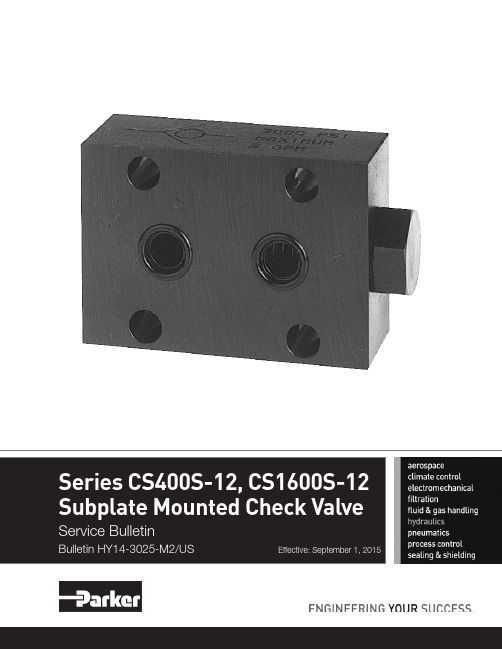
2Parker Hannifin CorporationHydraulic Valve Division Elyria, Ohio, USASubplate Mounted Check Valve Series CSBulletin HY14-3025-M2/USBul HY14-3025-M2.indd, ddpTechnical InformationSee Chart "B" for Bolt Kit No. and torque values© 2015 Parker Hannifin Corporation. All rights reserved.Bulletin HY14-3025-M2/US, 9/15Supersedes: September 15, 2003Parker Hannifin Corporation Hydraulic Valve Division520 Ternes AvenueElyria, Ohio 44035 USA T el: 440-366-5100Fax: 440-366-5253/hydraulicvalveFAILURE OR IMPROPER SELECTION OR IMPROPER USE OF THE PRODUCTS DESCRIBED HEREIN OR RELA TED ITEMS CAN CAUSE DEA TH, PERSONAL INJURY AND PROPERTY DAMAGE.• This document and other information from Parker-Hannifin Corporation, its subsidiaries and authorized distributors provide product or system options for further investigation by users having technical expertise.• The user, through its own analysis and testing, is solely responsible for making the final selection of the system and components and assuring that all performance, endurance, maintenance, safety and warning requirements of the application are met. The user must analyze all aspects of the application, follow applicable industry standards, and follow the information concerning the product in the current product catalog and in any other materials provided from Parker or its subsidiaries or authorized distributors.•T o the extent that Parker or its subsidiaries or authorized distributors provide component or system options based upon data or specifications provided by the user, the user is responsible for determining that such data and specifications are suitable and sufficient for all applications and reasonably foreseeable uses of the components or systems.WARNING – USER RESPONSIBILITYThe items described in this document are hereby offered for sale by Parker-Hannifin Corporation, its subsidiaries or its authorized distributors. This offer and its acceptance are governed by the provisions stated in the detailed “Offer of Sale” elsewhere in this document or available at /hydraulicvalve.OFFER OF SALEFor safety information, see Safety Guide SG HY14-1000 at /safety or call 1-800-CParker.SAFETY GUIDE。
SY系列水力控制阀使用手册(新)
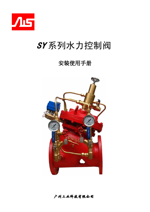
SY系列水力控制阀安装使用手册广州三业科技有限公司三业智能专家SY系列水力控制阀目 录1 概述 (2)2 恒扬程/止回阀的工作原理 (3)3 恒扬程/止回阀的应用 (6)4 恒扬程/止回阀在水泵并联中的应用 (9)5 电动泄压/安全阀的工作原理 (10)6 电动泄压/安全阀的应用 (13)7 减压/稳压阀的工作原理和应用 (14)8 阀门的安装方法 (15)9 阀门的使用和调节方法 (15)10 阀门的维护和保养 (19)11 阀门的故障分析与处理 (20)12 阀门的基本参数 (24)- 1 -V1.0广州三业科技有限公司智能铸造安全安装使用说明书1 概述SY(双控制腔、Y型阀体)系列水力控制阀为新一代的低流阻、易调节、易安装的水力控制多功能阀门,该阀门已获国家实用新型(ZL200920053994.8)和发明(ZL201010103041.5)专利授权。
阀门可在生活给水、工业给水、冶炼炉冷却循环给水、消防给水等系统上广泛应用,系列产品分别有恒扬程/止回阀、电动泄压/安全阀、减压/稳压阀等。
恒扬程/止回阀是一种自动调整给水管路特性的阀门,主要应用在柴油机水泵、电动水泵的给水管道上,以保证水泵组按设计的额定扬程及额定流量给水作业,特别是可图一以避免水泵在低扬程区的超载运行的现象,并可以防止水泵超负荷启动。
电动泄压/安全阀是一种带遥控全开启功能的调节型安全阀,可应用在给水系统恒压(安全)及系统自动巡检和带载试验的遥控泄压操作上。
减压/稳压阀是一种带遥控关闭功能的调压阀,可应用在多个给水压力分区的自动调压应用。
目前,该系列阀门已广泛应用在多种给水系统上,特别是多台水泵机组并联和多压力分区的系统上。
该系列阀门是确保系统安全以及高效运行的理想配套阀门。
恒扬程/止回阀是一种多功能、多用途阀门,可同时起到持压阀、恒压阀、动态流量调节阀、防水锤、止回阀、遥控关闭阀等多台阀门所起到的作用。
电动泄压/安全阀、减压/稳压阀同样是多功能、多用途阀门。
深圳克拉克自动化控制 水力自控阀 电动开关控制方式说明书

水力自控阀电动开关控制方式说明书深圳克拉克自动化控制有限公司 Clake Automation Co.,Ltd.一、特点二结 构 组 成、 连接导管为高压软管,具有连接方便、易维护、抗老化、耐腐蚀的特点。
软管接头材质为不锈钢,其它连接件如直接、弯头等材质均为不锈钢或黄铜。
A V-EL 水力自控电动开关阀说明书采用E S三通电动换向球阀作为控制机构,与电磁阀相比,具有耐高压、抗污能力强的特点,即使 长期不动作也不会出现结垢拒动,对水质要求较低。
E S三通换向球阀带手动功能,还具有开、闭信号接点输出的功能。
采用双道不锈钢Y形过滤器,具有在线清洗、更换过滤器的功能,在水质较差的环境下,阀体也能 正常工作。
电动开关减压阀主要部件组成及材质:四、安 装主阀三技 术 参 数、ES 三通电动换向球阀 控制方式:电动带手动、手动工作电源:220V D C/AC 阀座材质:304不锈钢压力等级:PN 25螺纹连接:R1/2″适用温度:-20℃ 200℃~环境湿度:30% 95%~防护等级:IP65位置开关 接点容量:5A/250VAC安装主阀前,请先检查阀体内是否完好,是否有杂物,如有杂物请现场清除。
主阀安装时,请注意主阀体外水流标示箭头,遵循方向安装。
管 径:DN 150工作压力:16bar 3最高流量:350m /h 3最低流量:〈1m /h 流量系数Kv:407水头损失系数K:4.8PN1.6MPa 尺寸表公 称 通径 DN(D)A B C n d 506580100125150175200225300250350400165185200220250285310340365405460520580125145160180210240270295325355410470525100120135155185210240265295320375435485448888812121212161618181818182323232326262630安装法兰尺寸表:五、接线图六、操 作 说 明1.关闭模式:当手动球阀1和手动球阀2处于如图1所示位置,E S三通电动换向球阀关闭(指示为"s h u t ")时,上游水压直接导入主阀控制腔中,阀门关闭(如图1)。
EP..R2+KBAC控制阀说明书

特性控制阀,具备带有自复位的传感器运行的流量控制, 2 通, 内螺纹和外螺纹, PN 25(EPIV)• 额定电压 AC/DC 24 V• 控制方式 调节型, 交互通信式, 混合模式• 用于闭式的冷、热水系统• 用于供热通风系统中水侧的调节控制• 通过搏力谋 MP-Bus 或常规控制进行通信• 有源传感器信号的转换和切换触点• 流体温度的测量型号概述型号DN Rp ["]G ["]V'nom [l/s]V'nom [l/min]V'nom [m³/h]kvs theor. [m³/h]PN EP015R2+KBAC 151/23/40.4225 1.5 3.225EP020R2+KBAC 203/410.6941.7 2.5 5.325EP025R2+KBAC 2511 1/40.9758.3 3.58.825EP032R2+KBAC 321 1/41 1/2 1.67100614.125EP040R2+KBAC 401 1/22 2.78166.71019.225EP050R2+KBAC5022 1/2 4.172501530.425理论kvs: 理论 kvs 值用于压降计算技术数据电气参数额定电压AC/DC 24 V 额定电压频率50/60 Hz额定电压范围AC 19.2...28.8 V / DC 21.6...28.8 V 运行功耗 4 W (DN 15, 20, 25)5 W (DN 32, 40, 50)保持功耗 3.7 W (DN 15, 20, 25)3.9 W (DN 32, 40, 50)变压器容量 6.5 VA (DN 15, 20, 25)7.5 VA (DN 32, 40, 50)连接方式电缆 1 m, 6x 0.75 mm²数据总线通信通讯协议BACnet MS/TP Modbus RTU MP-Bus节点数量BACnet / Modbus 详见接口描述MP-Bus 最多 8 个MP-Bus 兼容模式如果该设备被用于替代现有MP-Bus 系统中的EP..R-(K)MP ,该设备可以设置为MP 兼容模式。
- 1、下载文档前请自行甄别文档内容的完整性,平台不提供额外的编辑、内容补充、找答案等附加服务。
- 2、"仅部分预览"的文档,不可在线预览部分如存在完整性等问题,可反馈申请退款(可完整预览的文档不适用该条件!)。
- 3、如文档侵犯您的权益,请联系客服反馈,我们会尽快为您处理(人工客服工作时间:9:00-18:30)。
浮球控制阀说明书
一、产品简介
该产品是我公司工程技术人员参照国内外同类型的先进产品进行设计和制造的,阀体采 用了全通道流线型设计。流体阻力小、流量大,密封效果好。由于在主阀上配装了导管控制 系统,利用水力操作,可自动控制水塔或水池的液面,保养简单,灵活耐用,液位控制准确 度高,水位不受水压干扰且关闭紧密不漏水,欢迎选购。
三、工作原理
当管道从阀门的进水端给水时,由于针阀 15、球阀 14 和浮球阀 10 是常开的,所以介质 通过针阀 15 进入阀盖控制室后,又经球阀 14 和浮球阀 10 流进水箱,控制室内不能形成压 力,则进入主阀盘下面的入口压力将主阀盘托起,打开主阀向水箱内大量供水,当水箱内的 水位逐渐升高,浮起浮球后把浮球阀 10 关闭时,阀盖控制室内的水便逐渐增加压力值至把 主阀盘关闭,此时便起到了自动遥控的作用。
65
220 160 130 4-14 185 145 4-18 185 145 4-18 185 145 8-18
80
230 190 150 4-18 200 160 8-18 200 160 8-18 200 160 8-18
100 265 210 170 4-18 220 180 8-18 220 180 8-18 235 190 8-22
125 295 240 200 8-18 250 210 8-18 250 210 8-18 270 220 8-26
150 335 265 225 8-18 285 240 8-22 285 240 8-22 300 250 8-26
200 385 320 280 8-18 340 295 8-22 340 295 12-22 360 310 12-26 250 465 375 335 12-18 395 350 12-22 405 355 12-26 425 370 12-30 300 545 440 395 12-22 445 400 12-22 460 410 12-26 485 430 16-30 350 610 490 445 12-22 505 460 16-22 520 470 16-26 555 490 16-33 400 650 540 495 16-22 565 515 16-26 580 525 16-30 620 550 16-36 450 730 595 550 16-22 615 565 20-26 640 585 20-30 670 600 20-36 500 800 645 600 20-22 670 620 20-26 715 650 20-33 730 660 20-36 600 920 755 705 20-26 780 725 20-30 840 770 20-36 845 770 20-39
二、结构型式
该阀由主阀、针阀、球阀、浮球阀和微型过滤器等组成,如图下图所示。
1、阀体 8、螺栓 15、塞头
2、螺母
3、密封圈
9、阀盖 10、浮球阀
16、针型调节阀
4、阀瓣 11、螺母
5、阀杆 6、膜片压板 12、螺母 13、弹簧
7、膜片 14、球阀
公称 长 通径 度
毫米 L
0.6MPa D D1 n-d
四、安装与维护
1、主阀安装于水池或高位水塔的进水管上,最佳的安装方式是水平安装在管线上,阀盖
2
朝上,其它安装方式也可以达到操作功能。 2、安装前要彻底清除管道内的杂物,彻底冲洗管道。安装时要注意主阀体外水流标示箭
头,遵循方向安装。 3、主阀前要装一只闸阀和一个过滤器,主阀后也要装一只闸阀,以便维修。 4、试水时要先开启主阀盖上的球阀,然后慢慢开启主阀前的闸阀,此时主阀应正常向水
连接尺寸(标准值)
1.0MPa
1.6MPa
D D1 n-d D D1 n-d
2.5MPa D D1 n-d
50
200 140 110 4-14 165 125 4-18 165 125 4-18 165 125 4-18
1
公称 长 通径 度
0.6MPa
连接尺寸(标准值)
1.0MPa
1.6MPa
2.5MPa
箱内供水,关闭球阀,主阀也随之关闭。如果不能关闭,说明主阀盘下有脏物,清除脏物后 再试。主阀供水时,浮球导阀也同时流水,如果用手托起浮球,浮球导阀关闭,则主阀也随 之关闭,证明浮球导阀良好。
5、浮球阀装于主阀上,为出厂时包装方便,实际安装如图所示。 6、主阀导管进口处的微型过滤器要 2-3 个月清洗一次。
闸阀
100X 浮球控制阀 闸阀
溢流管
最高水位 水池内腔
说明: 1、此种安装方式,适用于任何口径阀门,为以后维护方便。
3