SP-SDP for Fuel Consumption and Tailpipe Emissions Minimization in an EVT Hybrid
发动机英语

发动机engine内燃机intenal combusiton engine动力机装置power unit汽油机gasoline engine汽油喷射式汽油机gasoline-injection engine火花点火式发动机spark ignition engine压燃式发动机compression ignition engine往复式内燃机reciprocating internal combustion engine 化油器式发动机carburetor engine柴油机diesel engine转子发动机rotary engine旋轮线转子发动机rotary trochoidal engine二冲程发动机two-stroke engine四冲程发动机four-stroke engine直接喷射式柴油机direct injection engine间接喷射式柴油机indirect injection engine增压式发动机supercharged engine风冷式发动机air-cooled engine油冷式发动机oil-cooled engine水冷式发动机water-cooled engine自然进气式发动机naturally aspirated engine煤气机gas engine液化石油气发动机liquified petroleum gas engine柴油煤气机diesel gas engine多种燃料发动机multifuel engine石油发动机hydrocarbon engine双燃料发动机duel fuel engine热球式发动机hot bulb engine多气缸发动机multiple cylinder engine对置活塞发动机opposed piston engine对置气缸式发动机opposed-cylinder engine十字头型发动机cross head engine直列式发动机in-line engine星型发动机radial engine筒状活塞发动机trunk-piston engine斯特林发动机stirling engine套阀式发动机knight engine气孔扫气式发动机port-scavenged engine倾斜式发动机slant engine前置式发动机front-engine后置式发动机rear-engine中置式发动机central engine左侧发动机left-hand engine右侧发动机right-hand enginePDF 文件使用"pdfFactory Pro" 试用版本创建棿physical response time of opacimeter鐢垫短冲程发动机oversquare engine长冲程发动机undersquare engine等径程发动机square engine顶置凸轮轴发动机overhead camshaft engine双顶置凸轮轴发动机dual overhead camshaft engineV形发动机V-engine顶置气门发动机valve in-head engine 侧置气门发动机side valve engine无气门发动机valveless engine多气门发动机multi-valve engine卧式发动机horizontal engine斜置式发动机inclined engine立式发动机vertical engineW形发动机w-engineI形发动机I-engineL形发动机L-engineF形发动机F-engine二冲程循环two-stroke cycle四冲程循环four-stroke cycle狄塞尔循环diesel cycle奥托循环otto cycle混合循环mixed cycle定容循环constant volume cycle工作循环working cycle等压循环constant pressure cycle理想循环ideal cycle热力循环thermodynamic cycle冲程stroke活塞行程piston stroke长行程long stroke上行程up stroke下行程down stroke进气行程intake stroke充气行程charging stroke压缩行程compression stroke爆炸行程explosion stroke膨胀行程expansion stroke动力行程power stroke排气行程exhaust stroke膨胀换气行程expansion-exchange stroke换气压缩行程exchange-compression stroke止点dead center上止点top dead center(upper dead center)下止点lower dead center(bottom dead center)PDF 文件使用"pdfFactory Pro" 试用版本创建 前置式发动机front-engine后置式发动机rear-e上止点前budc(before upper dead center)上止点后atdc(after top dead cetner)下止点前bbdc(before bottom dead center)下止点后abdc(after bottom dead center)缸径cylinder bore缸径与行程bore and stroke空气室energy chamber气缸余隙容积cylinder clearance volume燃烧室容积combustion chamber volume气缸最大容积maximum cylinder volume压缩室compression chamber排气量displacement发动机排量engine displacement活塞排量piston swept volume气缸容量cylinder capacity单室容量single-chamber capacity容积法volumetry压缩比compression ratio临界压缩比critical compression ratio膨胀比expansion ratio面容比surface to volume ratio行程缸径比stroke-bore ratio混合比mixture ratio压缩压力compression pressure制动平均有效压力brake mean effective pressure(bmep) 空燃比air fuel ratio燃空比fuel air ratio燃料当量比fuel equivalence ratio扭矩torque单缸功率power per cylinder升功率power per liter升扭矩torque per liter升质量mass per liter减额功率derating power输出马力shaft horsepower马力小时 马力时horsepower-hour总马力gross horse power总功率gross power净功率net power燃油消耗量fuel consumption比燃料消耗率specific fuel consumption空气消耗率air consumption机油消耗量oil consumption有效马力net horse powerPDF 文件使用"pdfFactory Pro" 试用版本创建ine 中置式发动机central engine左侧发动机额定马力rated horse power马力重量系数horsepower-weight factor制动功率brake horse power制动热效率brake thermal efficiency总效率overall efficiency排烟极限功率smoke limiting horsepower功率曲线power curve机械损失mechanical loss机械效率mechanical efficiency有效热效率effective thermal efficiency充气系数volumetric efficiency过量空气系数coefficient of excess air适应性系数adaptive coefficient扭矩适应性系数coefficient of torque adaptibility转速适应性系数speed adaptive coefficient强化系数coefficient of intensification校正系数correction factor换算系数conversion factor活塞平均速度mean piston speed发动机转速engine speed (rotational frequency)怠速转速idling speed经济转速economic speed起动转速starting speed最低稳定工作转速lowest continuous speed with load最大扭矩转速speed at maximum torque最高空转转速maximum no load governed speed调速speed governing超速overspeed怠速idling转速波动率speed fluctuation rate工况working condition(operating mode)额定工况declared working condition变工况variable working condition稳定工况steady working condition空载no-load全负荷full load超负荷overload部分负荷part load充量 进气 charge旋转方向direction of rotation顺时针clockwise逆时针counter-clockwise左转left-hand rotationPDF 文件使用"pdfFactory Pro" 试用版本创建w務?`噜 櫺}\蠥鼕朂0蜕 €?V ?/•稄|?祊紥9右转right-hand rotation 外径major diameter中径pitch diameter内径minor diameter径向间隙radial clearance发动机性能engine performance加载性能loading performance起动性能starting performance加速性能acceleration performance动力性能power performance排放性能emission performance空转特性no load characteristics负荷特性part throttle characteristics调速特性governor control characteristics万有特性mapping characteristics稳定调速率steady state speed governing rate 气缸体和气缸盖cylinder block and head气缸体cylinder block整体铸造cast inblock (cast enblock)发动机罩engine bonnet气缸体加强筋engine block stiffening rib气缸cylinder转子机 缸体stator缸径cylinder bore气缸体机架cylinder block frame气缸盖cylinder head配气机构箱valve mechanism casing气缸体隔片cylinder spacer气缸盖密封环cylinder head ring gasket气缸盖垫片cylinder head gasket气缸套cylinder liner(cylinder sleeve)干式缸套dry cylinder liner湿式缸套wet cylinder liner气缸水套water jacket膨胀塞expansion plug防冻塞freeze plug气缸壁cylinder wall环脊ring ridge排气口exhaust port中间隔板intermediate bottum导板guideway创成半径 转子机 generating radius缸体宽度 转子机 operating width机柱columnPDF 文件使用"pdfFactory Pro" 试用版本创建燃烧室combustion chamber主燃烧室main combustion chamber副燃烧室subsidiary combustion chamber预燃室prechamber涡流燃烧室` swirl combustion chamber分开式燃烧室divided combustion chamber涡流式燃烧室turbulence combustion chamber半球形燃烧室hemispherical combustion chamber浴盆形燃烧室bathtub section combustion chamberL形燃烧室L-combustion chamber楔形燃烧室wedge-section combustion chamber开式燃烧室open combustion chamber封闭喷射室closed spray chamber活塞顶内燃烧室piston chamber爆发室explosion chamber燃烧室容积比volume ratio of combustion cahmber燃烧室口径比surface-volume ratio of combustion chamber 通道面积比area ratio of combustion chamber passage曲轴箱通气口crankcase breather凸轮轴轴承座camshaft bearing bush seat定时齿轮室罩camshaft drive(gear)cover曲轴箱检查孔盖crankcase door曲轴箱防爆门crankcase explosion proof door主轴承盖main bearing cap气缸盖罩valve mechanism cover飞轮壳flywheel cover扫气储器scavenging air receiver活塞piston裙部开槽活塞split skirt pistonU形槽活塞U-slot piston滚花修复活塞knurled piston圆顶活塞dome head piston平顶活塞flat head piston凸顶活塞crown head piston(convex head piston)凹顶活塞concave head piston阶梯顶活塞step-head piston筒形活塞trunk piston椭圆形活塞oval piston抗热变形活塞autothermic piston不变间隙活塞constant clearance piston镶因瓦钢片活塞invar strut piston直接冷却式活塞direct-cooled piston间接冷却式活塞indirect cooled pistonPDF 文件使用"pdfFactory Pro" 试用版本创建隙radial clearance发动机性能engine perfo滑裙活塞slipper piston活塞速度piston speed活塞顶部piston head活塞裙部piston skirt整体活塞裙solid skirt活塞裙扩大衬簧piston skirt expander滑履式活塞裙slipper skirt隔热槽heat dam活塞标记piston mark活塞销piston pin活塞销孔piston pin boss活塞销衬套piston pin bushing全浮式活塞销full-floating piston pin半浮式活塞销semifloating piston pin固定螺钉式活塞销set screw piston pin活塞环piston ring组合式活塞环compound piston ring同心活塞环concentric piston ring偏心活塞环eccentric piston ring自由环free ring闭合环closed ring梯形环keystone ring半梯形环half keystone ring矩形环rectangular ring油环oil control ring开槽油环slotted oil control ring螺旋弹簧加载双坡口油环coil spring loaded slotted oil control ring 涨环expander双坡口油环double bevelled oil control ring内上坡口internal bevel top内下坡口internal bevel bottom边缘坡口油环bevelled-ege oil control ring刮油环scrapper ring钩形环napier ring镀铬活塞环chrome plated piston ring活塞衬环piston ring expander活塞环槽piston ring groove活塞环区ring zone活塞环岸piston ring land活塞环内表面back of ring曲柄连杆机构connecting rod中心曲柄连杆机构central-located connecting rod偏心曲柄连杆机构offset connecting rod铰接曲柄边杆机构hinged connecting rodPDF 文件使用"pdfFactory Pro" 试用版本创建瓦钢片活塞invar strut piston直接冷却式活塞dire连杆connecting rod连杆小头connecting rod small end连杆大头connnecting rod big end连杆杆身connecting rod shank副连杆slave connecting rod叉形连杆fork-and-blade connecting rod主连杆main connecting rod方形连杆boxed rod绞链式连杆hinged type connecting rod活节式连杆articulated connecting rod连杆盖connecting rod cap连杆轴承connecting rod bearing曲轴crankshaft整体式曲轴one-piece crankshaft组合式曲轴assembled crankshaft右侧曲轴right-hand crankshaft左侧曲轴left-hand crankshaft改变行程的曲轴stroked crankshaft曲轴前端crankshaft front end曲轴主轴颈crankshaft main journal轴颈重叠度shaft journal overlap圆角fillet主轴承main bearing曲轴止推轴承crankshaft thrust bearing薄臂轴瓦thin wall bearing shell曲轴油道crankshaft oil passage曲柄crank曲柄臂crank arm曲柄销crank pin轴套bush曲柄转角crank angle曲柄半径crank radius抛油圈oil slander角度轮degree wheel动平衡机dynamic balancer平衡重balancer weight扭振减振器torshional vibration damper扭振平衡器torsion balancer谐振平衡器harmonic balancer振动平衡器vibration balancer曲轴链轮crankshaft sprocket转子轴颈rotor journal偏心轴eccentric shaftPDF 文件使用"pdfFactory Pro" 试用版本创建od铰接曲柄边杆机构hinged connecting rodPDF曲轴箱crankcase闭式曲轴箱通风装置closed-crankcase ventilating system 飞轮flywheel飞轮齿圈flywheel ring gear飞轮芯棒cantilever飞轮芯轴flywheel spindle飞轮的惯量矩flywheel moment of inertia飞轮标记flywheel mark当量系统equivalent system当量轴长equivalent shaft length一级往复惯性力reciprocating inertia force,1st order二级往复贯性力reciprocating inertia force, 2nd order离心惯性力centrifugal inertia force配气机构valve gear凸轮轴camshaft凸轮cam整体式凸轮轴one-piece camshaft组合式凸轮轴assembled camshaft凸轮轴驱动机构camshaft drive赛车用凸轮轴race camshaft凸轮轴轴颈camshaft bearing journal凸轮轴轴承camshaft bearing凸轮轴偏心轮camshaft eccentric凸轮轴链轮camshaft sprocket凸轮轴正时齿轮camshaft timing gear凸轮轴齿轮camshaft gear wheel进口凸轮inlet cam排气凸轮exhaust cam快升凸轮quick lift cam快升缓降凸轮quick lift gradual clsing cam凸轮轮廓cam contour凸轮包角cam angle凸轮升程cam-lobe lift凸轮尖cam nose凸轮从动件cam follower齿轮传动机构gear drive正时齿轮timing gear链传动机构chain drive链轮sprocket wheel链轮盘chain sprocket正时链条timing chain带齿皮带toothed timing belt链条张紧轮chain tension gear半速齿轮half speed gearPDF 文件使用"pdfFactory Pro" 试用版本创建使用"pdfFactory Pro" 试用版本创建正时齿轮刻印记号timing gear punch mark气门valve进气过程intake process换气过程gas exchange process扫气过程scavenging process给气比delivery ratio分层充气stratified charge充量系数volumetric efficiency涡流比swirl rate进气涡流intake swirl螺旋进气道进气helical duct intake导流屏式气门进气masked valve intake切向进气道进气tangential duct intake进气紊流intake trubulence进气提前角intake advance angle进气持续角intake duration angle进气迟后角intake lag angle进面值time-area value气门升程valve lift气门正时valve timing扫气口面积scavenging port area菌形气门mashroom valve, poppet valve钠冷却气门sodium filled valve(natrium cooled valve) 双气门dual valve进气门intake valve (suction valve,inlet valve)排气门exhaust valve顶置气门overhead valve侧置气门side valve倾斜气门inclined overhead valve直立气门vertical overhead valve套筒式滑阀sleeve valve气门机构valve gear直接式气门驱动机构direct valve gear间接式气门驱动机构indirect valve gear气门杆valve stem加大气门杆oversize valve stem气门头valve head气门工作面valve face气门边限valve margin气门弹簧座valve-spring retainer气门锁片valve key气门间隙调节螺钉valve lash adjusting screw气门旋转器valve rotatorPDF 文件使用"pdfFactory Pro" 试用版本创建 顺时针clockwise逆时针counter-clockwise K气门室valve cage气门油封valve oil seal气门口valve port气门座valve seat气门座镶圈 嵌镶式气门座圈 valve seat insert(valve seat ring)气门座锥角valve seat angle气门座宽度valve seat width气门挺杆valve tappet(valve lifter)液力挺杆hydraulic tappet(lifter)无间隙挺杆zero-rush tappet (non-clearance tappet)筒形挺杆barrel type tappet油压挺杆ooil tappet滚轮挺杆roller tappet(lifter)挺杆转位tappet rotation排气门挺杆exhaust valve lifter气门导管valve guide气门杆导管stem guide气门重叠度stem overlap气门开启持续时间valve duration气门正时标记valve timing sign气门弹簧valve spring气门内弹簧inner valve spring气门外弹簧outer valve spring刚性缓冲弹簧stiff buffer spring上紧弹簧energizing spring防振气门弹簧non-surging spring弹簧座圈spring retainer蝶形弹簧belleville spring滚柱roller气门室盖valve chamber cover摇臂rocker arm高升程摇臂high lift rocker arm摇臂轴rocker arm shaft推杆push-rod摇臂支架rocker arm bracket气门摇臂室罩valve rocker chamber cover 导向轮guide wheel导杆slide bar导轨slide rail张紧轮tensioning wheel链条张紧调节装置assembly chain tension adjuster张紧带轮tensioning pulley传动带张紧装置belt tensioner同步驱动皮带synchronous beltPDF 文件使用"pdfFactory Pro" 试用版本创建PDF 文件使用"pdfFactory Pro" 试用版本创建www. 同步驱动皮轮synchronous belt pulley供油系fuel system控制燃烧系统controlled combustion system反湿气装置antipercolator电子燃油喷射electronic fuel injection蒸气回收装置vapor recovery system燃油蒸气回收系统fuel vapor recovery system液体回收装置liquid withdrawal system恒量净化管constant purge line碳罐净化管canister purge line供油量fuel delivery循环供油量fuel delivery per cycle额定供油量rated fuel delivery怠速供油量idling speed fuel delivery供油规律fuel supply rate curve油量调节装置fuel control unit供油提前角fuel supply advance angle进油计量inlet metering几何供油行程geometric fuel delivery stroke供油率fuel supply rate燃油通道fuel gallery有效行程effective stroke剩余行程remainder stroke变行程计量variable stroke metering等容卸载constant volume unloading变容卸载variable volume unloading收缩容积retraction volume燃油喷油装置fuel injection equipment燃油喷射泵fuel injection pump滚轮式燃油喷射泵roll fuel injection pump凸轮轴式燃油喷射泵camshaft fuel injection pump直列式燃油喷射泵in-line fuel injection pump伺服式燃油喷射泵servo fuel injection pump底部突缘安装燃油喷射泵base flanged mounted fuel injection pump 上部安装燃油喷射泵high flanged-mounted fuel injection pump侧向安装燃油喷射泵side-mounted fuel injection pump端部突缘安装式燃油喷射泵end flange-mounted fuel injection pump V形燃油喷射泵vee fuel injection pump脉动式燃油喷射泵jerk fuel injection pump螺纹安装燃油喷射泵screw-mounted fuel injection pump蓄能式燃油喷射泵accumulator fuel injection pump往复式燃油喷射泵reciprocating fuel injection pump驱动轴式燃油喷射泵driveshaft fuel injection pump单缸式燃油喷射泵single cylinder fuel injection pumpPDF 文件使用"pdfFactory Pro" 试用版本创建杆roller tappet(lifter)挺杆转位tappet rotation 圆柱式燃油喷射泵cylindrical fuel injection pump旋转式燃油喷射泵rotary fuel injection pump分配式燃油喷射泵distributor fuel injection pump多缸燃油喷射泵multicylinder fuel injection pump框架安装式燃油喷射泵cradle mounted injection pump喷油始点fuel injection beginning喷油终点fuel injection end喷油持续角fuel injection duration angle喷油延迟injection delay引燃喷射pilot injection启喷压力injection starting pressure峰值喷油扭矩peak injection torque峰值喷油压力peak injection pressure喷油泵油缸数目number of cylinders of an injection pump无气喷射solid injection喷射正时injection timing集中喷射group injection喷油器injector整体式喷油器unit injector喷嘴nozzle轴针式喷嘴pintle type nozzle环槽式喷嘴annular slot nozzle孔式喷嘴hole type nozzle长杆喷嘴long stem nozzle孔板式喷嘴orifice plate nozzle开式喷嘴open nozzle闭式喷嘴closed nozzle喷油提前器timing advance unit喷射泵壳体injection pump housing针阀needle芯轴central spindle喷嘴壳体nozzle body针阀升程needle lift喷嘴盖形螺母nozzle cap nut喷油器壳体nozzle holder突缘安装喷油器壳体flanged-mounted injection nozzle holder自动阻风门automatic choke阻风门拉钮choke button电控自动阻风门electric-assisted choke阻风管choke tube喉管venturi双重或三重喉管double & triple venturi阻风门拉线choke cablePDF 文件使用"pdfFactory Pro" 试用版本创建燃油喷射泵jerk fuel injection pump螺纹安装燃硬化油器小喉管booster venturi浮子系float system浮子float环形浮子annular float同心式浮子concentric float浮子支销float hinge pin浮子针阀float needle valve阀针valve needle浮子油面float level浮子臂float arm侧置浮子室式side float type怠速阀idle valve怠速针阀idle needle省油器economizer省油器阀economizer valve辅助空气阀auxiliary air-valve加速油井accelerating well加速泵accelerating pump加速泵喷嘴accelerating pump nozzle 油门throttle手油门hand throttle节气门操纵手柄throttle control lever 真空加浓器vacuum booster加浓器excess fuel device量孔体jet block怠速量孔idle metering jet主量孔main metering jet剂量阀活塞dosage valve piston空气量孔air jet燃油滤清器fuel filter沉淀杯sediment bowl串联过滤器in-line filter燃油箱内装过滤器in-tank filter调速器governor飞球式调速器flyball governor调速器governor飞球式调速器flyball governor液压调速器hydraulic governor真空转速调速器vacuum speed governor惯性调速器inertia governor离心调速器centrifugal governor调速器重锤governor weight空气滤清器及进排气系统air cleaner and intake and exhaust sytem空气滤清器air filterPDF 文件使用"pdfFactory Pro" 试用版本创建assisted choke阻风管choke tube喉管ventu冲压式空气滤清器ram air clearner恒温控制式空气滤清器thermostatic controlled air cleaner油浴式空气滤清器oil bath air cleaner纸质空气滤清器paper air clearner旋流管式空气滤清器swirl tube air filter滤清器滤芯filter element空气滤清器壳体air filter housing空气滤清器盖air filter cover滤清器密封圈filter seal ring滤网sieve滤纸盘或膜filter paper disc or membrane进气和排气系统intake and exhaust system排气管exhaust pipe排气抽气管exhaust extraction duct扫气泵scavenging pump进气预热装置intake preheater进气歧管intake manifold进气歧管真空度intake manifold vacuum冷式进气歧管cold manifold冲压式进气歧管ram intake manifold排气歧管exhaust manifold脉冲式排气歧管pulse exhaust manifold等压排气歧管constant pressrue exhaust manifold排气歧管热量控制阀exhaust manifold heat control valve 超高度歧管high-rise manifold升温横跨管道heat crossover排气横跨管道exhaust crossover预热点hot spot阻风门加热器choke heater热空气导流管hot air duct隔热板heat shield排气再循环阀exhaust -gas-recirculation消声器silencer进气消声器intake silencer排气消声器exhaust silencer金属垫片式消声器steel pack muffler玻璃丝消声器glass pack muffler空洞消声器gutted muffler前排气管front exhaust pipe尾管tail pipe消声器联接管intermediate pipe热空气管hot air pipe曲轴箱通风管crankcase bleed pipePDF 文件使用"pdfFactory Pro" 试用版本创建加团缟浔?jerk fuel injection pump螺纹安茁隔声罩acoustic hood进气消声器元件silencer element真空泵vacuum pump指示功率indicated power指示热效率indicated thermal efficiency指示油耗率indicated specific energy consumption示功图indicator diagram冷却系cooling system风冷air cooling水冷water-cooling循环流冷却系cooling recovery system自然循环液冷却系统natural circulation type cooling system热流循环液冷却系统thermo-siphon circulation type cooling system温差循环液冷却系统gravity circulation water cooling system压力式水冷却系统positive circulation cooling system加压式冷却法pressure type cooling水泵循环冷却系统pump circulation cooling system强制循环式化冷系统forced-feed water circulation system 封闭式液冷系统sealed cooling system散热器radiator片式散热器finned radiator管式散热器tubular radiator蜂窝式散热器cellular radiator哈里逊式散热器Harrison type radiator带板式散热器ribbon type radiator上水箱upper tank下水箱lower tank涨溢箱expansion tank散热器芯radiator core之字形管散热器芯film core管-片式散热器芯fin and tube core散热器加水口盖radiator filter cap压力式水箱盖radiator-pressure cap蒸气-空气泄放阀vapor-air release valve散热器护罩radiator cowl散热器百叶窗radiator shutter散热器保温帘radiator roller blind散热片cooling fin缸盖散热片cylinder head fin缸体散热片cylinder block fin控温装置temperature regulating device恒温器thermostat恒温器主阀thermostat main valve恒温器旁通阀thermostat by-pass valvePDF 文件使用"pdfFactory Pro" 试用版本创建V ? ??Y?????Y? 恒温器挠性波纹筒thermostat flexible bellows液体冷却设备liquid cooling equipment水泵water pump水泵体pump casing水泵叶轮water pump impeller旁通进水口water by-pass inlet neck循环泵circulating pump主进水口water main inlet port出水口water outlet port自调式水封self-adjusting seal unit溢流管overflow pipe导流板deflector风扇fan(blower)轴流式风扇axial flow fan离心式风扇centrifugal fan风扇壳体blower casing风扇导流罩fan cowl风扇毂fan hub风扇叶片fan blade风扇叶轮blower impeller风扇导流定子blower stator风扇皮带轮fan pulley三角皮带v-belt风扇护罩fan shroud风扇叶轮叶片impeller vane冷却用空气cooling air风扇导流叶片stator vane强制风冷forced-air cooling自然风冷natural air cooling风道air ducting润滑系lubrication system润滑lubrication气缸上部润滑upper cylinder lubrication压力润滑pressure-feed lubrication压力润滑法forced lubrication自动润滑automatic lubrication飞溅润滑splash lubrication润滑周期lubrication interval边界润滑borderline lubrication曲轴箱机油油盘crankcase oil pan油底壳oil pan机油盘放油塞sump plug集油器oil collector机油泵oil pumpPDF 文件使用"pdfFactory Pro" 试用版本创建 ?front exhaust pipe尾管tail pipe消声器联僵计量式机油泵metering oil pump齿轮式机油泵gear type oil pump转子式机油泵rotor-type oil pump机油泵出油管oil pump outlet pipe放油口oil drain hole油道oil duct断油开关cut-off cock机油散热器oil cooler机油滤清器oil filter机油粗滤器primary oil filter机油精滤器secondary oil filter全流式机油滤清器full-flow oil filter 分流式机油滤清器by-pass oil filter离心式机油滤清器centrifugal oil filter 整体式滤芯integral filtering element 细滤器滤芯filter element滤清器壳filter box滤片filtering disc机油减压器oil pressure relief valve旁通阀by-pass oil filter机油滤网oil strainer加机油孔oil filter cap滤芯轴filter shaft刮片组件cleaning edge机油量尺dipstick机油滤网oil strainer增压器supercharger增压和扫气装置pressure-charging and scavenging unit增压装置supercharging device涡轮增压器turbo-charger气波增压器comprex pressure wave supercharger增压器阻风阀supercharger blast gate增压器调节容气量的旁通阀supercharger control bypass增压器叶轮supercharger impeller惯性增压inertia supercharging机械增压mechanical supercharging涡轮增压turbo-charging增压比supercharge ratio增压压力boost pressure增压中冷inter-cooling中冷度inter-cooling level增压度supercharging level喘振surge喘振线surge linePDF 文件使用"pdfFactory Pro" 试用版本创建nk 散热器芯radiator core之字形管散热器芯^轴流式涡轮axial-flow turbine脉冲进气ram charging发动机试验engine test发动机试验规程engine test procedure发动机技术要求engine technical requirements标准大气状况standard atmospheric conditions大气压力atmospheric pressure进气温度inlet air temperature进气温度inlet air temperature功率校正power correction功率标定power rating功率换算power conversion校正系数correction factor换算系数performance test性能试验performance test起动性能试验starting ability test怠速试验idle running test道路负荷试验road load test各缸工作均匀性试验cylinder variation test背压试验back pressure test最低稳定工作转速试验lowest continuous speed test with load 背部泄漏试验back-leakage test调整试验adjustment test热平衡试验heat balance test快速磨损试验accelerated wear test热冲击试验thermo-shock test空载特性试验no-load characteristic test模拟增压试验simulated supercharging test停缸试验cylinder fuel-cut test增压机匹配试验turbo-charger matching test排气分析试验exhaust analysis test突变负荷试验sudden load change test稳定性试验stability test单缸熄火试验one cylinder shut off test例行检查试验routine inspection test验证试验verification test鉴定试验approval test可靠性试验reliability test耐久性试验durability test定型试验type approval test验收试验acceptance test现场试验field test出厂试验delivery testPDF 文件使用"pdfFactory Pro" 试用版本创建通进水口water by-pass inlet neck循环泵ci抽查试验spot check test复查试验re-check test台架试验bench test强化试验hop-up test发动机试验台engine test bed底盘测功机chassis dynamometer测功机dynamometer水力测功机hydraulic dynamometer电涡流测功机eddy current dynamometer电力测功机electric dynamometer扭矩仪torque meter转速表tachometer温度测量thermometry温度测量仪器thermometric instruments空气流量测量air flow measurement热线风速仪hot wire anemometer电子示功仪electronic indicator燃烧分析仪combustion analyzer压力传感器pressure transducer精密声级计precision sound level meter排放emission排放物emission排气污染物gaseous pollutant蒸发排放物evaporative emission曲轴箱排放物crankcase emission漏气blowby gas氨氧化物oxids of nitrogen一气化碳carbon monoxide碳氢化合物hydrocarbon甲烷methane无甲烷碳氢化合物non-methane hydrocarbons光化学活性碳氢化合物photochemically reactive hydrocarbons 微粒物particulated matter黑烟black smoke蓝烟blue smoke白烟white smoke碳烟soot光化学烟雾smog臭味odor丙烷propane排放浓度concentration of emission排气烟度exhaust smoke先期排气initial exhaust亚临界排气subcritical exhaustPDF 文件使用"pdfFactory Pro" 试用版本创建lity test 耐久性试验durability test定型?超临界排气supercritical exhaust强制排气forced exhaust自由排气free exhaust排气提前角exhaust advance angle排气迟后角exhaust lag angle排气热损失exhaust heat loss排气净化exhaust purification排气背压exhaust back pressure残余废气residual gas排气有害成分poisonous exhaust composition柴油机排烟diesel smoke综合排放浓度composite concentration of exhaust emission综合排放质量composite mass of exhaust emission排放系数emission factor排放率emission index质量排放量mass emission比排放量brake specific emission排放物控制系统emission control system排气排放物控制系统exhaust emission control system二次空气secondary air二次空气分配歧管secondary air distribution二次空气控制阀secondary air control valve二次空气转换阀secondary air switching valve二次空气转流阀secondary air diverter valve二次空气喷射装置secondary air injection system二次空气喷射管secondary air injection tube二次空气喷射减速压阀secondary air injection relief valve脉动空气装置pulsating air system二次空气泵secondary air pump曲轴箱排放物控制系统crankcase emission control system曲轴箱双通风系统crankcase closed system曲轴箱单通风系统crankcase sealed system曲轴箱强制通风装置positive crankcase ventilationPCV阀PCV valve蒸发排放物控制系统evaporative emission control system活性碳罐贮存装置charcoal canister storage system活性碳罐charcoal canister曲轴箱贮存装置crankcase storage system空气滤清器贮存装置air filter storage system燃油箱止回阀fuel tank check valve油气分离器fuel and vapor separator清除阀furge valve催化转化系统catalytic converting systemPDF 文件使用"pdfFactory Pro" 试用版本创建alve 加速油井accelerating well加速泵acceler催化燃烧分析仪catalytic combustion analyzer催化剂catalyst转化器converter催化转化器catalytic converter轴流式转化器AXIAL FLOW TYPE CONVERTER 径流式转化器RADIAL FLOW TYPE CONVERTER 下流式转化器down flow type converter上流式转化器up flow type converter双床式转化器dual bed converter单床式转化器single bed converter氧化型催化剂oxidation catalyst还原型催化剂reduction catalyst三元催化剂three-way catalyst贵金属催化剂noble metal catalyst普通金属催化剂base metal catalyst稀土催化剂rare earth catalyst催化剂耗损catalyst attrition催化剂收缩catalyst shrinkage催化剂中毒catalyst poisoning比表面积specific surface area空速space velocity载体涂料washcoat双重催化系统dual -catalyst system催化箱catalyst container载体substrate整体式载体monolithic substrate颗粒式载体pelleted substrate转化效率conversion efficiency熄灯温度light-off temperature热态反应系统thermal reacting system热反应器thermal reactor反应式歧管reactive manifold过热保护装置over heating protection system过热警报装置over heating warning system排气口衬套exhaust port liner后燃器after burner排气再循环系EGR system排气再循环exhaust gas recirculation节气门前EGR系统above throttle valve EGR system节气门后EGR 系统below throttle valve EGR system空气比例式EGR系统air proportional EGR system负荷比例式EGR系统load proportional EGR system孔口真空控制式EGR 系统ported vacuum controlled EGR system喉管真空控制式EGR系统venturi vacuum controlled EGR systemPDF 文件使用"pdfFactory Pro" 试用版本创建atalytic converting systemPDF 文件使用"pdfF排气压力控制式EGR系统exhaust pressure controlled EGR system 声速控制式EGR系统sonic controlled EGR system电子控制式EGR系统electronic controlled EGR system EGR冷却器EGR cooler EGR过滤器GER filter EGR控制阀EGR control valve EGR调压阀EGR pressure regulator再循环排气EGR gas再循环排气率EGR rate点火和喷油时刻控制系统ignition and injection timing control system 点火时刻控制系统ignition timing control system减速点火提前控制装置deceleration spark advance control推迟喷油时刻控制系统retarded injection timing control system转速控制的推迟喷油时刻retarded injection timing with speed负荷控制的推迟喷油时刻retarded injection timing with load燃油控制系统fuel control system反馈控制feedback control空燃比反馈控制系统air-fuel ratio feedback control system理论配比stoichiometric高效带window氧传感器oxygen sensor稀混合气lean mixture浓混合气rich mixture分层充气stratified charge温度补偿temperature compensating海拔补偿altitude compensating气压补偿atmospheric pressure compensating电子控制化油器electronic controlled carburetor电子燃油喷射系统electronic fuel injection system怠速限制器idle limiter阻风门开启器choke opener减速控制装置deceleration control system补气阀gulp valve。
减排前沿丨为减少石油和天然气行业的甲烷和VOCs排放,美国做了哪些行动?
减排前沿丨为减少石油和天然气行业的甲烷和VOCs排放,美国做了哪些行动?2021年11月,美国环境保护署(EPA)根据《清洁空气法》要求提出了三项独立的行动提案,针对石油和天然气井场、天然气收集和增压压缩机站、天然气加工厂及传输与储存设施的新建和现有大气排放源做出管控规定。
今天小E带大家一起了解下该提案的提出相关背景及主要内容。
EPA发布行动提案的背景早在2012年,EPA就发布了对石油和天然气行业的挥发性有机化合物(VOCs)和甲烷排放管控的新源性能标准(NSPS),这法规通常被称为“Quad O”(指的是40 CFR Part 60 Subpart OOOO)。
2016年进行修订形成了“Quad Oa”,适用于在法规生效日期后新改扩建的“受影响源”,而不适用于日期之前存在的现有排放源。
因此,该法规只管控石油和天然气作业中在用的一小部分场地和设备。
2020年,特朗普政府发布了相关政策规则,对“Quad Oa”再次做出修改,“要求取消对石油和天然气行业甲烷的监管,同时豁免石油和天然气行业的中游产业(运输和储存)的管控”。
2021年6月,国会和拜登总统利用《国会审查法》不批准该政策规则出台,故使得“Quad Oa”的原始版本立即重新生效。
但“QuadOa”仍然存在只对新改扩建的石油和天然气排放源进行监管的问题,且依据《清洁空气法》第111(d)条,若EPA公布了某一类别的排放限制,涉及像甲烷等未被列为标准空气污染物或危险空气污染物的情况,需同时发布该来源类别中现有源的性能标准。
换句话说,一旦2016年的“Quad Oa”重新生效,EPA应提出对现有石油和天然气排放源的规定。
因此,2021年11月EPA公布了NSPS Subpart OOOOc(“Q uad Oc”)中的甲烷排放指南。
各州被要求使用该示范规则来颁布州级法规,但须经EPA批准。
同时,EPA还提议在NSPS Subpart OO OOb(“Quad Ob”)下对VOCs和甲烷制定一项更严格的新源规则。
动力电池典型瞬时SOP预测方法

典型瞬时SOP预测方法瞬时SOP是指在下一时刻动力电池所能充电或者放电的最大功率能力,瞬时SOP估计方法主要包括以下四类:①混合脉冲功率特性法(HPPC)。
该方法基于动力电池上下截止电压,计算动力电池的瞬时峰值电流和功率。
由于算法简单,广泛应用于车辆能量管理领域。
②基于SOC约束的预测方法。
该方法基于许用最大和最小SOC约束实现动力电池峰值电流预测,常与其他方法组合使用。
③基于电压约束的预测法。
该方法克服了HPPC法的不足,考虑了峰值功率预测周期内动力电池OCV的变化,预测结果更为可靠。
④多约束动态法(Multi-Constrained Dynamic Method,MCD)。
该方法综合多个约束变量,如端电压、电流、SOC等,实时预测动力电池系统SOP;同时综合考虑电化学动力学、热力学、迟滞效应等动态响应特性对SOP预测结果的影响。
上述四种SOP预测方法的实施细节如下:1.HPPC法HPPC法是在美国“新一代汽车联合体”合作框架下由爱达荷国家工程与环境实验室提出的计算方法。
该方法使用Rint模型估计动力电池单体的SOP。
动力电池系统中每个单体的端电压可以表示为式中,下角m指的是第m个动力电池单体;U O C,m [z m(t)]是单体m在SOC为z m(t)处的OCV值;i L,m(t)为单体m的负载电流;R i为每一个单体在充电或放电时的内阻,其值的大小需根据电流方向而定。
考虑到动力电池端电压受限于上下截止电压的约束,单体m的充放电峰值电流可以计算为式中,U t,m a x和U t,m i n分别为动力电池的充电截止电压和放电截止电压;和分别为单体m的峰值充电电流和峰值放电电流。
假设动力电池组由n个单体组成,其中有n s个模组串联,每个模组由n p 个单体并联组成,则动力电池组峰值功率可表示为HPPC法可预测动力电池系统的瞬时SOP,但是不能预测L×Δt时间间隔的持续功率;另外所使用的Rint模型未能精确描述动力电池的动态电压特性,导致预测的SOP 过大而引起过充电和过放电问题,进而威胁到动力电池的使用安全。
卡梅伦液压数据手册(第 20 版)说明书
iv
⌂
CONTENTS OF SECTION 1
☰ Hydraulics
⌂ Cameron Hydraulic Data ☰
Introduction. . . . . . . . . . . . . ................................................................ 1-3 Liquids. . . . . . . . . . . . . . . . . . . ...................................... .......................... 1-3
4
Viscosity etc.
Steam data....................................................................................................................................................................................... 6
1 Liquid Flow.............................................................................. 1-4
Viscosity. . . . . . . . . . . . . . . . . ...................................... .......................... 1-5 Pumping. . . . . . . . . . . . . . . . . ...................................... .......................... 1-6 Volume-System Head Calculations-Suction Head. ........................... 1-6, 1-7 Suction Lift-Total Discharge Head-Velocity Head............................. 1-7, 1-8 Total Sys. Head-Pump Head-Pressure-Spec. Gravity. ...................... 1-9, 1-10 Net Positive Suction Head. .......................................................... 1-11 NPSH-Suction Head-Life; Examples:....................... ............... 1-11 to 1-16 NPSH-Hydrocarbon Corrections.................................................... 1-16 NPSH-Reciprocating Pumps. ....................................................... 1-17 Acceleration Head-Reciprocating Pumps. ........................................ 1-18 Entrance Losses-Specific Speed. .................................................. 1-19 Specific Speed-Impeller. .................................... ........................ 1-19 Specific Speed-Suction...................................... ................. 1-20, 1-21 Submergence.. . . . . . . . . ....................................... ................. 1-21, 1-22 Intake Design-Vertical Wet Pit Pumps....................................... 1-22, 1-27 Work Performed in Pumping. ............................... ........................ 1-27 Temperature Rise. . . . . . . ...................................... ........................ 1-28 Characteristic Curves. . ...................................... ........................ 1-29 Affinity Laws-Stepping Curves. ..................................................... 1-30 System Curves.. . . . . . . . ....................................... ........................ 1-31 Parallel and Series Operation. .............................. ................. 1-32, 1-33 Water Hammer. . . . . . . . . . ...................................... ........................ 1-34 Reciprocating Pumps-Performance. ............................................... 1-35 Recip. Pumps-Pulsation Analysis & System Piping...................... 1-36 to 1-45 Pump Drivers-Speed Torque Curves. ....................................... 1-45, 1-46 Engine Drivers-Impeller Profiles. ................................................... 1-47 Hydraulic Institute Charts.................................... ............... 1-48 to 1-52 Bibliography.. . . . . . . . . . . . ...................................... ........................ 1-53
常压储罐事故分析及建议
RISK Engineering Position Paper
Atmospheric Storage Tanks
February 2011
Contents
Section 1. 2. 3. 4. 5. 5.1 6. 6.1 7. 7.1 7.2 8. 9. 10. 10.1 10.2 11. 11.1 11.2 11.3 12. 13. 14. Title..............................................................................................................................Page Background...................................................................................................................................... 3 Objective.......................................................................................................................................... 3 Scope. .............................................................................................................................................. 3 Selection of Atmospheric Storage Tanks............................................................................................ 4 Layout and Spacing........................................................................................................................... 5 Bunds (Dykes)................................................................................................................................... 6 Primary Containment........................................................................................................................ 7 Tank Design & Operation. ................................................................................................................. 7 Secondary Containment................................................................................................................. 10 Bund Integrity (leak tightness)........................................................................................................ 10 Tertiary Containment...................................................................................................................... 11 Overfill Protection........................................................................................................................... 12 Maintenance and Inspection........................................................................................................... 13 Leakage and Fire Detection............................................................................................................. 14 Leak Detection................................................................................................................................ 14 Fire Prevention and Protection........................................................................................................ 14 Fire Fighting Systems...................................................................................................................... 16 Water Systems................................................................................................................................ 16 Foam Fire Fighting Systems............................................................................................................ 16 Application Rates............................................................................................................................ 18 References to Industry Losses......................................................................................................... 19 References to Industry Standards.................................................................................................... 19 Appendices..................................................................................................................................... 20 Appendix A - Assessment Checklist................................................................................................. 20 Appendix B - Mechanical Component Checklist for Floating Roof Tank Inspections......................... 21 Appendix C - Loss Incidents. ........................................................................................................... 22
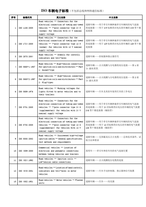
ISO车辆电子标准(不包括总线和网络通信标准)中英文对照
17
ISO 4141-3:2006
道路车辆——多芯联结电缆——第 3 部分:非屏蔽铠装低 压电缆的尺寸,结构和标记
18
ISO 4141-4:2001
道路车辆——Leabharlann 芯连接电缆——第 4 部分:螺旋型电缆总 成实验方法和性能要求
19
ISO 4148:2004
道路车辆——特殊警告灯——尺寸
20
ISO 4165:2001
5
ISO 3553-2:1997
道路车辆——点火线圈与分电器的高压连接——第 2 部 分:插头类型
6
ISO 3559:1976
道路车辆——汽车及其挂车装用灯具的工作电压
7
ISO 3731:2003
道路车辆——用于牵引车辆和被牵引车辆间的电气连接 的连接器——用于 24 伏标称供应电压的车辆的电气装置 24S 型 7 极连接器(辅助型)
ISO 车辆电子标准(不包括总线和网络通信标准)
序号 标准代号 英文名称 Road vehicles -- Connectors for the electrical connection of towing and towed vehicles -- 7-pole connector type 24 N (normal) for vehicles with 24 V nominal supply voltage Road vehicles -- Connectors for the electrical connection of towing and towed vehicles -- 7-pole connector type 12 N (normal) for vehicles with 12 V nominal supply voltage Road vehicles -- Symbols for controls, indicators and tell-tales Road vehicles -- High-tension connections for ignition coils and distributors -- Part 1: Socket-type Road vehicles -- High-tension connectors for ignition coils and distributors -- Part 2: Plug-types Road vehicles -- Working voltages for lights fitted to motor vehicles and to their trailers Road vehicles -- Connectors for the electrical connection of towing and towed vehicles -- 7-pole connector type 24 S (supplementary) for vehicles with 24 V nominal supply voltage Road vehicles -- Connectors for the electrical connection of towing and towed vehicles -- 7-pole connector type 12 S (supplementary) for vehicles with 12 V nominal supply voltage Road vehicles -- Unscreened high-voltage ignition cables -- General specifications, test methods and requirements Commercial vehicles -- Location of electrical and pneumatic connections between towing vehicles and trailers Road vehicles -- Ignition coils -Low-tension cable connections Road vehicles -- Location of hand controls, indicators and tell-tales in motor vehicles Road vehicles -- Motor vehicles -- Flasher units 中文名称 道路车辆——用于牵引车辆和被牵引车辆间的电气连接 的连接器——用于 24V 标称供应电压的车辆的 24N 型 7 极 连接器
关于某轻型商用车搭载1.5l自然吸气发动机降低颗粒物(pn、pm)排放的控制方法
Control method of reducing particulate matter (PN, PM) Emission on a light commercial vehicle with 1. 5 L naturally aspirated engine
PENG li, HUANG De-gao, DU Song (Chongqi Sokon Power CO. LTD, Chongqing, 400033, China) Abstract: The control of PM in PFI engine emission pollutants is proposed for the first time in the national 6 regulations, and its limit value is consistent with that of GDI engine. At present, domestic light commercial vehicles mainly carry PFI gasoline engine, and the emission control of PM is the first time in the world・ In this paper, the influencing factors of PM pollutant emission from PFI gasoline engine carried by light commercial vehicles are put forward, and the control methods are found out to effectively reduce the emission of PM pollutants in WLTC. Key Words: light commercial vehicles; pollutant control; PM
IPCC国家温室气体清单指南2-5源于燃料和溶剂使用的非能源产品
第5章源于燃料和溶剂使用的非能源产品作者Jos G. J. Olivier (荷兰)Domenico Gaudioso (意大利)、Michael Gillenwater (美国)、Chia Ha (加拿大)、Leif Hockstad (美国)、Thomas Martinsen (挪威)、Maarten Neelis (荷兰)、Hi-chun Park (韩国)和Timothy Simmons (英国)参加作者Martin Patel(荷兰)目录5源于燃料和溶剂使用的非能源产品..........................................................................................................5.5 5.1导言......................................................................................................................................................5.5 5.2润滑剂使用..........................................................................................................................................5.65.2.1导言..............................................................................................................................................5.65.2.2方法学问题..................................................................................................................................5.65.2.2.1方法选择............................................................................................................................5.75.2.2.2排放因子的选择................................................................................................................5.95.2.2.3活动数据选择....................................................................................................................5.95.2.2.4完整性................................................................................................................................5.95.2.2.5建立一致的时间序列........................................................................................................5.95.2.3不确定性评估..............................................................................................................................5.95.2.3.1排放因子不确定性..........................................................................................................5.105.2.3.2活动数据不确定性..........................................................................................................5.105.2.4质量保证和质量控制(QA/QC)、报告和归档....................................................................5.105.2.4.1质量保证和质量控制......................................................................................................5.105.2.4.2报告和归档......................................................................................................................5.10 5.3固体石蜡使用....................................................................................................................................5.105.3.1导言............................................................................................................................................5.105.3.2方法学问题................................................................................................................................5.105.3.2.1方法选择..........................................................................................................................5.115.3.2.2排放因子的选择..............................................................................................................5.125.3.2.3活动数据选择..................................................................................................................5.125.3.2.4完整性..............................................................................................................................5.135.3.2.5建立一致的时间序列......................................................................................................5.135.3.3不确定性评估............................................................................................................................5.135.3.3.1排放因子不确定性..........................................................................................................5.135.3.3.2活动数据不确定性..........................................................................................................5.135.3.4质量保证和质量控制(QA/QC)、报告和归档....................................................................5.135.3.4.1质量保证和质量控制......................................................................................................5.135.3.4.2报告和归档......................................................................................................................5.13 5.4沥青生产和使用................................................................................................................................5.145.4.1导言............................................................................................................................................5.145.4.2方法学问题................................................................................................................................5.155.4.3完整性........................................................................................................................................5.155.4.4不确定性评估............................................................................................................................5.16 5.4.5报告和归档................................................................................................................................5.16 5.5溶剂使用............................................................................................................................................5.16 5.5.1导言............................................................................................................................................5.16 5.5.2完整性........................................................................................................................................5.17 5.5.3建立一致的时间序列................................................................................................................5.17 5.5.4不确定性评估............................................................................................................................5.17公式公式5.1 计算源自非能源产品使用的CO2排放的基本公式...............................................................5.5公式5.2 润滑剂 – 方法1........................................................................................................................5.7公式5.3 润滑剂 – 方法2........................................................................................................................5.8公式5.4 石蜡 – 方法1..........................................................................................................................5.11公式5.5 石蜡 – 方法2..........................................................................................................................5.11图图5.1源自润滑剂和石蜡的排放的部门分配........................................................................................5.7图5.2源于润滑剂非能源使用的CO2决策树.......................................................................................5.8图5.3 源自固体石蜡非能源使用的CO2决策树................................................................................5.12表表5.1 燃料和其它化学产品的非能源产品使用........................................................................................5.6表5.2 所有润滑油、油脂和润滑剂的缺省氧化比例...............................................................................5.9框框5.1 沥青生产和使用.............................................................................................................................5.145 源于燃料和溶剂使用的非能源产品 5.1导言本节提供了估算源自化石燃料排放的方法,化石燃料首次作为初级使用产品使用,而非:1)作为能源使用的燃料和2)用作原料或还原剂。
国际海事组织发布PSC检查燃油取样新准则
国际海事组织发布PSC检查燃油取样新准则国际海事组织(IMO)海洋环境保护委员会(MEPC 75)第75届会议于2020年11月通过了《防污公约》附件VI的修正案,引入了一种从船舶燃油罐中抽取燃油样品以验证硫含量的方法。
新的修正案将于2022年4月1日生效。
根据所介绍的方法,船东和船上的高级船员应做好准备应对港口国监督检查官可能提出的从船舶燃油舱取样的要求,而不仅仅是从服务油箱和燃油箱之间的燃油管线取样的要求。
此外,国际海事组织还发布了拟在船上使用或携带的燃油的船上取样新准则。
BIMCO会员可以在下面链接里阅读更多有关法定燃料取样的信息,并下载新的船上取样指南(/ships-ports-and-voyage-planning/environment-protection/emission-to-air/how-port-state-control-will-sample-fuel-oil-going-forward)。
在这种情况下,至关重要的是,各国必须加强和实施并执行在其管辖范围内运营的燃油供应商的燃油许可计划。
既要确保供给船只上的燃油实际上符合法定的限硫标准,同时也要确保燃油满足防污公约附件六中第18条的规定最高级质量目标:例如确保燃油符合ISO标准中ISO 8217:2017的参数燃料油不应包括危害船舶安全或对机械性能产生不利影响或对人员有害或总体上造成额外空气污染的任何添加物质或化学废物。
波罗的海国际海运理事会、国际航运公会、国际独立油船船东协会和世界航运理事会向mepc75提交了一份提案,鼓励所有国家对在其管辖范围内运营的燃油供应商实施并执行强制性许可计划。
该提案目前正在国际海事组织内部进行讨论,有望成为国际海事组织现有的《成员国/沿海国最佳做法指南》(MEPC.1/第884号通告)的附件。
能源移动源燃烧
3.2.5
报告表和工作表 .................................................................................................................3.31
3.3
非道路运输 .........................................................................................................................3.31
3.4.1.1
方法的选择 .........................................................................................................................3.38
3.4.1.2
排放因子的选择 .................................................................................................................3.41
第3章 移动源燃烧
第 3 章:移动源燃烧
《2006 年 IPCC 国家温室气体清单指南》
3.1
第 2 卷:能源
作者
概述 Christina Davies Waldron (美国) Jochen Harnisch (德国)、Oswaldo Lucon (巴西)、R. Scott Mckibbon (加拿大)、Sharon B. Saile (美国)、Fabian Wagner (德国)、和 Michael P. Walsh (美国)
- 1、下载文档前请自行甄别文档内容的完整性,平台不提供额外的编辑、内容补充、找答案等附加服务。
- 2、"仅部分预览"的文档,不可在线预览部分如存在完整性等问题,可反馈申请退款(可完整预览的文档不适用该条件!)。
- 3、如文档侵犯您的权益,请联系客服反馈,我们会尽快为您处理(人工客服工作时间:9:00-18:30)。
Abstract—Control strategies have been developed for Hybrid Electric Vehicles (HEV) that minimize fuel consumption while satisfying a charge sustaining constraint. Since one of the components of an HEV is typically the ubiquitous internal combustion engine, tailpipe emissions must also be considered. This paper uses Shortest-Path Stochastic Dynamic Programming (SP-SDP) to address the minimization of a weighted sum of fuelconsumption and tailpipe emissions for an HEV equipped with adual mode Electrically Variable Transmission (EVT) and a catalytic converter. The shortest path formulation of SDP is chosen to directly address the charge sustaining requirement. Using simple methods, an SP-SDP solution required more than eight thousand hours. Using linear programming and duality, an SP-SDP problem is solved in about three hours on a desktop PC. The resulting time-invariant feedback controller reduces tailpipe emissions by more than 50% when compared to a popular baseline controller.Index Terms —Hybrid electric vehicle, dynamicprogramming, fuel economy, powertrain controlI. INTRODUCTIONThe problem of maximizing fuel economy for charge sustaining hybrid electric vehicles (HEVs) has been extensively studied. Many early control policies were based on heuristics [1-5]. In some systems, the heuristics were formalized using fuzzy logic [6]. More recent control laws have used some form of optimization to determine the power split between the engine and the electric motors. These optimization techniques explicitly minimize the fuel consumption subject to a charge sustaining constraint. Deterministic dynamic programming is one optimization technique. It has been used to develop optimal trajectories [7-10] . These trajectories have been used to gain insight and develop heuristic control laws [8]. Recently, the concept of directly designing an HEV control law through infiniteManuscript received XXX XX, 2006.Ed D. Tate is with General Motors, Hybrid Powertrain Engineering, Troy, Michigan 48007 USA (phone: 248-310-4488; fax: 248-680-5119; e-mail: ed.d.tate@ , etate@ ) . I think you should say you are withUofM also.J. W. Grizzle is with the Department of Electrical Engineering and Computer Science, University of Michigan, Ann Arbor, Michigan 48109-2122, USA, (e-mail: grizzle@). Huei Peng is with the Mechanical Engineering Department, University ofMichigan, Ann Arbor, Michigan 48109-2133, USA, (e-mail: hpeng@). horizon, discounted cost, stochastic dynamic programming(SDP) was developed [11, 12]. As noted in [13], the discounted cost criteria is chosen for expediency and is difficult to justify on engineering grounds. Therefore, in this work, a variation on infinite horizon SDP, known as Shortest Path SDP [14] is used to create a charge sustaining HEV energy management policy. In addition to fuel economy, HEVs must also be certified tosome tailpipe emissions level by the EPA or CARB [15-18]. There are multiple categories of emissions. A manufacturer chooses the certification level of a vehicle model to achieve specific goals for their production fleet. This choice usually involves a tradeoff among fleet objectives, vehicle cost objectives, technical feasibility, and fuel economy objectives. During development, the initial goal of a particular certification level may change as tradeoffs become more apparent.Prior work has focused on minimization of fuelconsumption and engine out emissions. If catalysts or otherafter treatments are used, minimization of engine out emissions does not guarantee minimization of tailpipeemissions. Therefore, there is a need for techniques to design controllers that minimize both fuel economy and tailpipeemissions.This paper shows how shortest path stochastic dynamicprogramming (SP-SDP) is used to design controllers that minimize fuel consumption and tailpipe emissions. This application of SP-SDP is illustrated on a dual mode EVT HEV [19] with a thermally transient catalyst. A collection of controllers is created and evaluated. Each controller minimizes a unique weighted combination of fuel consumption and emissions. Together, these controllers are used to estimate the Pareto set [20] . From the Pareto set, the tradeoffs between fuel consumption and tailpipe emissions are determined. To generate the control laws, an objective to minimize a weighted combination of fuel consumption and tailpipe emissions, a vehicle model, a powertrain model, and astochastic driver model are combined to form a SP-SDP. This SP-SDP is solved using a collection of techniques which include Linear Programming [21-29], barycentric interpolation [30], and constraint generation [26]. A novel interpretation of LP duality [31] is used to solve the Linear Program (LP). The technique of state censoring is introduced. This technique ignores areas in the state space which areknown to be rarely, if ever visited. Finally, the calls to the model during construction of the SP-SDP are reduced bytaking advantage of linearity in the model. Combined, these SP-SDP for Fuel Consumption and Tailpipe Emissions Minimization in an EVT HybridEd D. Tate, J. W. Grizzle, and Huei Pengtechniques allow solution of the SP-SDP in less than three hours on a 3.0 GHz, single core Pentium CPU. II. P LANT M ODELThe controller development uses a plant model that includes the powertrain, the vehicle, and the driver. Figure 1 illustrates the major components in the model and their interactions. These components include the engine, the Dual-Mode Electrically Variable Transmission (DM-EVT), two electric machines, the final drive ratio, the battery pack, the chassis, the body, the tires, and the chassis brakes. The powertrain and the vehicle models are deterministic. The driver model is stochastic.The transmission is based on the design in [19] and illustrated in Figure 2. It has four shafts which are coupled to the engine, the wheels through the final drive ratio, and the two electric machines. The electric machines are identified as ‘A’ and ‘B’. Unlike a fixed-gear transmission, the engine speed is independent of the vehicle speed. However, the electric machines speeds are determined by the transmission mode, the speed of the engine, and the speed of the vehicle. The engine and vehicle speeds are independent because the engine acceleration and vehicle acceleration can be separately controlled using the torques from the engine and electric machines. The range of acceleration is limited by the engine and motor torque limits which vary depending on individual component speeds. Proper selection of the modes in the transmission avoids these acceleration limits by changing the ratio of motor speeds to engine and vehicle speeds. This allows the motors to operate in regions with less torque restriction.In the DM-EVT transmission, two no-slip or dog clutches are used. To change modes, the clutches are released allowing motor speeds to be controlled independently of the engine and vehicle speeds. The engine torque and machine torques are used to accelerate the electric machines to a speed where one of the clutches can close without slipping. For modeling, this event is assumed to occur instantaneously with negligible fuel and battery energy usage. The kinematics of the transmission and the vehicle are illustrated in Figure 3.The driver is modeled as a stochastic process that generates the input now a , which represents the driver’s acceleration request, in Figure 1. The driver model specifies the distribution of the next acceleration commands, the dynamics for updating now a , and the probability that the vehicle will continue to operate with the key on. When the controller is evaluated, the state now a is replaced by the acceleration command from the vehicle’s driver.Although the plant is naturally described in continuous time, to facilitate the application of SP-SDP, a discrete time model with a one second time step is used. This is the same rate used for similar work in [11, 12].A. The Plant Model SummaryThe plant model has states associated with the engine speed, e ω, the vehicle speed, veh v , the battery state of charge, batt q , the catalyst temperature, cat T , and the driver accelerationcommand, now a . The model states are combined to form the state vector:[]5Tvehbatte catnow x v q T a ω∈⊂X . (1)The transmission mode is allowed to change at any time and the changes are assumed to occur instantaneously, therefore, there is no state associated with transmission clutch configuration. The transmission mode input is{}trn 'mode 1','mode 2'trn M ∈=M . (2) When trn M is equal to ‘mode 1’ it means that clutch 1 inFigure 2 is closed with clutch 2 open. Likewise, if trn M is equal to ‘mode 2’, then clutch 2 is closed with clutch 1 open. When the engine changes mode between ‘on’ and ‘off’, the transition from a running speed to motionless and from motionless to an idle speed occurs instantaneously in the model. The input to change the engine mode is{}e 'eng on','eng off'e M ∈=M . (3) When e M is equal to ‘eng off’, the engine is motionless withits brake torque equal to zero. Otherwise, the engine is restricted to operate between a minimum idle speed and a maximum redline speed, with the torque limited by the engine’s capabilities.The engine torque, e T , electric machine A torque, A T , electric machine B torque, B T , and chassis brake torque, k T , are all independently controlled. These torque inputs are combined with the transmission mode command, trn M , and the engine mode command, e M , to form the input vector for the plant:[]24plant plant trn e e A B k u M M T T T T ∈⊂×U . (4) The discrete-time dynamics of the model are()()()()()(),,1,,,,,,,,,,,,,,,,veh batt e cat now v k plant k k q k plant k k k plant k plant k k k plant k k T k plant k k a k plant k k f x u w f x u w x f x u w f x u w f x u w f x u w ω+⎡⎤⎢⎥⎢⎥⎢⎥⎢⎥==⎢⎥⎢⎥⎢⎥⎢⎥⎣⎦. (5)In these equations,,k next k w a = (6) where ,next k a is the output of the driver model. The variable next a represents the vehicle acceleration command in the next time step, which is different than now a which represents the current vehicle acceleration command.The outputs of the plant model are f W , the fuel consumedper time step, e W , the normalized tailpipe emissions per time step, and batt P , the battery power. The output functions are()()()(),,,,,,,,,,,,,,,f e batt W k plant k k f k e k plant k plant k k W k plant k k batt k P k plant k k h x u w W W h x u w h x u w P h x u w ⎡⎤⎡⎤⎢⎥⎢⎥⎢⎥==⎢⎥⎢⎥⎢⎥⎢⎥⎣⎦⎣⎦. (7)In (7), the variable w represents the stochastic input to the system and is used for the sake of generality. These functions do not use w in determining the output values. However, while the models used in this work assume the engine behaves deterministically, unmodeled dynamics in the engine can cause the fuel consumption and engine-out emissions toappear to have a stochastic component. For example, manifold dynamics, exhaust gas recirculation (EGR) valve position,EGR valve control, and engine temperatures are not modeled. These dynamic behaviors will cause fuel consumption and engine out emissions to have a distribution of values. Therefore, this notation is maintained because of generalityand applicability.The constraints on operation of the individual componentsare grouped into a vector function such that feasibility isequivalent to all elements in the vector being less than or equal to zero. This constraint vector is()()()()()(),,,,,,vehicle plant engine plant plant plant catalyst plant motors plant battery plant g x u g x u g x u g x u g x u g x u ⎡⎤⎢⎥⎢⎥⎢⎥⎢⎥=⎢⎥⎢⎥⎢⎥⎢⎥⎣⎦. (8) These constraints ensure that components operate withintheir limits and the system does not leave a safe operatingenvelope in the state space. For example, an action choice is not feasible if it results in the engine operating beyond the maximum engine speed. Equation (8) is used to define the set of feasible actions ()(){}plant plant ,0,plant plant plant x u g x u x =∈≤∈U U X . (9)The model and constraint equations are constructed so that a feasible action always exists by insuring that ()plant x U is non-empty for all x ∈X .The detailed model parameters and equations are in [32].B. Driver Behavior Model The driver model is part of the plant model. The driver model predicts the distribution of future accelerations and the probability the vehicle will be turned off at the next time step. In [12], torque is used in the stochastic driver model. The use of torque or power tightly couples the driver model to the characteristics of a vehicle. In other words, if the driverfollows a velocity trace in a small economy vehicle andfollows the same trace in a large truck, then different torque based driving models result. The torque and power required at the wheels varies with vehicle, while the acceleration is identical for the same driving cycle. Therefore, using acceleration, the driver model is constructed and maintained independent of vehicle characteristics.The driver model consists of two conditional probabilities. One conditional probability is()~Pr ,next next veh now a a v a , (10) where next a is the vehicle acceleration at the next time step,veh v is the velocity at the current time step, and now a is theacceleration at the current time step. This conditional probability specifies the distribution of acceleration commands at the next time step. The other conditional probability defines the probability that the vehicle will continue to operate at the next time step. This model is()()Pr ,Pr next time step vehicle is '',on veh now veh now v a on v a =. (11) Both conditional probability models are constructed using discrete values of veh v and now a selected to match the sample points used in the SP-SDP. The values of next a are limited to a finite set of discrete values,{}12,,,next n a w a a a =∈W = . (12)For generality, the variable w represents the stochastic variable in the model. The values in (12) correspond to thediscrete values of now a used to construct the SP-SDP. III. P ROBLEM D EFINITION Consider the problem of determining the optimal tradeoffsbetween expected fuel consumption and expected tailpipeemissions. One way to do this is to find a collection of controllers, where each controller minimizes a specific combination of fuel consumption and emissions, while satisfying plant and system constraints.A. Control Constraints In addition to the plant constraints in (8), the system imposes constraints on the action choices. The system constraints include the charge sustaining constraint previously discussed. In addition, the controller must choose actions thatminimize the error in matching the driver’s acceleration command and minimize chassis (friction) brake torque. Thechassis brake torque is constrained to minimize energy loss and to minimize brake wear. These three constraints are thesystem constraints and further restrict the set of feasible actions.Since a charge sustaining constraint is difficult to directlyaddress, it is reformulated as an objective to minimize the deviation from an SOC set point at each time step. The relationship between this objective, fuel economy optimality, and satisfaction of the charge sustaining constraint is discussed in Appendix A. This objective cost is defined as()()()20,,,,batt q plant q q plant c x u w K f x u w q =⋅−. (13) The values of q K and 0q are selected by experimentation to achieve charge sustaining operation over a range of driving conditions. The remaining constraints on acceleration and chassis braking are satisfied by restricting the set of feasible actions. Let (),sys plantg x u be defined so that the constraints onacceleration and braking are satisfied with no accelerationerror and no chassis braking torque if (),0sys plant g x u ≤. (14)Since the set of action choices in (9) that satisfy (14) may be empty, a relaxation is introduced using the vector sys ε. Therelaxed form of (14) becomes (),0sys plant sys g x u ε−≤. (15) If the acceleration error is zero and no brake torque is used then equation (15) is satisfied with all elements in sys ε equal to zero. The relaxed system constraints, (15), and the plant constraints, (8), define the set of feasible actions at each state. Let()()()(){}*,0sys plant plant plant sys plant sysx u x g x u x ε+=∈−≤U U (16)be the set of feasible control choices available for control. At many values of x , this set will be non-empty with everyelement in ()*sys x ε equal to zero. Otherwise, ()*sys x ε is a vector with one or more elements containing the smallest non-zero value that ensures ()sys plant x +U is non-empty. There are many ways the value of ()*sys x ε can be found. For this work, the element in ()*sys x ε that relaxes the chassis braking torque constraint is increased until a feasible action is available or the constraint is no longer active. If relaxing the chassis braking torque constraint does not yield a feasible action, then the element in ()*sys x ε corresponding to the acceleration error is increased until a feasible action is found. By construction of the model, relaxation of acceleration error is guaranteed to find at least one feasible action.B. Control ObjectivesThe objective for the controller is to minimize a weighted combination of total expected fuel consumption and total expected tailpipe emissions subject to the system and plant constraints. The set in (16) defines the actions available to thecontroller for use in minimizing the objective.The total expected fuel consumption while operating under the feedback law ()x π is()()0,0,,W f f k plant k k k J x E c x u w π∞=⎛⎞=⎜⎟⎝⎠∑. (17) The total expected tailpipe emissions under the same control law is ()()0,0,,W e e k plant k k k J x E c x u w π∞=⎛⎞=⎜⎟⎝⎠∑. (18)In these equations, ()f c ⋅ is the fuel consumption per timestep and ()e c ⋅ is the normalized tailpipe emissions per timestep. In calculating these total costs, the evolution of the stateis(),,,k plant k plant k k x f x u w =. (19)The stochastic input, k w , is generated by the probability distribution in (6) and (),plant k k u x π=, (20)where ()π⋅ is a static, time-invariant, state feedbackcontroller. To satisfy the charge sustaining constraint, a cost for SOC variation,()()0,0,,Wq q k plant k k k J x E c x u w π∞=⎛⎞=⎜⎟⎝⎠∑, (21) is introduced as a minimization objective. This objective uses ()q c ⋅ in (13). The optimization problem is to find a controller,*π, that satisfies 0x ∀∈X()()()()(){}*0000arg inf 1f e q x J x J x J x πππππαα∞∈∏∈⋅+−⋅+, (22)where ∞Π is the set of all possible time-invariant state feedback controllers with (),plant k sys plant k u U x +∈ for all k and[]0,1α∈. Without special structure, the optimization problem in (22) is intractable. Fortunately, this optimization problem can be significantly simplified. Under the assumption that perfect, or noise free, state information is available, a controller that minimizes (22) is found using dynamicprogramming. A controller that minimizes (22) satisfies the dynamic programming equations [33-35],()()()()()*,,arg min ,,plant sys plant plant plant W u x plant plant c x u w x E V f x u w π+∈⎧⎫⎛⎞⎪⎪⎜⎟=⎨⎬⎜⎟+⎪⎪⎝⎠⎩⎭U , (23)and uses the value function defined as()()()()(),,min ,,plant sys plant plant plant W u x plant plant c x u w V x E V f x u w +∈⎧⎫⎛⎞⎪⎪⎜⎟=⎨⎬⎜⎟+⎪⎪⎝⎠⎩⎭U . (24) In these equations, ()plant c ⋅ is the cost for operation at eachtime step, defined here as()()()()()(),,,,1,,,,plant plant f plant e plant q plant c x u w c x u w c x u w c x u w αα=⋅+−⋅+, (25) and formed from the cost functions in (17), (18), and (21).The parameter α is used to select the relative weighting of emissions versus fuel consumption. IV. C ONTROLLER S YNTHESIS VIA A PPROXIMATE SP-SDPWhile an SP-SDP controller could be designed that worked on the full state and action space defined in (1) and (9), theSP-SDP controller design problem is greatly simplified by first creating a low-level controller. In this case, the low-level controller is a static mapping from a set of synthetic high-level inputs, U to the plant inputs, plant U .A. Simplified Action Set via a Low-Level Controller To generate the high-level controller, the state and action spaces are spatially discretized; this is referred to as sampling. The sample points are used to generate the value function in(24). It is desirable to have a minimal number of samples since this minimizes the time required to generate thecontroller. If the constraints on the actions reduce the dimension of the action space, it is best to work in the reduceddimensional action set.The low-level controller reduces the dimension of the high-level controller’s action space by using the constraints in (14).This dramatically reduces the complexity of the high-level controller and the time required to design it. This method was used rather than two other alternatives considered. The first alternative considered was to sample the action set and remove all points that fail to satisfy (14). This approach does not work well because some of the constraints in (14) are equality constraints. If the sampling is performed without consideration of these equality constraints, the probability of sampling feasible points is very small. The second alternative considered was to construct the sampling so that the constraints in (14) were satisfied by each sample. This approach increased the complexity of the algorithms used to create and solve the stochastic dynamic program because of the complex sampling needed for the action set. The introduction of a low-level control eliminated the problem with infeasible samples and increased complexity in the stochastic dynamic programs.When the engine is commanded on and the transmission mode is fixed, the system constraints limit the choices in e T , A T , B T , and k T to satisfy the acceleration command and brake torque restrictions. The system constraints in (15) are always active, therefore they act as equality conditions that the action choices must satisfy. Since there are four variables and two equality conditions, this results in two independent decisions available to the high-level controller. While these independent decisions can be represented in many ways, in this work, the next engine speed and battery power were selected to represent the choices available to the high-level controller when the engine is on and the transmission mode has been selected.When the engine is commanded off, the engine speed and torque are constrained to equal zero. These two additional constraints limit the high-level control choice to the transmission mode command.The high-level controller action set U is ()()()(),,,,,,,,,,,,'eng off','mode 1','eng off','mode 2','eng on','mode 1',,,'eng on','mode 2',,e cmd trn cmd e cmd trn cmd e cmdtrn cmd e cmd batt cmd e cmd trn cmd e cmd batt cmd M M M M M M P M M P ωω⎧⎫==⎪⎪==⎪⎪=⎨⎬==⎪⎪⎪⎪==⎩⎭U ,(26) where ,trn cmd M commands a transmission mode, ,e cmd M commands the engine on or off, ,e cmd ω is the engine speedcommand, and ,batt cmd P is the battery power command.The low-level controller is a static mapping from U and Xto plant U : :ll plant P ×→U X U . (27) The mapping ll P is composed of six scalar functions which map the high-level actions to the plant actions. This mapping, (),ll P x u , is defined as()()()()()()(),,,,,,,,,,,,,trn e eA B k ll M ll M ll T ll ll T ll T ll T P x u P x u P x u P x u P x u P x u P x u ⎡⎤⎢⎥⎢⎥⎢⎥⎢⎥=⎢⎥⎢⎥⎢⎥⎢⎥⎢⎥⎣⎦. (28) For many high-level actions, u , the low-level controller may not be able to find a feasible plant action for the desired engine speed and battery power. For example, if the driver commands an acceleration of five meters per second squared which requires two hundred kilowatts at the wheels and the high-level controller commands the battery to charge at fifty kilowatts, a two hundred kilowatt engine can not generate sufficient power to satisfy both the driver and the high-level controller commands. Furthermore, some acceleration commands from the driver may require the engine to operate, while the high-level action specifies that the engine is off. This can occur is the acceleration commanded by the driver exceeds the electrical capability of the powertrain. These conflicts are resolved by introducing a set of constraints which are satisfied if a feasible plant action exists that matches the commanded modes, engine speed and battery power. Otherwise, these constraints are relaxed until a feasible plant action is found. Let(),,0ll plant g x u u ≤ (29) be the inequality that is satisfied when a high-level commandu ∈U is satisfied by an action plant plant u ∈U for a state x ∈X . More precisely, Let()()()()()()(),,,,,,,, ,'eng on ','eng on 'e batt ll plant false trn cmd trn false e cmd e e cmd plant true e cmd batt cmd P plant true e cmd g x u u I M M I M M f x u I M P h x u I M ωω=⎡⎤=⎢⎥=⎢⎥⎢⎥−⋅=⎢⎥⎢⎥⎢⎥−⋅=⎣⎦, (30) where ()false I ⋅ returns a 1 if the argument is false and a zero ifit is true and conversely, ()true I ⋅ returns 1 is the argument istrue and zero if it is false. Similar to the problem encountered with the system constraints in (15), the low-level controller needs to ensure that for all x ∈X and u ∈U , the set definedby the intersection of (30) and (16) is non-empty. To resolvethis problem, a vector of slack variables similar to (15) isintroduced. This vector, ll ε, is used to define the set offeasible control actions available to the low-level controller. The resulting set is()()()(){}*,,,,0ll sys plant sys plant ll plant ll U x u u U x g x u u x u ε+++=∈+≤, (31) where the vector ()*,ll x u ε is selected to minimize thedeviation from the commanded values in u , while insuring that for all x ∈X , the set (),ll sys plant U x u ++ is non-empty.Many different schemes can be used to define ()*,ll x u ε. In thiswork, the elements in ()*,ll x u ε are selected by sequentially relaxing individual constraints until a non-empty set results. The order of relaxation is: transmission mode, ,trn cmd M ; the engine mode command, ,e cmd M ; the battery power command, ,batt cmd P ; and finally, the engine speed command, ,e cmd ω. Byallowing these relaxations, for every possible command in U , a feasible plant action in plant U is found.Using the set (),ll sys plant U x u ++, the low-level controllerselects the feasible plant action that minimizes the sameinstantaneous cost function used in the high-level controller:()()(){},,min ,,plant ll sys plant W ll plant plant u U x u P x u E c x u w ++∈=. (32) Figure 4 illustrates the relations between the driver, thehigh-level controller, the low-level controller, and the plant.B. The SP-SDP based Controller’s View of the System With the addition of the low-level controller, the entire model is simplified for design using SP-SDP. In summary, thestate of the model is defined in (1). The inputs to the low-level controller are defined in (26). The propagation function for the combined plant and low-level controller is ()()(),,,,,plant ll f x u w f x P x u w =. (33) The value of w , the stochastic input from the driver, is defined in (10). The high-level objective function, (),,c x u w , is obtained by substituting (32) into (25) , resulting in()()(),,,,,plant ll c x u w c x P x u w =. (34) The value function used to design the controller is ()()()()(){}min ,,,,W u V x E c x u w V f x u w ∈=+U, (35) with the optimal control law found using ()()()()(){}*arg min ,,,,Wu x E c x u w V f x u w π∈=+U. (36) C. SDP Formulation and Solution To synthesize the high-level controller, a SP-SDP problem is posed and solved. An approximate solution to the SP-SDP equation in (35) is found using linear programming. Briefly,the method followed is to1) select a linear basis for the value function, in this casebarycentric interpolation;2) create a set for sampling the state, action, and noise spaces;3) censor the sampling set to exclude those points known beforehand to not be visited; 4) sample the model to generate the information forconstruction of the full, primal linear program;5) solve the linear program; and 6) create the feedback controller from the approximate value function.These six steps are described in detail in the following.1) Linear Basis Selection: Barycentric InterpolationThe difficulty of using discretization to solve a continuous state and action space SDP problem has been extensively studied [36, 37]. The approach taken in this work is to use linear programming [25, 38]. The value function is approximated using a linear basis:()()V x x r ≈Φ⋅. (37) The basis function, ()x Φ, maps every point in X to a row vector which in general has a higher dimension than X . The elements in the column vector r scale each basis function in()x Φ to approximate ()V x .There are many possible linear bases. A few bases studied for approximate linear programming include multi-linearinterpolation [12], barycentric interpolation [30], splines [39-41] , radial bases [42-45], polynomials [46], wavelets [47, 48],and coarse coding [37, 49, 50]. Experiments were performedusing each of these bases. A barycentric basis is used in thiswork because it was found to provide the best tradeoff between implementation complexity and performance.A barycentric basis is formed by selecting a set {}12,,,M t t t T = of M points in X . The notation, i t , is used because of similarities between the behavior of the points used to form the simplices and knots in a spline. The points i tshould not be confused with time. The M points are used topartition a convex region into simplices which have mutuallyexclusive interiors. For each point in T , a basis function is created from the product of an indicator function and afunction which resolves the barycentric coordinates. The basisis()()()()()()()1122M M I x f x I x f x x I x f x ⎡⋅⎤⎢⎥⋅⎢⎥Φ=⎢⎥⎢⎥⋅⎢⎥⎣⎦. (38) The function i I is an indicator function that is equal to oneif x is on the interior or boundary of any simplex that has thei th point in T at one of its vertices. Otherwise, ()i I x is equal to zero. The function i f returns p , the barycentric coordinate of x , with respect to the i thpoint in T . For a space with N dimensions, the barycentric coordinates will be a vector with 1N + dimensions. If a point 0x is in the interior or on the boundary of a simplex with vertices at the points 1i t through 1N i t +, then the barycentric coordinates are found by solving[]12101111N i i i p t t t x +⎡⎤⎡⎤=⋅⎢⎥⎢⎥⎢⎥⎢⎥⎣⎦⎣⎦ . (39) To formally define the functions, i f , let ()1,if is a corner in the simplex containing ,0,otherwise t xT x t ⎧=⎨⎩, (40) be an indicator function. Let i I be defined as()(),i i I x T x t =. (41) Let。