2015年Wi-Fi热点将增长350%
AEMC 607 电能测量仪说明书

Asistencia técnica +1 (603) 749-6434 ext. 544 9INCLUYECARACTERÍSTICAS• Clasificación 1000 V CAT IV• UL 94 VI retardo de inflamación y auto extinguible• Clasificación IP54• Pantalla electroluminiscente azul retroiluminada de 10000 cuentas• Mide hasta 1000 V CA (1400 V pico), 1000 V CC y CA+CC con resolución hasta 10 mV• Mide hasta 2000 A CA y 3000 A CC (modelo 607)• Mediciones W, VA, var y PF para sistemas equilibrados monofásicos y trifásicos • Mide potencia monofásica y trifásica(real, reactiva y aparente) hasta 3 MW con resolución a 1 W• Mide la frecuencia a 20 kHz con resolución de 0,1 Hz• Selección automática de medición CA o CC• Medición True InRush ® (de corriente de irrupción efectiva) con captura de 100 ms • Mide hasta el armónico 25º• Graba hasta 1000 mediciones • S istema de comunicación por Bluetooth • Incluye software DataView® GRATIS para descarga y generación de informes• Abertura de pinza hasta 48,0 mm (1,89 pulg.) (serie 400) y hasta 59,9 mm (2,36 pulg.) (serie 600)MODELOS 407 Y 607Maletín resistente, juego de dos sondas de prueba de silicona identificadas por colores, puntas de prueba y pinzas tipo cocodrilo, adaptador Bluetooth USB, cuatro baterías AA de 1,5 V, hoja de información de seguridad y pendrive USBcon el software DataView ® ymanual del usuario.*Mediciones trifásicas asumiendo que se trata de una carga balanceadaDisponible con aplicaciónmóvil para Android™N º DE CATÁLOGODESCRIPCIÓN2139.51Medidor de energía de pinza modelo 407(TRMS, 1000 V CA/CC , 1000 A CA /1500 A CC , ohmios, continuidad, energía, armónicos, THD, registro)2139.61Medidor de energía de pinza modelo 607(TRMS, 1000 V CA/CC , 2000 A CA /3000 A CC , ohmios, continuidad, energía, armónicos, THD, registro)MODELOS 407 Y 607。
EUROSTOP手动蝶阀说明书

Butterfly Valve EUROSTOP Manual type - Reinforced version (Abu Dhabi)Flanged Butterfly Valve (flange-flange) with joint in the automatic but-terfly (JPA) with double eccentricity and long spacing between theflanges.Ductile iron body and butterfly covered with blue epoxy powder 300microns mini.Range from DN150 to DN2000mm for pressures of PFA10 to 25 bar.Field of applicationButterfly valves are isolating valves used on water supply networks, in the interconnections of network, in the factories, in pumping stations, on the general networks and on the fire protection networks in the industrial sites.Butterfly valves are compatible with drinking water and raw water with grid filtration. They will be installed on water networks in factories, in valves chambers or buried.Their main advantages are:•Low pressure loss•Good performance thanks to the choice of the materials, the coatings and the design•Easy operation per mechanism of the worm type/without end•Mechanisms equipped with a standardized flange carry-accessory for buried version and motorizable version RangeThe EUROSTOP butterfly valve is available in different configuration: manual, buried service, motorized and motorizable (for this three last configuration see the specific TDS).References Manual TypeMaterial and coatingValve equipped with 4 holes for the lifting of the valves DN>600. The gear box of the mechanism is in ductile iron FGS 400-15 type.Dimensions and massManual Version PN10Manual Version PN16Manual Version PN25Gearbox type and handwheel Manual type PN10Manual type PN16Manual type PN25Applicable StandardsHydraulic testEvery single butterfly valve is subjected to hydraulic final test with the purpose of verifying the accordance with the prescrip-tions ISO 5208:•Body test at 1,5 time the PFA (open valve);•Seat test at 1,1 time the PFA (closed valve).Product test•Control of manoeuvre torque (MOT and mST) as defined in the EN1074•Control of coating: test of thickness, holiday test, impact test, MIBK testConformity to the standardsProduct:•EN 1074 – 1 and 2•EN 593•ISO 10631Plant test:•ISO 5208Flanges dimension:•ISO 5752 series 14Flanges drilling:•EN 1092-2•ISO 7005-2Suitability for potable water:•Italian CM 102 of 02/12/78•Conformity to foreign norms: KTW (Germany), WRC (U.K.), ACS (France)MarkingOn the body like EN19:•Nominal diameter in mm (DN);•Nominal pressure in bar (PN);•Type of ductile iron;•Manufacturer’s logo;•Model code;•Fusion date.On the label like EN19:•Nominal diameter in mm (DN);•Nominal pressure in bar (PN);•Maximum operating pressure (PFA);•Closing direction;•Model code;•Manufacturing order, Order confirmation;•Manufacturer’s logo.On the disc:•Nominal diameter in mm (DN);•Nominal pressure in bar (PN);•Type of ductile iron;•Manufacturer’s logo;•Model code.The marking of the valves manufactured by Saint-Gobain refers to the EN 1074-2 and EN 19 international standards. Markings are either integral markings, cast in the body, or markings made on plates, securely fixed to the body, in accordance with the EN 19 standard specifications.Valve selectionThe butterfly valves are generally used as isolating devices type on/off. In some particular case, in which there’s low differ-ences of pressure and low flow rate variation can be used like regulating devices, considering the hydraulic parameters necessary to avoid the cavitation risk.To do the right dimensioning of butterfly valve it’s necessary to know the followings parameters:•Upstream hydrostatic pressure (that is the hydrostatic pressure with valve in closed position)•The maximum speed in water pipe (generally expressed in l/s) or the nominal diameter and the project flow rate from which it is gained the speed V=Q/AMoreover it’s necessary to control that the maximum speed in water pipe have to be equal or inferior to 5m/s, and the exercise temperature have to be between 0°C and 40 °C.Hydraulic featuresThe head loss Δh are variable in function of valve open degree and can be calculated with the following expression:with Δh = head loss (m), ζ = head loss coefficient (dimensional), v = nominal speed (m/s), g = 9,81 (m/s²)The head loss coefficient can be estimated from this diagram:Determinates the head loss Δh it’s possible to calculate the flow rate Q in m3/h with the following expression (the same expression can be used to, having the project flow rate Q, to determinate the head loss Δh without using the head loss coefficient):in which 10,2 is a corrective factor in meters, and Kv is the flow rate coefficient in m3/h, determinable from the following diagram in function of valve open degree:Example: Valve DN600 mm - Δh = 3 mFrom the diagram with valve open to 100% the coefficient Kv is 20000 m3/h. Using this date in the flow rate expression:Otherwise it’s possible to calculate the head loss with valve completely open, having the project flow rate Q, in function of DN, using the following diagram:CavitationIf the butterfly valve is used only like isolating device there’s not cavitation risk.In the particular case in which it’s used like regulating device, this can be possible only respecting the following parameters:•The valve open degree have to be between 30° and 90° (valve completely open)•The downstream pressure P2 have to be: P2 ≥ 0,7 .P1 - 2,8 with P1 upstream pressure.Instructions for useStorageThe butterfly valve will have to be held (if possible) in covered places, the most possible protected from the sun (maximum allowable temperature 70°C in accordance to EN 1074), from the rain and generally from the atmospheric agents. Moreover it will have to be avoided that the seal of the same air valves come to contact with powder or earth.InstallationThe butterfly valves are generally installed with retaining ring mounted in the opposite way respect to the direction of flow rate to permit the substitution of gasket without dismounting the valve from pipeline. In any case it is possible to install the butterfly valve with flow rate in opposite direction and also, if required, in vertical position. We recommend to install the butterfly with the operating device on the hydraulic right side of pipeline.It’s possible to install the butterfly valve both in chamber valve that underground (choosing the right configuration).We recommend to insert a dismounting joint for the operation of maintenance.MaintenanceThe butterfly valve does not require a particular maintenance, all parts subjected to wear are perfectly auto-lubricating. In any case, if for a long time will be not used, it is necessary to evaluate the functioning of valve doing (at least one time for year) some manoeuvre of opening-closing.All the maintenance operation have to be do after the total emptying of pipeline (no flow rate and pressure) to avoid every risk to the people during this operation.In presence of particularly exercise condition or damage due to external cause, it will be necessary some maintenance operation. In this case the particular shape of EUROSTOP butterfly valve permits the simple gasket substitution without the dismounting of valve from pipeline (if the dismounting joint is present).AccessoriesTo adapt the butterfly valves to the different exercise and installation conditions required, they can be equipped with particular accessories used in combination with control devices: please refer to data sheet for accessories.The technical features in this document are not contractual and can be changed without preliminary notification due to the continuous technical progress of product.。
哈尔斯蒂·泰勒 4720FR-FTN 冻结抵抗双层钢字体说明书
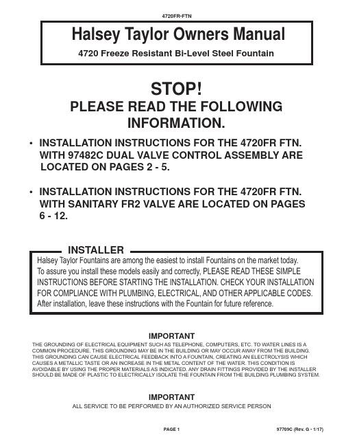
4720 Freeze Resistant Bi-Level Steel FountainSTOP!PLEASE READ THE FOLLOWINGINFORMATION.• INSTALLATION INSTRUCTIONS FOR THE 4720FR FTN. WITH 97482C DUAL VALVE CONTROL ASSEMBLY ARE LOCATED ON PAGES 2 - 5.• INSTALLATION INSTRUCTIONS FOR THE 4720FR FTN. WITH SANITARY FR2 VALVE ARE LOCATED ON PAGES6 - 12.IMPORTANTTHE GROUNDING OF ELECTRICAL EQUIPMENT SUCH AS TELEPHONE, COMPUTERS, ETC. TO WATER LINES IS A COMMON PROCEDURE. THIS GROUNDING MAY BE IN THE BUILDING OR MAY OCCUR AWAY FROM THE BUILDING. THIS GROUNDING CAN CAUSE ELECTRICAL FEEDBACK INTO A FOUNTAIN, CREATING AN ELECTROLYSIS WHICH CAUSES A METALLIC TASTE OR AN INCREASE IN THE METAL CONTENT OF THE WATER. THIS CONDITION IS AVOIDABLE BY USING THE PROPER MATERIALS AS INDICATED. ANY DRAIN FITTINGS PROVIDED BY THE INSTALLER SHOULD BE MADE OF PLASTIC TO ELECTRICALLY ISOLATE THE FOUNTAIN FROM THE BUILDING PLUMBING SYSTEM.IMPORTANTALL SERVICE TO BE PERFORMED BY AN AUTHORIZED SERVICE PERSON4720 Freeze Resistant Bi-Level Steel Fountainwith 97482C Dual Valve Control AssemblyIMPORTANT! INSTALLER PLEASE NOTEDo not pull up on lines coming out of the PVC column. Use the nylon strap (ref. 17) to lift the unit to prevent damage to the valve.General Installation Tips1. Be sure to fl ush water supply line before you connect it to the inlet fi tting on Freeze Resistant Valve System.2. There are two drain lines required for this unit. One for the drinking fountain basin drain and one for the valve/water supply line system. The bowl drain is the 3/4" PVC fi tting at the bottom of the 6" PVC tube and the valve drains through the small holes in the PVC cap. Provide ample drainage for these two items. It's always better to have too much then not enough.3. The column (6" PVC tube) must remain vertical. Be sure it remains vertical when backfi lling the excavating trench.4. When the concrete pad, for mounting the fountain, is poured, be sure to allow adequate space around the top of the column so that the fl exible cap may beremoved for servicing the valve.5. We recommend that the top of the column be fl ush or slightly above the top height of the concrete pad.6. You should test the unit before you backfi ll. Simply blow on the clear, small diameter tubing. A steady stream should fl ow from the braided tubing line. When airpressure is removed from the clear tubing the water stream should stop.7. Once you have tested the valve, backfi lled the hole and poured the concrete mounting pad you are ready to set the fountain. After bolting the fountain in placeconnect the air control valve tubing, supply water tubing and drain lines. The water supply line must have a straight run from the basin bubbler down to the control valve. If a straight run is not maintained water will become trapped and freeze leaving the unit inoperable. Test the fountain again. If it fails to work, the air control line may be kinked or connected improperly. Be sure to keep water out of the air control line.8. These products are designed to operate on 20 PSI to 105 PSI supply line pressure. If inlet pressure above 105 PSI, a pressure regulator must be installed in thesupply line. Any damage caused by reason of connecting this product to supply line pressure lower than 20 PSI or higher than 105 PSI is not covered bywarranty.LEGENDA = ACCESS PANELB = REMOVABLE BOTTOM COVERC = 1" PVC DRAIND = PRESSURE FITTING 1-1/4" x 3/4"E = CONNECTOR 1-1/4" TO 1-1/4"F = 1-1/4" DRAIN TUBEG = AIR CONTROL LINEH = 1/4" WATER LINEJ = CONNECTOR FOR AIR CONTROL LINESITE PREPARATION DETAIL FOR THE4720FR FTN. WHEN USING 97482C DUAL VALVE CONTROL ASSY.FIG. 12222 CAMDEN COURT OAK BROOK, IL 60523 630.574.3500 PRINTED IN U.S.A.7, 132910414530213428257, 138292533102835272716181161552232283117121514213334241519111261515303FIG. 3Stream HeightAdjustmentDetail2329Stream HeightAdjustment20, 263Dual Valve Assy.(Item 36)38FOR PARTS, CONTACT YOUR LOCAL DISTRIBUTOR OR VISIT OUR WEBSITE Halsey Taylor Owners Manual4720 Freeze Resistant Floor Mounted Steel Fountainwith Sanitary FR2 ValveIMPORTANT! INSTALLER PLEASE NOTETubing must be cut to the right length. Do not coil any excess tubing or it will cause valve to malfunction.General Installation Tips1. Prepare trench for water supply and waste drain lines. The hole should be deep enough to accommodate the PVC column.Additional porous fi ll and drain pipe may be required due to local ground conditions. Cut the PVC column to fi t desired burydepth. Set PVC column in excavating pit.2. Lay drain lines and water supply lines. Provide service shut-off valve for maintenance. Flush the water supply line beforeattaching to the shut-off valve.Other Notes:• The details on the attached pages show a suggested installation method. Depending on the climate and environmental conditions the suggested installation may be modifi ed.• Overall - for the freeze resistant to function properly the valve must be installed in a non-freezing area.SUGGESTED SITE PREPARATION DETAIL FOR THE 4720FR FTN. WHEN USING THE SANITARY FR2 VALVE1-1/2 DRAIN TUBE SUPPLIED WITH FTN.AIR GAP ASSY.SUPPLIED WITH VALVE1-1/2 DRAIN TUBE SUPPLIED BY INSTALLERDetail ALEGENDA = ACCESS PANEL ( 8" X 10" )B = REMOVABLE BOTTOM COVERFIG. 2INSTRUCTIONS FOR CONNECTING TUBES FROM VALVE TO FOUNTAIN(S)Step 1 - Insert the 1/8” O.D. tube(s) (Labeled A & B) into the connector(s) (provided with fountain). Insert the 1/8” O.D. tube(s) coming from the fountain(s) push button actuator(s) into the connector(s). Trim any excess length.Step 2 - Secure the 1/8” O.D. tube(s) (Labeled C & D) to the waste line assembly. This line is a vent line and should be open to the air.Step 3 - Insert the 1/4” O.D. tube(s) (Labeled E & F) into the 1/4” union(s) (provided with valve assembly). Insert the 1/4” O.D. water lines coming from the fountain(s) into union(s). Trim any excess length.Step 4 - Insert the 1/4” O.D. tube (Labeled G) into the air gap assembly.Step 5 - Secure the 1/4” O.D. tube (Labeled H) to the waste line assembly. This line is a vent line and should be open to the air.FOUNTAIN CONNECTIONSLABEL A(ON/OFF CONTROL LINE FOR BUBBLER ONE)LABEL F (WATER LINE)LABEL G (DRAIN LINE)LABEL E (WATER LINE)LABEL B(ON/OFF CONTROL LINEFOR BUBBLER TWO)LABEL C (VENT LINE)LABEL H (VENT LINE)LABEL D (VENT LINE)FOUNTAIN CONNECTIONSFIG. 3PLUMBING CONDUIT (BY INSTALLER)TO VALVEFIG. 6166324121571771475, 137SEE DETAIL BDETAIL B88881517FIG. 4FIG. 5Stream Height AdjustmentPAGE 1197709C (Rev. G - 1/17)1110919181FIG. 7FIG. 8FIG. 9DESCRIPTION11017544389028424C 40045C 45807C 50986C 56082C 56092C 56123C 56185C 56187C 56203C 56235C 61313C 70817C 70828C 75639C 75642C 75652C 75653C 70683C12345678910111213141516171819NSPART NO.Hex Nut - 3/8-16Bracket - Regulator Holder Hex Nut - 1-5/16Dual ValveRegulator Holder Regulator NutPoly Tubing - 1/4” (Cut To Length)Poly Tubing - 1/8” (Cut To Length)CanisterTrap - Adaptor 1-1/2Air Gap Assy.Fitting - 1/2” Union w/Strainer RegulatorFitting - Elbow 1/4 Stem x 1/4 Tube Fitting - Connector 1/4 x 1/4 NPTF Fitting - Elbow 1/4 x 1/4 NPTFFitting - Adaptor 1/4 NPT x 1/2 NPT U-BoltNylon Strap - 6 ft.Fitting - Union 1/4ITEM NO.PARTS LISTthe Sanitary FR2 ValvePAGE 1297709C (Rev. G - 1/17)TroubleshootingInsuf fi cient Bubbler Flow: Check that the shut-off valve is wide open. Verify minimum20 PSI supply pressure. Clean inlet strainer screen located in the valve body. Clean rubber ori fi ce in fl ow control located below frost line in bushing between barb fi tting and valve.No Flow: Check for leaks in the air tubing going from the push button to the valve. Make sure the air tubing compression nut is hand tight. Disconnect air tube from push button. Place fi nger over air outlet. Push button to test diaphragm. Tighten diaphragm cap screws. Replace diaphragm if necessary.Continued Insuf fi cient or Varied Height of Bubbler Flow:• Replace fl ow control.• Check for kinks in the tubing.• Remove the cleanout plug from the PVC column. Remove the valve assembly from thePVC column by carefully pulling up on the strap and connecting tubing at the same time. Pressure test the valve assembly for leaks. Check stream height from the bubbler. Stream height is factory set at 35 PSI. If supply pressure varies greatly from this, adjust the screw on the regulator (Item 13, Fig. 5, Page 10). Clockwise adjustment will raise stream and counter-clockwise adjustment will lower stream. For best adjustment stream height should be approx. 1-1/2" (38mm) above the bubbler guard. Replace the valve into the PVC column. Make sure the supply hose coils into the bottom of the PVC column without any kinks and double check that the valve is positioned fully at the bottom of the PVC column. Cap the PVC column.Continuous Bubbler Flow: Insure that push button is not obstructed and springs back to normal position. Remove four screws which secure plastic diaphragm block to valve body. Pull plastic and rubber diaphragm assembly out of valve body. Locate tiny hole in rubber diaphragm just under lip of plastic part. Clean debris from this hole. Inspect valve seat for grooves. If valve seat was OK and diaphragm hole was free from debris, inspect rubber button located at center of fl oating steel disc in valve diaphragm block assembly. If button is worn, turn disc over or replace it. If diaphragm and seats are in good condition, stretch spring slightly. Spring is located behind fl oating stainless steel plate. Insure that air bleed port on valve plastic block assembly is not plugged.FOR PARTS, CONTACT YOUR LOCAL DISTRIBUTOR OR VISIT OUR WEBSITE 2222 CAMDEN COURT OAK BROOK, IL 60523630.574.3500PRINTED IN U.S.A.Included with Sanitary FR2ValveFIG. 1044453842232128272125, 3132333324293733303536234233333945444134432722204028372122293024203326264025, 312110014714056010032274056010157054056015013C 15014C 11054494255011086864255016027050864017070504283028091C 40045C 45851C 40250C 45403C 45476C 45830C 45842C 45663C 55913C 56121C 60098545164066346C 70683C 75534C 75588C 75589C 75520C 75565C 75596C 56092C 56123C 75539C2021222324252627282930313233343536373839404142434445NS NS NS NS NS NSDrain Gasket GasketDrain GasketBubbler Tube Assy.Retaining NutSet Screw #8-32 x .125Socket Head Screw #10-24 x .75Strainer Plate BasinNameplate Insert Hex Nut 1-5/16"BubblerTailpipe 1-1/4" x 5-3/8"Push Button Actuator Drain Tube Fountain Body Access PanelPush Button Sleeve Drain AdapterDrain Elbow 1-1/4"Drain Plug Assy.Drain Tube Union 1/4Pinned Torx Screw #10-24Slip Joint Nut 1-1/4"GasketBit - Pinned Torx T-25Fitting - Double Male Connector Paint Touch-up (Pen)Poly Tubing - 1/4" (Cut To Length) - To Bubbler Poly Tubing - 1/8" (Cut To Length) - To Actuator Allen WrenchITEM NO.PART NO.PARTS LISTDESCRIPTIONthe 4720FR Fountain。
不一样的品味 法国摩托车品牌Voxan

CULTURE摩托文化•史话—不一样的品诵法国摩托车品牌Voxan世界摩坛中,法国向来名不见经传,除了处产濟著称的标致公司兼生产踏板车之外,似乎没有听过明腔出名的厂家。
确实,虽然法国人喜欢摩托车,虽然巴黎常常是巴黎一达喀尔拉力赛的起点或终点,但是这个国度确实不以生产摩托车著称。
不过,你可干万别就此小觑他们的想象力,以性格浪漫著称的法国人一旦做起摩托车来,就令人刮目相看了,我们这次就来看看Voxan摩托车公司的独特美学追求。
文丨蓝勇72NOVEMBER2020艰托车杂志《摩托车》杂志2020NOVEMBER73摩托文化•史话创THRF客气地说,至少90%以上的摩友对于这家法国摩托车公司所知甚少,这里我们先作个简要介绍。
\oxan的历史并不长,成立于1995年,总部位于法国伊苏瓦尔。
1997年\oxan推出了最早的摩托车原型,两年之后生产了Roadster,随后又推出Cafe:Racer、Scrambler、Street Scrambler>\BI、Black Magic>Black Classic、Charade Racing等车型。
\oxanW着强烈的自我意识,推出的车型堪称艺术品。
让我们看看2(XX)年推出的\<*;ml(XX)Cale Racer—半截式导流罩、低矮的车把、单人坐垫、后座驼峰,发散出古典跑车的魅力;电喷\'型双缸发动机、IJremlx制动系统、倒立式前叉,提供现代摩托车的刺激和快感;将古典风格与现代性能融会,以奇特的法式风情来表达不一样的美学追求。
而且,Caf6Racer秀外慧中,不仅古典跑车风情浓烈,而且加速性能也很给力,0〜4()0m加速耗时11.5s,极速超过230km/h,特别是120km/h〜180km/h油门响应特别爽快,加速干脆利索!Cafe Racer搭载了液冷、夹角为72°的V型双缸发动机。
这台V2发动机釆用!)8.0nini X6(;.0inni的缸径和冲程,排量为!)9(>ml..再辅以10.5:1的压缩比,釆用玛雷利电子燃油喷射系统伺服后,可以输出最大功率74k\\(iMXXh-miii)和最大扭矩95N-m(65(X)”mi")。
CSESJ350 3

• Operating Manual • Warning Information• Parts ListCSESJ3503½ TonService JackMeets or exceeds ASME PALD-2005standards for performance & safety.Copyright © Professional Tool Products, 2009All rights reserveddeScripTionCSESJ350 service jack is a self-contained device designed for lifting, but not sustaining, a partial vehicular load. It consists of a frame with wheels and swivel casters supporting a mechanism that actuates a pivoting lift arm equipped with a saddle. It is designed for use by professional auto mechanics.***owner/uSer reSponSibiliTyThe owner and/or user must have an understanding of the manufacturer’s operating instructions and warnings before using this jack. Personnel involved in the use and operation of equipment shall be careful, competent, trained, and qualified in the safe operation of the equipment and its proper use when servicing motor vehicles and their components. Warning information should be emphasized and understood. If the operator is not fluent in English, the manufacturer’s instructions and warnings shall be read to and discussed with the operator in the operator’s native language by the purchaser/owner, making sure that the operator comprehends its contents.Owner and/or user must study and maintain for future reference the manufacturer’s instructions and pertinent warning information. Owner and/or user is responsible for keeping all warning labels and instruction manuals legible and intact. Replacement labels and literature are available from the manufacturer.inSpecTionVisual inspection should be made before each use of the jack, checking for leaking hydraulic fluid and damaged, loose or missing parts. Each jack must be inspected by a manufacturer’s repair facility immediately, if subjected to an abnormal load or shock. Any jack which appears to be damaged in any way, is found to be badly worn, or operates abnormally MUST BE REMOVED FROM SERVICE until necessary repairs are made by a manufacturer’s authorized repair facility. It is recommended that an annual inspection of the jack be made by a manufacturer’s authorized repair facility and that any defective parts, decals or warning labels be replaced with manufacturer’s specified parts. A list of authorized repair facilities is available from the manufacturer.OPERATIONIMPORTANT: Before attempting to raise a vehicle, check vehicle service manual for recommended lifting surfaces.1. To raise load: Close release valve tightly (by turning handle clockwise). DO NOT OVERTIGHTEN. Position jack under load so that saddle will contact load firmly and load is centered so it cannot slip. Operate jack handle until saddle approaches the load. Once again check to see that saddle is correctly positioned. Raise load to desired height. Place jack stands of appropriate capacity under the vehicle. DO NOT CRAWL UNDER VEHICLE WHILE LIFTING VEHICLE OR PLACING OR REMOVING JACK STANDS! Place jack stands at vehicle manufacturer's recommended lift areas that provide stable support for the raised vehicle.2. To lower load: Open release valve VERY SLOWLY (by turning handle counterclockwise). When release valve is opened, saddle and load will be lowered. Lower the vehicle slowly so as not to shock load the jack stands. Once repairs are completed, raise vehicle enough to remove jack stands. Lower vehicle very slowly.CAUTION: Keep hands or feet away from the hinge mechanism of the jack.hydraulic JacK mainTenanceIMPORTANT: Service jacks are designed for lifting purposes only; always support raised load with jack stands.regular mainTenance• Monthly or as necessary (depending on usage)1. Using a grease gun, add grease to grease fitting in the lift arm pivot shaft. (Use a multi-purpose NLGI type grease only.)2. Lubricate all linkages and pivot points. (Use white lithium spray grease only.)3. Remove handle; lubricate handle receptacle and handle end. (Use white lithium spray grease only.)4. Lubricate both rear casters, bearings and both front wheels. (Use white lithium spray grease only.)5. Tighten all accessible hardware.CSESJ350 Power Unit* Included in Seal Kit - RS35NSKOnly items identified by part number are available for purchase.RS35B20NPARTS BREAKDOWN - CSESJ350Item PartNo.No.DescriptionQty.1 RS35T01 Retaining Ring2 2 RS35T02 Washer 23 RS35B03 Front Wheel2 4 RS35B10 Rear Caster Ass'y.2 5 RS35T08 Hex Nut & Lock Washer2 6 RS35B11 Yoke Retaining Bolt & Washer 2 7 RS35T17 Handle Lever "B" 1 8 RS35T15 Handle Lever "A" 1 9 RS35009C Handle Bumper 1 10 RS35T13 Set Screw - Handle 1 11 RS35011C Handle Yoke 1 12 RS35B20N Power Unit Ass'y. 1 13 RS35T18 Universal Joint Ass'y.1 14 RS35B24 Block Linkage (incl. Split Pin, Ret. Rings) 1 15 RS35T12 Grease Fitting 1 16 RS35T04 Retaining Ring 2 17 RS35017 Saddle1 18 RS35018 Saddle Screw1 19 RS35019C Rubber Saddle Pad 1 20 RS35T19 Spring2Index PartNo.No.DescriptionQty.1 * Steel Ball 5 62 Large Pump Housing 13 * O-Ring 15 x 2.65 24 * Back-Up Washer 20 x 15.6 x 1.25 2 5 Big Pump Piston 16 Pump Spring 17 RSDC22N Dust Cover1 8 Washer1 9 RSRR27N Retaining Ring 201 10 RS35T18 Universal Joint Assembly1 11 * Steel Ball 6 1 12 * Brass Washer 2 13 Small Pump Housing 1 14 * O-Ring 10 x 2.65 2 15 * Back-Up Washer 15 x 10.6 x 1.25 2 16 Small Pump Piston 1 17 Pump Spring 1 18 RSDC15 Dust Cover1 19 Washer1 20 RSRR16 Retaining Ring 151 21 RS0FS37 Screw (incl. #22 o-ring)3 22 * O-Ring 7.1 x 1.8 3 23 Relief Valve Bolt 2 24 * Relief Valve Spring 2 25 * Plug 2 26 * Steel ball 4 1 27 Hydraulic Block 1 28 * Cylinder Seal 1 29 Cylinder 1 30 * O-Ring 31 x 4.6 1 31 * Gasket 1 32 Ram Bearing 1 33 Retaining Ring 30 1 34 Ram 1 35 Cylinder Nut 1 36 * O-Ring 29.6 x 3.5 1 37 * Gasket 1 38 Reservoir Tube 1 39 * Gasket 1proper STorageIt is recommended that this jack be stored in a dry location with all wheels touching the ground on a relatively level surface. TroubleShooTingImportant: Service jacks are self-contained devices used for lifting, but not sustaining, a partial vehicular load. In accordance with ASME-PALD standard, section 10-4.1.2 Load Sustaining Test: “A load not less than the rated capacity…shall not lower more than 1/8” (3.18mm) in the first minute, nor a total of .1875” (4.76mm) in 10 minutes.” Leak down within this range is considered normal operation and is NOT a warrantable defect.WARRANTY COVERAGECornwell Quality Tools Company (“Cornwell”) warrants against defects the hydraulic pump on this product for a period of TWO (2) YEARS from the date of original retail purchase. Cornwell Quality Tools Company (“Cornwell”) warrants against defects the balance of components on this product for a period of 90 days from the date of original retail purchase. Subject to the conditions and limitations set forth below, Cornwell will, at its option, either repair or replace any part of the product(s) that proves defective by reason of improper workmanship or materials.This warranty does not cover any damage to this product that results from accident, abuse, misuse, natural or personal disaster, or any unauthorized disassembly, repair, or modification. Repairs, disassembly and modification are only authorized to be made by Cornwell or a warranty service center approved by Cornwell. WARRANTY SERVICETo obtain warranty service, contact your Cornwell dealer.EXCLUSIONS AND LIMITATIONSTHIS WARRANTY AND THE REMEDIES SET FORTH ABOVE ARE EXCLUSIVE AND IN LIEU OF ALL OTHER WARRANTIES, REMEDIES AND CONDITIONS, WHETHER ORAL OR WRITTEN, EXPRESS OR IMPLIED. CORNWELL SPECIFICALLY DISCLAIMS ANY AND ALL IMPLIED WARRANTIES, INCLUDING, TO THE EXTENT PERMITTED BY APPLICABLE LAW, ANY WARRANTIES OF MERCHANTABILITY AND FITNESS FOR A PARTICULAR PURPOSE. IF CORNWELL CANNOT LAWFULLY DISCLAIM IMPLIED WARRANTIES UNDER THIS LIMITED WARRANTY, ALL SUCH IMPLIED WARRANTIES ARE LIMITED IN DURATION TO THE DURATION OF THIS WARRANTY. IN NO EVENT SHALL CORNWELL BE LIABLE TO THE PURCHASER OR TO THE USER OF A CORNWELL PRODUCT FOR ANY SPECIAL, INCIDENTAL OR CONSEQUENTIAL DAMAGES BASED UPON BREACH OF WARRANTY, BREACH OF CONTRACT, NEGLIGENCE, TORT, OR ANY OTHER LEGAL THEORY. SUCH DAMAGES INCLUDE, WITHOUT LIMITATION, EXPENSES, LOST REVENUES, LOST SAVINGS, LOST PROFITS, OR ANY OTHER INCIDENTAL OR CONSEQUENTIAL DAMAGES ARISING FROM THE PURCHASE, USE OR INABILITY TO USE THE CORNWELL PRODUCT.Some states do not allow the exclusion or limitation of incidental or consequential damages or exclusions or limitation on the duration of implied warranties or conditions, so the above limitations or exclusions may not apply to you. This warranty gives you specific legal rights, and you may also have other rights that vary by state. Repair kits and replacement parts are available for many Cornwell products, regardless of whether or not the product is still covered by a warranty plan.Cornwell Quality Tools Company667 Seville Road • Wadsworth, OH 44281-1094。
AVID FOD Receiver User's Guide

FOD Receiver User’s Guide Rev 3, 07/18/2013General DescriptionThe AVID FOD (Foreign Object Detection) Receiver is a standard WPC V1.1 wireless power receiver (5.0W) that has been calibrated and characterized to accurately measure and report received power information. This RX device is useful for testing transmitter devices, for characterizing and optimizingV1.1 (and newer) transmitter’s FOD functionality, and for doing Qi pre-compliance testing.Here are the main features of the AVID FOD Receiver:- Fully functional V1.1 Qi Receiver- Uses “naked” RX coil as specified for TPR#5 in the WPC Part 3 spec. Coil is isolated from the electronics and mounted in plastic frame that mates with the foreign object holders for good alignment - Factory calibrated and characterized using calibrated AVID FOD Transmitter- Accurately measures and reports PPR (received power) values per WPC V1.1 spec- Calculates and sends additional 16-bit PPR values (proprietary packet 0x28) that can be decoded and reported using the AVID FOD Transmitter and AVID V1.1 Sniffer- Programmable PPR offset and internal loads (DIP switch settings)- External load board (included) has minimum, maximum and in-between loads for testing and characterizing transmitters and for running Qi pre-compliance tests- Supports internal loads up to 2.0 Watts in 0.25 Watt increments (DIP switch settings) and external loads up to 5.0 Watts maximum.AVID FOD Receiver, Top ViewAVID FOD Receiver, Side and Bottom ViewsAVID Receiver Load BoardBasic Setup and OperationTo operate the FOD Receiver, first set the DIP switches on top of the unit to program the internal loadand the PPR offset values (see below) as desired. The FOD receiver can be operated using internalloads up to 2.0 Watts, but AVID recommends leaving the Load DIP switches all off and connecting the external load board to the output screw terminals for testing because this will isolate the load from the receiver and keep the electronics at a more even temperature. Next, place the FOD Receiver on any Qi transmitter for characterization and testing.The “Power” and “Status” LEDs on top of the FOD Receiver indicate the operational state of the receiver. The Power LED will light solid blue as long as the receiver is receiving enough power from the transmitterto power up its internal electronics. The Status LED will light solid green when the receiver is receiving enough power to supply the internal or external load and to regulate its output voltage to +5.0V. Whenthe FOD Receiver is first placed on a transmitter, it connects a minimum internal load of 100 ohms (to ensure robust communications). Next the receiver adjusts its bridge voltage to about 5.8V and then connects the internal or external load and disconnects the minimum 100 ohm load. If an external load is connected to the terminal block on the receiver and current flow is detected through the output, all internal loads are disconnected otherwise the internal load programmed on the DIP switches is left connected.Once the load is connected, the receiver will send error messages to regulate the output to +5.0V +/- 5%. The FOD Receiver should operate normally on any Qi transmitter (base station). If the FOD Receiver is powered up and regulating its output voltage, the status LED will remain green or amber. If the FOD Receiver cannot regulate its output voltage the status LED will turn off. If an error occurs (see below) the status LED will blink red. To maintain good power measurement accuracy, always make sure theFOD Receiver is not operated on or near metal desks or other large metal objects during testing.Below are brief descriptions of the functionality supported by the FOD Receiver: Function DescriptionPower LED Solid blue when FOD Receiver receives sufficient power from the transmitter to power its internal circuitryStatus LED Solid green when FOD Receiver receives sufficient power from the transmitter to power its internal load and regulate to +5.0V +/-5% Solid amber when FOD Receiver receives sufficient power from the transmitter to power an external load and regulate to +5.0V +/-5% Blinking red indicates various error codes (see quick start guide below)VBRIDGE Pin Rectified bridge voltage measurement test point COMM Pin Communication modulator digital signal test point GND Pins Internal circuitry ground referenceTEST DIP Switches PPR offset multiplier (6 bits) 0 to 63. This value is multiplied by the PPR offset step size to get the resulting PPR offset value in mWCOMM DIP Switches PPR step size (2 bits). This value is multiplied by the PPR offset multiplier to get the resulting PPR offset value in mW00 = -5 mW, 01 = -10 mW, 10 = +5 mW, 11 = +10 mWLOAD DIP Switches Internal load (4 bits) 0 to 8 (positions 9-15 reserved)This value is multiplied by 0.25 to get the resulting internal load in Watts If external load >= 0.25W is sensed, all internal loads are switched offTerminal Block For connecting external loads. When operating properly the FOD Receiver will provide +5.0V +/- 5% at this outputExternal Load Board Can be used to connect and switch on/off various external loads for characterizing V1.1 transmitters and running FOD pre-compliance testsV1.1 Transmitter (Base Station) FOD CharacterizationV1.1 QI compliant transmitter (base station) product developers can use the AVID FOD Receiver tool and the AVID external load board (or user supplied load) to characterize and adjust the transmitter power measurements. The FOD Receiver has been characterized using the AudioDev WPC approved V1.1 Test Transmitter and the results show good correlation between transmitted power and received power to within about 50 mW accuracy over a 0.25 W to 6.0 W load range.If the transmitter under test has a means of providing an indication of its transmitted power values during power transfer, then it is possible to use the AVID FOD Receiver to characterize the transmitter’s power loss measurements and FOD thresholds.To use the AVID FOD Receiver to characterize a transmitter, use the following procedure:1) Connect the external load board to the FOD Receiver terminal block and switch on the 0.25 Wload only. The on position for the switches is toward the edge of the load board.2) Place the FOD Receiver on the transmitter, center aligned, and record the transmitted power andreceived power values. If the transmitter does not already provide the received power values to the user, the AVID Qi Sniffer V1.1 can be used to capture the received power values including16-bit high resolution values reported by the AVID FOD Receiver.3) Repeat step 2 at several external load points such as at 1.0 W increments up to 5.0 W.4) Plot the received power vs. transmitted power values for each load point. The data should showgood correlation. If the difference is greater than 100 mW at any of the load points, makeadjustments to the transmitter to improve the power measurements.Base Station Qi Pre-Compliance TestingV1.1 QI compliant transmitter (base station) product developers can use the AVID FOD Receiver tool, the AVID external load board (or electronic load), and a set of WPC defined Foreign Objects to run Qi FOD Part 3 pre-compliance tests. AVID Technologies supplies (separately) the WPC defined foreign objects with an alignment frame and spacers that can be used for this testing.The Part 3 Base Station FOD compliance tests use two test receivers: TPR#5 and TPR#6. These receivers use a low-loss coil with no shield to minimize parasitic losses.TPR#5 is configured to output 5.0V +/-20% and to use a received power window size of 64 ms and a window offset size of 16 ms. TPR#5 is also configured to over report its received power values by 235 mW. During the WPC interim extension period in effect until May 2014, TPR#5 shall instead over report its received power values by 35 mW:TPR#5 PPR = (PPM+235)TPR#5 (INT) PPR = (PPM+35) ** Use this equation during the WPC interim periodPPM is the actual received power determined by the test receiver by measuring its load power and adding estimated parasitic power losses.TPR#6 is identical to TPR#5 except TPR#6 is configured to under report its received power values by 15 mW. During the WPC interim extension period in effect until May 2014, TPR#6 shall instead under report its received power values by 115 mW.TPR#6 PPR = (PPM-15)TPR#6 (INT) PPR = (PPM-115) ** Use this equation during the WPC interim periodBase Station Thermal Compliance TestingThe Part 3 Base Station FOD thermal compliance tests consist of measurements that check the temperature rise (at +25 deg C ambient) of four different WPC defined foreign objects while they are placed between the test receiver (TPR#5) and the base station during power transfer. Each object has an allowed temperature limit as defined in the table below.WPC Defined Foreign Objects:LimitObject Configuration Temperature#1 Steel disc centered 60 deg C#2 Aluminum ring centered 60 deg C#3 Aluminum foil centered 80 deg C#4 Steel disc offset 15.5 mm 60 deg CIf any of the foreign objects reaches or exceeds the temperature limits above during testing, the transmitter’s FOD measurements, thresholds, or reaction time may need to be adjusted to meet compliance.To use the AVID FOD Receiver to emulate TPR#5 and run the foreign object thermal pre-compliance tests on a base station, use the following procedure:1) Set the DIP switches on the AVID FOD Receiver to emulate TPR#5 as follows:TEST = 000111 (PPR offset multiplier = 7)COMM = 10 (PPR offset step = +5 mW)LOAD = 0000 (no internal load)2) Connect the external load board to the FOD Receiver and switch on the 0.25W (100 ohm) loadonly on the far left of the load board near the terminal block connector.3) Connect foreign object #1 (steel disc) K-type thermocouple connector to a suitable thermometeror DMM that can measure temperature of a K-type thermocouple.4) Fit the clear plastic alignment frame on top of the foreign object holder.5) Place the foreign object and alignment frame on the base station under test and align the centerof the foreign object holder with the center of the base station transmitter coil. The AVID foreign object holders have score marks that indicate the center lines.6) Place the AVID FOD Receiver in the alignment frame on top of the foreign object and make surethe receiver and foreign object are still center aligned with the transmitter coil.7) Increase the load on the external load until the transmitter hits its power loss (FOD) threshold andterminates (or lowers) its transmitted power. If you are using the AVID supplied external loadboard, leave the 0.25W load switched on, switch on the variable (0.24 W to 1.38 W) load, andslowly adjust the potentiometer until right at the point the power loss threshold is hit.8) Reduce the external load by 50 mA. If you are using the AVID supplied external load board thiscan be accomplished by switching off the 0.25W (100 ohm) load.9) Run the transmitter for 10 minutes (or until the transmitter terminates power transfer) and recordthe temperature of the foreign object.If the transmitter terminates power transfer before 10 minutes during any of these tests, repeat steps 6 and 7 above and reduce the load slightly until the transmitter runs for 10 minutes OR until the minimum load of 0.25 W (50.0 mA) is reached. At the minimum load, if the transmitter still terminates power before 10 minutes, the temperature of the object is recorded at the point where power transfer was terminated. The steps above are repeated as follows:- Using object #1 with 2.0 mm spacer placed between the foreign object and the AVID FOD receiver- Using object #1 with 5.0 mm spacer placed between the foreign object and the AVID FOD receiver- Using foreign object #2- Using foreign object #3- Using foreign object #4The steel disc objects present lower power losses and temperature rises than the other objects. For the steel objects, the thermal test may run for the full 10 minutes. The transmitter FOD power loss threshold should be set to keep the temperature of the objects below the limit at the end of the 10 minute test.The aluminum foil and ring objects present higher power losses and temperature rises than the steel discs. For these objects, even at the minimum 50 mA load the thermal test may not run the full 10 minutes before the transmitter reaches its FOD power loss threshold. In this case the transmitter FOD threshold and reaction time should be adjusted to keep the foreign object temperature below the limit when the threshold is reached and the transmitter either terminates or reduces power.If the transmitter can be adjusted to keep the foreign objects below the temperature limits for all of the above tests, then the product will likely pass the FOD thermal compliance tests at an approved Qi compliance lab. If not, adjust the transmitter FOD power loss thresholds and reaction time accordingly.Base Station Guaranteed Power Compliance TestingThe Part 3 Base Station FOD guaranteed power compliance test consists of a measurement that checks to make sure the base station under test can deliver 5.0 Watts to a test receiver (TPR#6) that has no foreign object present, but is simulating power loss into a foreign object by under reporting its received power.To use the AVID FOD Receiver to emulate TPR#6 and run the guaranteed power pre-compliance tests on a base station, use the following procedure:1) Set the DIP switches on the AVID FOD Receiver to emulate TPR#6 as follows:TEST = 010111 (PPR offset multiplier = 23)COMM = 00 (PPR offset step = -5 mW)LOAD = 0000 (no internal load)2) Connect the external load board to the FOD Receiver and switch on the 0.25W load only.3) Place the FOD Receiver on the base station and make sure it is center aligned with thetransmitter coil. Wait until the base station begins power transfer.4) Switch on the 1W load on the external load board. Allow the base station to continue powertransfer for 10 seconds.5) Switch on the 2W load on the external load board. Allow the base station to continue powertransfer for 10 seconds.6) Switch on the 3W load and switch off the 0.25W and 1W loads on the external load board (total =5W load). Allow the base station to continue power transfer for 5 minutes.7) Measure the voltage at the terminal block output on the FOD Receiver and make sure it isbetween 4.75V and 5.25V (regulation tolerance of the FOD Receiver).If the voltage measured in step 7 is between 4.75V and 5.25V, then the product will likely pass the FOD guaranteed power compliance tests at an approved Qi compliance lab. If the voltage is not between4.75V to5.25V, make adjustments to the base station device to improve the power transfer performance and repeat the tests above.NOTE: AVID FOD TOOLS ARE NOT APPROVED FOR FINAL QI COMPLIANCE TESTING. THEY ARE DESIGNED TO BE USED FOR DEVELOPMENT AND PRE-COMPLIANCE TESTING BY CUSTOMERS DESIGNING and PROTOTYPING WPC V1.1 WIRELESS POWER PRODUCTS.AVID FOD Receiver Quick Start Guide:Quick Start Guide ***************************SYSTEM MONITORING:VBRIDGE: (5.0V +/-0.5V)Receiver DC Bridge VoltageCOMM. (0 -3.3V Logic)Modulation Signal5V, 0-1A OUTPUT:Internal load is disabledwhen external load (>0.25W)is connected.CONFIGURATION SWITCHES:TEST Position 1-6PPR offset multiplierLOAD Position 1-4Selects internal load0-2W, in 0.25W StepsCOMM Position 5PPR offset polarityPosition 6PPR offset step sizeAll switches can be changedduring run time.STATUS LED:©2013 AVID Technologies, Inc. All rights reserved.FOD Receiver。
民航飞行人员英语等级考试(ICAO)模拟题-第三套-306

第三套1 the greater the weight of the aircraft, the more intense will be the wake turbulence,particularly when it affect the aircraft has a short wing span than other general aircraftQ: what phenomenon does this statement refer to这个不会What phenomena does this statement refer to?Victor turbulenceWake turbulenceWeek turbulenceWeak turbulence2 Nicad battery are frequently used in turbo aircraftQ According to the statement, what type of aircraft is more likely to have a NiCad battery?没有题目According to the statement, what type of aircraft is more likely to havea NiCad battery?Rocket Aircraft.Supersonic Aircraft.A Glider.Aircraft with a propeller.3 scanning the sky for other aircraft is important in avoiding mid-air collision, particularly flyunder visual flight rulesQ: what is the reason for scan the sky for other aircraftWhat is the use to scan the sky for other aircraft, especially while flying under VFR?1..To look for other aircraft clearly.2.To prevent collisions in the air.3.To avoid military collisions.To avoid mid-air incursion.4 pilots are urged in own interests to request assistance from the emergency services as soon asthere is any doubt about the safe conduct in the sky.Q: when should pilot request assistance from emergency departmentWhen should pilots request assistance from emergency service?When they are urged to do so.When they have no interest in handling the flight.When they could handle the situation.When they are not sure of the flight safety.5 when flying in app in a strong gust headwind, the Vraf should be adjusted by half of the headwind and full gust speed.In windy conditions, how much should Vref be adjusted by during an approach?Full headwind and full gust.Full headwind and half gust.Half headwind and full gust.Only headwind.6 a flight direct to __are from the primary flight instrument are the Chevron indicator, or a pair of vertical horizontal bars, both Chevron and bar flight indicator are command the plane, which means by flying towards them, they will regain or maintain the flight progress.Q: what is the main topic in this statementWhat is the main topic in the statement?Flight Directors.Primary flight instruments.Horizontal bars.Chevron Indicators.(v型指示仪)7 AFR145 is currently on route from Paris to Heathrow , the aircraft was descending to 3000ft and requesting direct to TLA, air traffic control didn’t grant their request due to conflicting aircraft at 3000ftQ: why did air traffic control denied the request from AFR 145Why did Air Traffic Control deny the request of Air France 145?Military activityConflicting TrafficTerrainWeather conditions8 forecast condition in shanghai airport this morning, expect ceiling 900m, broken with 3000movercast, visibility 4000m, reducing in 1000m due to strong wind shower, wind 320 at 10meters per second, gust 15 meters per second.Q: which statement is not correctWhich statement is not correct?Ceiling is 900m brokenVisibility is reducing to 3000m overcastVisibility is 4000mThere are heavy rain showers9 the localizer transmitter is situated on the extended runway centerline, the localize beennormally found to centerline the runway and extends along the app path from 25 miles with 40 ILS channels, with a frequency range of 108.0 to 119.15 mhz to provide pilots with course guidanceQ: what is localizer used for这个不会What is localizer used for?Horizontal guidanceBoth longitudinal and lateral guidanceVertical guidanceLongitudinal guidance10 week, while taxing to the runway, we got a hydraulic low quantity warning, after confirmingwe are losing fluid, we stopped and call for a tug, unfortunately , we had to wait for nearly an hour before it came, by the time we finally changed the plane, we were 2 hours late.How did they get back to the gate?It took nearly an hour.They used a tug.They went back on one engine.They had to shut down.11 AFR 215, FL310 is not available at the moment, the alternative is FL 350 advise.Q: which statement is trueWhich statement is true?FL350 is not available.FL310 and FL350 are not available.FL310 is now available.FL350 is now available.12CCA412, heavy, cleared for takeoff, RW 23L, wind 220 at 15 knots.Q: which runway is CCA412 used to takeoffWhich runway is Air China 412 using to take off?1.15 right.2.23 left.3.15 left.23 right.13Speed bird 480, flames coming from your No. 3 engine on takeoff, please adviseRoger, declare an emergency , request immediate return.Q: why are they declaring emergencyWhy are they declaring an emergency?engine firemissed approachrequesting return to airportwarning light indication14CCA101, due traffic congestion, make a 360 turn left at your present position.Q: what is the aircraft expected to doWhat is the aircraft expected to doTo lose heightTo turn left at 360To lose timeTo speed up15CCA982, 22km from touch down, turn right heading 33o, cleared for ILS runway 36L, report established.Q: which of the following information is not true-15 Which of the following information is not true?Report established.Cleared for IGS runway 36L.3.22km from touchdown.Turn right heading 330.16 Speed bird 639, turn left heading 130 to offset your original track, the latest weather forcast reports CBs is building up on your route, fly with caution, after go round them, resume own navigation.Turn left heading 130 to detour the CB, speed bird 639.. What does the controller's instruction to BAW639 indicate?What does the controller's instruction to BAW639 indicate?It will turn left to resume its own navigation .It is expected to meet CBs on its original route.It will resume its own navigation after left turn.It will offset its path to encounter CBs.17United 755, ceiling 250 feet variable, visibility 2200 in fog, advise go around.United 755United 755, no contact minimum, overshooting.What is the reason for advised going around?Gear problem.Undershooting.Ceiling.Crosswind.18AFR 201, cancel landing clearance, runway 23L due to disable aircraft, change to RW 23R, cleared to land RW23R,AFR201, unable to land Rw23R due to braking problem. We need a longer runway.AFR201, go around immediately, turn left heading 140 to vector the ILS runway 23L, climb and maintain 4000ft, the runway will be available in 5 minutes.Why can't they land on R/W 23 R?They need a longer runwayThey can't extend their flapsThey have to go aroundR/W 23 L is blocked19United 350, we can’t hold any longer, we have a serious old passenger on board, United 350, leave the holding pattern, flight heading 050,Flight heading 050, united 350, request first aid after landingRoger, United 350‘What will be the immediate need after landing?1.A shuttle busA leader-vanMedical service4.A follow-me car20 United 655, we have a serious fuel leak, we are returningUnited 655, descend and maintain 3300m,Leaving 5400m to 3300m, United 655United 655, do you required emergency services upon landingAffirm, United 65520 What is the problem with the aircraft?Low enduranceFuel shortageFuel leakLack of fuel。
三岵Siemens SIRUS 3RW30 31软启动器说明书

Siemens LV 1 · 20066■OverviewVarious versions of the SIRUS 3RW30/31 soft starters are available:•Standard version for fixed frequency three-phase motors, sizes S00, S0, S2 and S3•Version for fixed-speed three-phase motors in a 22.5mm enclosure•Special-purpose version 3RW31 for Dahlander motors only in size S0•Version for soft starting single-phase motors of sizes S0, S2 and S3.SIRIUS 3RW30/31 for three-phase motorsSoft starters rated up to 55kW (at 400V) for standard applica-tions in three-phase networks. Extremely small sizes, low power losses and simple commissioning are just a few of the many ad-vantages of this soft starter. The special feature of the 3RW31 series is that it allows independent definition of two separate acceleration ramps (Dahlander motors).SIRIUS 3RW30 for single-phase motorsThe additional version for standard applications in single-phase networks. Its voltage edge function reduces the motor's inrush current and effectively lowers the torque at the point of starting up. The load and the supplying network are thus protected.■ApplicationThe SIRIUS 3RW30/31 solid-state soft starters are suitable for soft starting and stopping of three-phase asynchronous ma-chines.Due to two-phase control, the current is kept at minimum values in all three phases throughout the entire starting time. Due to continuous voltage influencing, current and torque peaks, which are unavoidable in the case of wye-delta starters, for instance, do not occur.Application areas •Fans •Pumps•Building/construction machines •Presses •Escalators•Transport systems•Air conditioning systems •Ventilators•Assembly lines•Compressors and coolers •Operating mechanisms6■Selection and ordering dataSelection of the soft starter depends on the motor’s ratedcurrent.3RW30 03-2CB543RW30 25-1AB14*You can order this quantity or a multiple thereof.6/6Siemens LV 1 · 2006Siemens LV 1 · 200661)Rated control supply voltage U s 110 ... 230 V AC/DC.Selection of the soft starter depends on the motor’s rated current.The SIRIUS 3RW3 solid-state soft starters are designed for easy starting conditions. J Load < 10 x J Motor . In the event of deviating conditions or increased switching frequency, it may be neces-sary to choose a larger device. Siemens recommends the use of the selection and simulation program Win-Soft Starter.See LV 1 T for information about rated currents for ambient temperatures >40 °C.Ambient temperature 40 °C Ambient temperature 50 °CSize DT Order No.Price per PUPU (UNIT, SET, M)PS*PG Weightper PU approx.Rated opera-tional current I e Rated output of three-phase induction motors for rated operational voltage U e Rated opera-tional currentI e Rated output of three-phase induction motors for rated operational voltage U e115 V 230 V 400 V 500 V 115 V 200 V 230 V 460 V 575 V AkWkWkWkWAhphphphphpkg12.5--3 5.5--11--337.5--S0 B 3RW31 24-1CB141 1 unit 1310.46816--47.5--14--3310--S0 B 3RW31 25-1CB141 1 unit 1310.47525-- 5.511--21--5515--S0B3RW31 26-1CB141 1 unit 1310.46412.5------7.511------7.510S0 B 3RW31 24-1CB151 1 unit 1310.46716------1114------1010S0 B 3RW31 25-1CB151 1 unit 1310.47625------1521------1520S0B3RW31 26-1CB151 1 unit 1310.47525 2.24----21 1.533----S0 A 3RW30 26-1AA121 1 unit 1310.439383 5.5----32255----S2 B 3RW30 35-1AA121 1 unit 1310.689755.511----6451010----S3B3RW30 45-1AA121 1 unit 1311.393*You can order this quantity or a multiple thereof.6Accessories1)With internal soft starter power supply.Forsoft startersSize Version DT Order No.Priceper PUPU(UNIT,SET, M)PS*PG Weightper PUapprox.Type kg3RW39 26-8A3RW39 36-8A3RW3 . 2.S0To increase switching frequencyand for device mounting in posi-tions different from the normal posi-tion.The fan is snapped into the enclo-sure from below.During operation, (control signalinput "IN" at potential A1), the fan isrunning. After a stop, the fan contin-ues to run for about another 60 min-utes.}3RW39 26-8A1 1 unit1310.008 3RW30 3.and3RW30 4.S2S3}3RW39 36-8A1 1 unit1310.030CoversTerminal covers for box terminals3RT19 36-4EA23RW30 3.S2Additional touch protection to befitted at the box terminals(2 units required per device)}3RT19 36-4EA21 1 unit1010.016 3RW30 4.S3}3RT19 46-4EA21 1 unit1010.023Terminal covers for cable lugs and bar connections3RT19 46-4EA13RW30 4.S3For complying with the phaseclearances and as touch protec-tion if box terminal is removed(2 units required per contactor)}3RT19 46-4EA11 1 unit1010.037Version FunctionalityFunctionsUse DT Order No.Priceper PUPU(UNIT,SET, M)PS*PG Weightper PUapprox.kg Sealable caps Forsecuringagainstunauthorized adjust-ment of setting knobsFor deviceswith 1 or2 COcontacts}3RP1 9021 5 units1010.004Push-in lugsfor screw mountingFor deviceswith 1 or2 COcontacts}3RP1 903110 units1010.002*You can order this quantity or a multiple thereof.6/8Siemens LV 1 · 20066/9Siemens LV 1 · 20066Note:The covers and connection modules listed here are also used for load feeders (3RV motor starter protector + 3RT contactor). For further technical specifications see Controls –> Contactors and Contactor Assemblies.For fuseless load feeders with size S00 soft starter, the link module has an integrated conductor routing.1)Computer labeling system for individual labeling of device labeling platesavailable from:murrplastik Systemtechnik GmbHFor soft starters Size Version DT Order No.Price per PUPU (UNIT, SET, M)PS*PGWeight per PU approx.Typekg3RA19 11-1A3RA19 21-1A3RA19 31-1AElectrical and mechanical linkbetween motor starter protector and soft starter.Single unit packaging 3RW30 1..S00 }3RA19 11-1AA001 1 unit 1010.0273RW30 2..S0 }3RA19 21-1AA001 1 unit 1010.0373RW30 3..S2 }3RA19 31-1AA001 1 unit 1010.0423RW30 4..S3 }3RA19 41-1AA001 1 unit 1010.090Multi-packs 3RW30 1..S00 }3RA19 11-1A 110 units 1010.0193RW30 2..S0 }3RA19 21-1A 110 units 1010.0283RW30 3..S2 }3RA19 31-1A 1 5 units 1010.0333RW30 4..S3}3RA19 41-1A15 units1010.072*You can order this quantity or a multiple thereof.6/10Siemens LV 1 · 200661)Without connectors for data and auxiliary power (yellow and black).2)With one connector each for data and auxiliary power (yellow and red).For busbar accessories, see SIVACON Switchgear,Distribution Systems and Cabinets –> 8US Busbar Systems.For soft starters Version DT Order No.Price per PUPU (UNIT, SET, M)PS*PGWeight per PU approx.Typekg3RK14 00-1KG01-0AA13RK14 00-1MG01-0AA1AS-Interface load feeder modulesFor standard rail mounting sizes S00 and S0. For mounting onto 40 mm or 60 mm busbar systems and SIRIUS stan-dard mounting rail adapters the matching support is required (see 3RK1 901-3GA00); the AS-Interface connectors for the data and auxiliary power cable (yellow and black) must be ordered separately (see 3RK1 901-0.A00)Rated opera-tional voltage U e2 inputs / 1 output 24 V DC 1)}3RK1 400-1KG01-0AA11 1 unit 1210.0974 inputs / 2 outputs A 3RK1 400-1MG01-0AA11 1 unit 1210.1002 inputs / 1 relay output 120/230 V AC 2)C3RK1 402-3KG02-0AA11 1 unit 1210.1243 inputs / 2 relay outputsB3RK1 402-3LG02-0AA111 unit 1210.143Manuals for AS-Interface load feeder modules German, English }3RK1 701-2GB00-0AA01 1 unit 1920.197French, ItalianA 3RK1 701-2HB00-0AA01 1 unit 1920.196Supports for AS-Interface load feeder modulesWidthFor mounting onto 3RA19 22-1A SIRIUS standard mounting rail adapter45 mmB3RK1 901-3GA0011 unit 1210.048Support with mounted power connector couplingPower connector sets 5-pole, 2.5 mm 2(1 package = 5 connec-tors and 5 couplings)C 3RK1 901-0EA001 5 sets 1210.1113RK19 01-0NA003RK19 01-0PA00AS-Interface connectors for data and auxiliary supply cablesColorWith insulation displace-ment terminals for 2 x (0.5 to 0.75 mm 2) flexible leadYellow C 3RK1 901-0NA001 5 units 1210.015BlackC3RK1 901-0PA001 5 units 1210.0153RA19 223RW30 1.Standard mounting railadapter for mechanical mounting of motor starter protector and contactor; can be snapped onto standard mounting rail or for screw mounting, suit-able for size S00}3RA19 22-1A1 5 units 1010.095Surge suppressors3TX7 462-3.RC elementsRated opera-tional voltage U eFor lateral snapping onto auxiliary switch or 35 mm standard mounting rail127 ... 240 V AC A 3TX7 462-3T 1 1 unit 1010.081*You can order this quantity or a multiple thereof.6/11Siemens LV 1 · 20066■More informationConfigurationThe 3RW solid-state motor controllers are designed for easy starting conditions. In the event of deviating conditions or in-creased switching frequency, it may be necessary to choose a larger device. For accurate dimensioning, use the Win-Soft Starter selection and simulation program.If necessary, an overload relay for heavy-starting must be se-lected where long starting times are involved. PTC sensors are recommended. This also applies for the smooth ramp-down be-cause during the ramp-down time an additional current loading applies in contrast to free ramp-down.In the motor feeder between the SIRIUS 3RW soft starter and the motor, no capacitive elements are permitted (e.g.no reactive-power compensation equipment). In addition, neither static sys-tems for reactive-power compensation nor dynamic PFC (Power Factor Correction) must be operated in parallel during starting and ramp-down of the soft starter. This is important to prevent faults arising on the compensation equipment and/or the soft starter.All elements of the main circuit (such as fuses, controls and over-load relays) should be dimensioned for direct starting, following the local short-circuit conditions. Fuses, switching devices and overload relays must be ordered separately. Please observe the maximum switching frequencies specified in the technical specifications.Power electronics circuit diagram 1)Status graphs1)Circuit diagram applies to sizes S0 and S2;for size S00, phase L3 is bridged;for size S3, phase L2 is bridged.Control with a PLCWhen a 3RW30 is operated with a triac output or thyristor output, the leakage current at the PLC output should be <1mA be-cause otherwise the 3RW30 will interpret the resultant voltage drop at the input as an "On command". As a corrective measure for PLC outputs with a higher leakage current, an RC element with >100nF and 220W can be connected in series between "IN1" and terminal "A2" of the 3RW30 (Order No.: 3TX7 462-3T see Selection and Ordering Data).Win-Soft Starter selection and simulation programWith this software, you can simulate and select all Siemens soft starters, taking into account various parameters such as mains properties, motor and load data, and special application requirements.The software is a valuable tool, which makes complicated, lengthy manual calculations for determining the required soft starters superfluous.You can order the CD-ROM under the following order number:Order No.: E20001-D1020-P302-V2-7400.You can find more information on the Internet at:/sanftstarter3RW31。
- 1、下载文档前请自行甄别文档内容的完整性,平台不提供额外的编辑、内容补充、找答案等附加服务。
- 2、"仅部分预览"的文档,不可在线预览部分如存在完整性等问题,可反馈申请退款(可完整预览的文档不适用该条件!)。
- 3、如文档侵犯您的权益,请联系客服反馈,我们会尽快为您处理(人工客服工作时间:9:00-18:30)。
C ommu nications World Wee k ly
外媒速览
本刊记者|高弋坤(编译)
近日,市场研究公司Infor m a 针对于无线宽带联盟进行的一项研究显示,得益于消费者使用智能手机和平板电脑上网需求的增加,当前W i -Fi 热点数量正在迅速增长,预计到2015年全球公共W i -F i 热点数量将较目前增长350%,达到580万个。
由于有助于分散无线数据流量,W i-F i 热点的部署对运营商来说至关重要。
对此,无线宽带联盟主席克里斯布鲁斯在近日的一次声明中说:“这一发现表明当前全球正在进入一个W i-F i 热点部署的黄金期,热点数量将会继续飙升。
”
据了解,仅中国移动一家运营商当前就计划部署100万个热点,日本第二大移动运营商K D D I 也计划在6个月内将其W i-F i 热点数量从1万个增加到10万个。
“固网运营商正在将宽带服务拓展到家庭和办公室之外,而W i -F i 则会对繁忙的移动宽带网络起到支撑作用。
”布鲁斯说。
与此同时,这一研究结果还表明,带动智能手机用户消费的是数据业务。
在亚太地区,智能手机连接到W i -F i 热点的频率已经远远超过了笔记本电脑的连接,越来越多的人正在选择通过智能手机连通网络。
亚洲电信
得益于消费者使用智能手机和平板电脑上网需求的增加,当前W i -Fi 热点数量正在迅速增长,预计到2015年全球公共W i -Fi 热点数量将较目前增长350%,达到580万个。
专注于i O S 操作系统漏洞的网络安全专家米勒是A ccuvant 实验室的一名研究员,近日,米勒制作出一种应用程序Inst a S t ock ,当苹果设备使用者下载该程序以后,该程序便可以偷偷下载别的恶意软件,从而盗取用户信息、发送短信或破坏数据。
据悉,目前已有数百人在他们的苹果设备上安装了该款免费应用。
不过,对于苹果来说,这却令其感到尴尬,因为其软件商店A pp S t ore 未能识别Inst a S t ock 其实是一款恶意程序,这意味着,当前A pp St or e 里面可能还存在着其他未能识别的恶意软件,这些软件利用一些手段通过了安全审核过程。
对此苹果公司表示不予以评论,但却同时在近期发给米勒一封电子邮件称,苹果宣布取消他为和开发软件
的权利,也将不再通过S 发布他的程序。
当前A pp St or e 里面可能还存在着其他未能识别的恶意软件,这些软件利用一些手段通过了安全审核过程。
路透社
Inst a S t ock 应用暴露iO S 安全漏
洞
外媒速
览
2015年Wi-Fi 热点将增长350
%
近期,微软、美国在线和雅虎三家公司对外宣布达成一项协议,三家公司中的任何一家都将允许其他两家公司向自己的广告投放客户销售未经预订的优质广告版面。
此举显然意在与谷歌和F acebook 等强劲对手争夺在线广告业务市场。
不仅如此,三家公司在声明中明确表示,这一协议的签订将大规模提高各自购买优质网络广告版面的效率,以获取更多广告客户和网站用户。
在这三家公司看来,他们之间的这一伙伴关系将会强化各自广告服务的需求和价值,同时还将为参与其中的出版商和广告客户带来更高的收益。
”
此外,根据协议条款,各公司将继续进行自主决策、提供差异化服务,并自行控制任何相互交流的网络广告业务的正常运营。
三家公司还称,他们还将基于各公司独特的差异化因素,在广告客户支出与合作出版商方面进行积极的相互竞争。
据了解,当前该协议仅在美国对三家公司共同有效,而在加拿大仅对雅虎和美国在线两家有效。
福布斯
微软、美国在线和雅虎三家公司对外宣布达
成一项协议,三家公司中的任何一家都将允许其他两家公司向自己的广告投放客户销售未经预订的优质广告版面。
此举显然意在与谷歌和F 等强劲对手争夺在线广告业务市场。
三巨头组成广告销售联盟
抵抗谷歌、Facebook
竞争
14
g k .c n
20111114i Ph on e i Pa d Ap p t o r e ac ebook。