现任明教教主笔记-CCNA Wireless 无线认证 1.4-Describing_Antennae
雷蛇那伽梵蛇专业版 高级用户指南说明书

雷蛇那伽梵蛇专业版高级用户指南如果可以称霸各种游戏,为什么还要只专精于其中一种?雷蛇那伽梵蛇专业版可以助你畅玩每一种游戏。
它是一款几经升级、采用最新雷蛇技术的无线鼠标。
它配备了三个可更换的侧板,分别提供三种不同的按键布局,助你在大型多人在线游戏 (MMO)、大逃杀或其他游戏中称霸全场。
目录1. 内含物品/要求 (3)2. 简要介绍 (6)3. 技术规格 (7)4. 入门指南 (8)5. 配置 RAZER NAGA PRO 雷蛇那伽梵蛇专业版 (14)6. 安全与维护 (34)7. 法律声明 (36)1. 内含物品/要求内含物品▪Razer Naga Pro 雷蛇那伽梵蛇专业版鼠标左键鼠标右键滚轮左倾单击—重复向下滚动右倾单击—重复向上滚动提高 DPI 等级降低 DPI 等级超顺滑鼠标垫脚Razer™ Focus+ 20K DPI 光学传感器配置文件指示灯配置文件按钮切换开关•Razer™ HyperSpeed Wireless 雷蛇极速无线 (2.4 GHz) 模式•关机模式•蓝牙模式鼠标底座*连接器(鼠标底座单独出售)无线 USB 接收器12 按键侧板(推荐用于 MMO 类游戏)6 按键侧板(推荐用于大逃杀)2 按键侧板(推荐用于一般性使用)▪Razer™ Speedflex 充电线▪USB 接收器适配器▪重要产品信息指南DPI 等级如下:400、800、1600(默认)、3200 和 6400。
你可以使用 Razer Synapse 雷云自定义 DPI 等级。
要求产品要求▪带一个可用 USB 端口或蓝牙 5.0 连接的电脑RAZER SYNAPSE 雷云要求▪Windows® 7 64 位(或更高版本)▪互联网连接,用于软件安装2. 简要介绍你现在拥有了一台非常棒的设备,并且附带两年的有限保修。
即刻通过/cn-zh在线注册,充分发挥设备的所有功能,并获得 Razer 雷蛇的独家福利。
Razer Naga V2 Pro游戏滑鼠说明书

進階指南專為主宰 MMO、大逃殺和 FPS 遊戲所設計,讓你成為更加強大的跨遊戲大師。
配備 3 個可更換側板、19+1 顆可編程按鍵、Razer HyperScroll Pro 滾輪和 Razer HyperSpeed Wireless 技術,擁有稱霸各種遊戲類型的力量。
目录1. 內含 (3)2. 使用需求 (5)3. 註冊即可享有保固 (5)4. 技術規格 (6)5. 設定你的 RAZER NAGA V2 PRO (7)6. 使用 RAZER NAGA V2 PRO (11)7. 透過 RAZER SYNAPSE 設定 RAZER NAGA V2 PRO (13)8. 安全與保養 (34)9. 法律條文 (36)1. 內含▪Razer Naga V2 Pro滑鼠左鍵滑鼠右鍵Razer™ HyperScroll 傾斜滾輪左傾斜點擊右傾斜點擊滾輪模式切換鍵▪自由捲動模式▪分段捲動模式DPI 循環切換按鈕*USB Type C 連接埠PTFE 材質滑鼠腳滑桿開關•藍牙模式•電源關閉模式•Razer™ HyperSpeed Wireless(2.4 GHz) 模式Razer Focus Pro 30K 光學感測器設定檔指示燈設定檔切換鍵蓋板***DPI 分段如下:400、800、1600(預設)、3200 及 6400;可使用 Razer Synapse 自訂。
**可替換為 Razer 無線充電接收器,以透過 Razer 滑鼠底座專業版進行無線充電(皆需另外購買)。
12 鍵式側板(建議玩大型多人線上遊戲 (MMO) 時使用)6 鍵式側板(建議玩大逃殺遊戲時使用)2 鍵式側板(建議日常用途時使用)▪USB Type A轉 USB Type C Speedflex 纜線▪Razer HyperSpeed Wireless Dongle + USB 傳輸轉接器▪重要產品資訊指南2. 使用需求產品需求▪ USB Type A 連接埠或藍牙連線功能RAZER SYNAPSE 需求▪ Windows® 10 64 位元(或更新版本) ▪ 網際網路連線(供下載安裝軟體)3. 註冊即可享有保固產品序號標示於此處。
摩耶V2416A系列无风扇、振动保护计算机产品介绍说明书

V2416A SeriesCompact,fanless,vibration-proof computers for rolling stock applicationsFeatures and Benefits•Intel Celeron/Core i7processor•Two hot-swappable2.5-inch HDD or SSD storage expansion trays•Dual independent DVI-I displays•2Gigabit Ethernet ports with M12X-coded connectors•2CFast sockets for OS backup•M12A-coded power connector•Compliant with EN50121-4•Complies with all EN50155mandatory test items1•IEC61373certified for shock and vibration resistance•Ready-to-run Debian7,Windows Embedded Standard7,and Windows10Embedded IoT Enterprise2016LTSB platforms•-40to70°C wide-temperature models available•Supports SNMP-based system configuration,control,and monitoring(Windows only)CertificationsIntroductionThe V2416A Series embedded computers are based on the Intel3rd Gen processor and feature4RS-232/422/485serial ports,dual LAN ports,and 3USB2.0hosts.In addition,the V2416A computers provide dual DVI-I outputs and comply with the mandatory test items of the EN50155 standard,making them suitable for a variety of industrial applications.The CFast socket,SATA connectors,and USB sockets provide the V2416A computers with the reliability needed for industrial applications that require data buffering and storage expansion.Most importantly,the V2416A computers come with2hot-swappable storage trays for inserting additional storage media,such as hard disk or solid-state drives,and support hot swapping for convenient,fast,and easy storage replacement. Each storage tray has its own LED to indicate whether or not a storage module is plugged in.The V2416A Series computers come preinstalled with a choice of Linux Debian7or Windows Embedded Standard7to provide programmers with a familiar environment in which to develop sophisticated,bug-free application software at a low cost.1.This product is suitable for rolling stock railway applications,as defined by the EN50155standard.For a more detailed statement,click here:/doc/specs/EN_50155_Compliance.pdfAppearanceFront View Rear ViewSpecificationsComputerCPU V2416A-C2Series:Intel®Celeron®Processor1047UE(2M cache,1.40GHz)V2416A-C7Series:Intel®Core™i7-3517UE Processor(4M cache,up to2.80GHz) System Chipset Mobile Intel®HM65Express ChipsetGraphics Controller Intel®HD Graphics4000(integrated)System Memory Pre-installed4GB DDR3System Memory Slot SODIMM DDR3/DDR3L slot x1Supported OS Linux Debian7Windows Embedded Standard7(WS7E)32-bitWindows Embedded Standard7(WS7E)64-bitStorage Slot CFast slot x2Computer InterfaceEthernet Ports Auto-sensing10/100/1000Mbps ports(M12X-coded)x2Serial Ports RS-232/422/485ports x4,software selectable(DB9male)USB2.0USB2.0hosts x1,M12D-coded connectorUSB2.0hosts x2,type-A connectorsAudio Input/Output Line in x1,Line out x1,M12D-codedDigital Input DIs x6Digital Output DOs x2Video Input DVI-I x2,29-pin DVI-D connectors(female)Digital InputsIsolation3k VDCConnector Screw-fastened Euroblock terminalDry Contact On:short to GNDOff:openI/O Mode DISensor Type Dry contactWet Contact(NPN or PNP)Wet Contact(DI to COM)On:10to30VDCOff:0to3VDCDigital OutputsConnector Screw-fastened Euroblock terminalCurrent Rating200mA per channelI/O Type SinkVoltage24to40VDCLED IndicatorsSystem Power x1Storage x1Hot-swappable2LAN2per port(10/100/1000Mbps)Serial2per port(Tx,Rx)Serial InterfaceBaudrate50bps to921.6kbpsFlow Control RTS/CTS,XON/XOFF,ADDC®(automatic data direction control)for RS-485,RTSToggle(RS-232only)Isolation N/AParity None,Even,Odd,Space,MarkData Bits5,6,7,8Stop Bits1,1.5,2Serial SignalsRS-232TxD,RxD,RTS,CTS,DTR,DSR,DCD,GNDRS-422Tx+,Tx-,Rx+,Rx-,GNDRS-485-2w Data+,Data-,GNDRS-485-4w Tx+,Tx-,Rx+,Rx-,GNDPower ParametersInput Voltage12to48VDCPower Connector M12A-coded male connectorPower Consumption(Max.) 3.3A@12VDC0.82A@48VDCPower Consumption40W(max.)Physical CharacteristicsHousing AluminumIP Rating IP30Dimensions(with ears)250x86x154mm(9.84x3.38x6.06in)Dimensions(without ears)275x92x154mm(10.83x3.62x6.06in)Weight4,000g(8.98lb)Installation DIN-rail mounting(optional),Wall mounting(standard) Protection-CT models:PCB conformal coating Environmental LimitsOperating Temperature Standard Models:-25to55°C(-13to131°F)Wide Temp.Models:-40to70°C(-40to158°F) Storage Temperature(package included)-40to85°C(-40to185°F)Ambient Relative Humidity5to95%(non-condensing)Standards and CertificationsEMC EN55032/24EMI CISPR32,FCC Part15B Class AEMS IEC61000-4-2ESD:Contact:6kV;Air:8kVIEC61000-4-3RS:80MHz to1GHz:20V/mIEC61000-4-4EFT:Power:2kV;Signal:2kVIEC61000-4-5Surge:Power:2kVIEC61000-4-6CS:10VIEC61000-4-8PFMFRailway EN50121-4,IEC60571Railway Fire Protection EN45545-2Safety EN60950-1,IEC60950-1Shock IEC60068-2-27,IEC61373,EN50155Vibration IEC60068-2-64,IEC61373,EN50155DeclarationGreen Product RoHS,CRoHS,WEEEMTBFTime332,173hrsStandards Telcordia(Bellcore),GBWarrantyWarranty Period3yearsDetails See /warrantyPackage ContentsDevice1x V2416A Series computerInstallation Kit8x screw,for storage installation2x storage key1x wall-mounting kit8x washer,for HDD/SSDDocumentation1x document and software CD1x quick installation guide1x warranty cardDimensionsOrdering InformationModel Name CPU Memory(Default)OS CFast(CTO)Backup CFast(CTO)Hot-SwappableSSD/HDD Tray(CTO)Operating Temp.ConformalCoatingV2416A-C2Celeron1047UE4GB or optional1(Optional)1(Optional)2(Optional)-25to55°C–V2416A-C2-T Celeron1047UE4GB or optional1(Optional)1(Optional)2(Optional)-40to70°C–V2416A-C2-CT-T Celeron1047UE4GB or optional1(Optional)1(Optional)2(Optional)-40to70°C✓V2416A-C7i7-3517UE4GB or optional1(Optional)1(Optional)2(Optional)-25to55°C–V2416A-C7-T i7-3517UE4GB or optional1(Optional)1(Optional)2(Optional)-40to70°C–V2416A-C7-CT-T i7-3517UE4GB or optional1(Optional)1(Optional)2(Optional)-40to70°C✓V2416A-C2-W7E Celeron1047UE4GB8GB1(Optional)2(Optional)-25to55°C–V2416A-C2-T-W7E Celeron1047UE4GB8GB1(Optional)2(Optional)-40to70°C–V2416A-C7-T-W7E Core i7-3517UE4GB8GB1(Optional)2(Optional)-40to70°C–Accessories(sold separately)AntennasANT-WDB-ANF-0407 2.4/5GHz,omni-directional antenna,4/7dBi,N-type(male)Battery KitsRTC Battery Kit Lithium battery with built-in connectorConnectorsM12A-5PMM-IP685-pin male circular threaded D-coded M12USB connector,IP68M12X-8PMM-IP678-pin male X-coded circular threaded gigabit Ethernet connector,IP67Power AdaptersPWR-24270-DT-S1Power adapter,input voltage90to264VAC,output voltage24V with2.5A DC loadPower CordsPWC-C7AU-2B-183Power cord with Australian(AU)plug,2.5A/250V,1.83mPWC-C7CN-2B-183Power cord with two-prong China(CN)plug,1.83mPWC-C7EU-2B-183Power cord with Continental Europe(EU)plug,2.5A/250V,1.83mPWC-C7UK-2B-183Power cord with United Kingdom(UK)plug,2.5A/250V,1.83mPWC-C7US-2B-183Power cord with United States(US)plug,10A/125V,1.83mDIN-Rail Mounting KitsDK-DC50131-01DIN-rail mounting kit,6screwsWall-Mounting KitsV2400Isolated Wall Mount Kit Wall-mounting kit with isolation protection,2wall-mounting brackets,4screws©Moxa Inc.All rights reserved.Updated Nov12,2018.This document and any portion thereof may not be reproduced or used in any manner whatsoever without the express written permission of Moxa Inc.Product specifications subject to change without notice.Visit our website for the most up-to-date product information.。
IMS网络AGCF技术要求V2.0-2011920

IMS 网络综合接入控制设备AGCF 技术要求Technical Requirements of AGCF in IMS(V2.0)中国电信集团公司 发布保密等级:公开发放目录目录 (1)前言 (3)IMS网络综合接入控制设备AGCF技术要求 (1)1 范围 (1)2 引用标准 (1)3 缩略语 (1)4 AGCF在网络中的位置 (2)5 业务和功能要求 (2)5.1 业务要求 (2)5.2 功能要求 (3)6 操作维护和网管要求 (7)6.1 维护界面 (7)6.2 配置管理 (7)6.3 维护管理 (7)6.4 故障管理 (8)6.5 业务量统计和测量 (8)6.6 协议跟踪与监视 (10)6.7 安全管理 (10)6.8 人-机系统 (10)7 接口要求 (10)7.1 以太网接口 (10)7.2 本地维护接口 (11)7.3 与网管中心接口 (11)7.4 端口配置要求 (11)8 协议要求 (11)8.1 H.248 协议要求 (11)8.2 SIP 协议要求 (11)9 主要通信流程示例 (11)10 性能及可靠性指标 (11)10.1 系统容量 (11)10.2 系统处理能力 (11)10.3 呼叫建立时延 (11)10.4 时延 (11)10.5 系统可靠性和可用性 (11)11 系统安全性 (12)12 定时和同步要求 (12)12.1 同步方式 (12)12.2 外定时方式 (12)13 硬件要求 (12)13.1 硬件系统基本要求 (12)13.2 对处理机的要求 (12)13.3 对输入、输出设备的基本要求 (12)14 软件要求 (12)14.1 基本要求 (12)14.2 软件功能要求 (13)14.3 软件维护管理功能要求 (13)15 机械结构和工艺要求 (13)16 环境要求 (13)17 电源及接地要求 (13)附录A(规范性附录)信令流程要求 (14)A.1 概述 (14)A.2媒体网关注册注销流程 (14)A.3 AGCF用户注册注销流程 (15)A.4 呼叫建立流程 (18)A.5 传真和MODEM处理流程 (24)A.6 补充业务实现流程 (29)附录B 接入和接入控制设备加插P-Access-Network-Info头域的要求 (29)前言本标准依据ITU-T和3GPP制定的相关标准,结合有关国内标准和中国电信其它企业标准,基于中国电信中国电信IMS总体技术要求和实际需求而拟定,充分考虑了网络的平滑演进能力,为中国电信中国电信IMS的技术试验、网络建设和运行维护提供技术依据。
微Focus安全ArcSight连接器智能连接器Microsoft DNS跟踪日志多服务器文件配置指
Micro Focus Security ArcSight ConnectorsSmartConnector for Microsoft DNS Trace Log Multiple Server FileConfiguration GuideSeptember 17, 2020Configuration GuideSmartConnector for Microsoft DNS Trace Log Multiple Server FileSeptember 17, 2020Copyright © 2014 – 2020 Micro Focus or one of its affiliates.Legal NoticesMicro FocusThe Lawn22-30 Old Bath RoadNewbury, Berkshire RG14 1QNUKhttps://.Confidential computer software. Valid license from Micro Focus required for possession, use or copying. The information contained herein is subject to change without notice.The only warranties for Micro Focus products and services are set forth in the express warranty statements accompanying such products and services. Nothing herein should be construed as constituting an additional warranty. Micro Focus shall not be liable for technical or editorial errors or omissions contained herein.No portion of this product's documentation may be reproduced or transmitted in any form or by any means, electronic or mechanical, including photocopying, recording, or information storage and retrieval systems, for any purpose other than the purchaser's internal use, without the express written permission of Micro Focus.Notwithstanding anything to the contrary in your license agreement for Micro Focus ArcSight software, you may reverse engineer and modify certain open source components of the software in accordance with the license terms for those particular components. See below for the applicable terms.U.S. Governmental Rights. For purposes of your license to Micro Focus ArcSight software, “commercial computer software” is defined at FAR 2.101. If acquired by or on behalf of a civilian agency, the U.S. Government acquires this commercial computer software and/or commercial computer software documentation and other technical data subject to the terms of the Agreement as specified in 48 C.F.R. 12.212 (Computer Software) and 12.211 (Technical Data) of the Federal Acquisition Regulation (“FAR”) and its successors. If acquired by or on behalf of any agency within the Department of Defense (“DOD”), the U.S. Government acquires this commercial computer software and/or commercial computer software documentation subject to the terms of the Agreement as specified in 48 C.F.R. 227.7202- 3 of the DOD FAR Supplement (“DFARS”) and its successors. This U.S. Government Rights Section 18.11 is in lieu of, and supersedes, any other FAR, DFARS, or other clause or provision that addresses government rights in computer software or technical data.Trademark NoticesAdobe™ is a trademark of Adobe Systems Incorporated.Microsoft® and Windows® are U.S. registered trademarks of Microsoft Corporation.UNIX® is a registered trademark of The Open Group.Documentation UpdatesThe title page of this document contains the following identifying information:* Software Version number* Document Release Date, which changes each time the document is updated* Software Release Date, which indicates the release date of this version of the softwareTo check for recent updates or to verify that you are using the most recent edition of a document, go to: https:///t5/ArcSight-Product-Documentation/ct-p/productdocsRevision HistoryDate Description09/17/2020 The Rcode value is appended to DECID, for events which have Device Event Category as "PACKET".08/21/2019 Updated Microsoft DNS Trace Log Multiple Server File mappings06/19/2019 Added support for Microsoft Windows Server 2019 for Microsoft DNS Trace Log Multiple Server File.04/16/2018 Added support Microsoft Windows 2016 for Microsoft DNS Trace Log Multiple Server File.10/17/2017 Added encryption parameters to Global Parameters.07/15/2017 Removed platform support for Windows 2003.11/30/2016 Updated installation procedure for setting preferred IP address mode.09/30/2014 First edition of this Configuration Guide.SmartConnector for Microsoft DNS Trace Log Multiple Server FileSmartConnector for Microsoft DNS Trace Log Multiple Server File This guide provides information for installing the SmartConnector for Microsoft DNS Trace Log Multiple Server File and configuring the device for event collection. Microsoft's Domain Name Service (DNS) included with Microsoft Windows 2008, Microsoft Windows 2012, MicrosoftWindows 2012 R2, Microsoft Windows 2016, and Microsoft Windows 2019 are supported. Product OverviewThe Domain Name System (DNS) is a hierarchical distributed database and an associated set of protocols that define a:⏹Mechanism for querying and updating the database⏹Mechanism for replicating the information in the database among servers⏹Schema of the databaseWith DNS, the host names reside in a database that can be distributed among multiple servers, decreasing the load on any one server and providing the ability to administer this naming system on a per-partition basis. DNS supports hierarchical names and allows registration of various data types in addition to host name to IP address mapping used in HOSTS files.This ArcSight SmartConnector lets you import events generated by the Microsoft DNS Trace Log Multiple Server File device into the ArcSight System. See the section "Device Event Mapping to ArcSight Data Fields" later in this document for the specific events mapped to fields in theArcSight database.ConfigurationDetailed information regarding DNS Monitoring can be found at: /en-us/library/cc783975(WS.10).aspx.The primary tool used to manage DNS servers is the DNS console, which can be found in the Administrative Tools folder in the Start menu's Programs folder.DNS server event messages are separated and kept in their own system event log, the DNS server log. The DNS server log contains events logged by the DNS server service. Most critical DNS server service events are logged here, such as when the server starts but cannot locate initializing data.You can change the event types logged by DNS servers using the DNS console. You also can use the DNS console to selectively enable additional debug logging options for temporary tracelogging to a text-based file of DNS server activity.Configuration Guide Using Server Debug Logging OptionsBy default, all debug logging options are disabled. When selectively enabled, the DNS Serverservice can perform additional trace-level logging of selected types of events or messages for general troubleshooting and debugging of the server. Dns.log contains debug logging activity.By default, it is located in the windir\System32\Dns folder.The following DNS debug logging options are available:Packet DirectionOutgoingPackets sent by the DNS server are logged in the DNS server log file.IncomingPackets received by the DNS server are logged in the log file.Packet ContentQueries/TransfersSpecifies that packets containing standard queries (per RFC 1034) are logged in the DNSserver log file.UpdatesSpecifies that packets containing dynamic updates (per RFC 2136) are logged in the DNSserver log file.NotificationsSpecifies that packets containing notifications (per RFC 1996) are logged in the DNSserver log file.Transport ProtocolUDPSpecifies that packets sent and received over UDP are logged in the DNS server log file.TCPSpecifies that packets sent and received over TCP are logged in the DNS server log file.Packet TypeRequestSpecifies that request packets are logged in the DNS server log file (a request packet ischaracterized by a QR bit set to 0 in the DNS message header).ResponseSpecifies that response packets are logged in the DNS server log file (a response packetis characterized by a QR bit set to 1 in the DNS message header).Other OptionsSmartConnector for Microsoft DNS Trace Log Multiple Server FileFilter packets by IP addressProvides additional filtering of packets logged in the DNS server log file.DetailsSpecifies that all event details be logged in the DNS server log file.Log FileFile path and name lets you specify the name and location of the DNS server log file. Log file maximum size limit lets you set the maximum file size for the DNS server log file.To select and enable debug logging options on the DNS server:1Open DNS. (Click Start -> Control Panel -> Administrative Tools. Double-click DNS.)2In the console tree, right-click the applicable DNS server, then click Properties.3Click the Debug Logging tab.4To set the debug logging options, first select Log packets for debugging. To ensure collecting the appropriate information for processing by ArcSight, select the options shown in the following figure.In addition to selecting events for the DNS debug log file, select the default values or specify the file name, location, and maximum file size for the file.Configuration Guide Install the SmartConnectorThe following sections provide instructions for installing and configuring your selectedSmartConnector.Connector Appliance/ArcSight Management Center supports mounting forNetwork File System (NFS) and CIFS (Windows) shares. When you installthis connector on one of these devices, establish a CIFS mount on thedevice before adding the connector. Provide this share name duringconnector configuration. For more information, see Remote File Systemsin the Connector Appliance or ArcSight Management CenterAdministrator's Guide.Prepare to Install ConnectorBefore you install any SmartConnectors, make sure that the ArcSight products with which the connectors will communicate have already been installed correctly (such as ArcSight ESM orArcSight Logger).For complete product information, read the Administrator's Guide as well as the Installation and Configuration guide for your ArcSight product before installing a new SmartConnector. If you are adding a connector to the ArcSight Management Center, see the ArcSight Management Center Administrator's Guide for instructions, and start the installation procedure at "Set GlobalParameters (optional)" or "Select Connector and Add Parameter Information."Before installing the SmartConnector, be sure the following are available:⏹Local access to the machine where the SmartConnector is to be installed⏹Administrator passwordsInstall Core SoftwareUnless specified otherwise at the beginning of this guide, this SmartConnector can be installed on all ArcSight supported platforms; for the complete list, see the SmartConnector Product andPlatform Support document, available from the Micro Focus SSO and Protect 724 sites.1Download the SmartConnector executable for your operating system from the Micro Focus SSO site.2Start the SmartConnector installation and configuration wizard by running the executable.Follow the wizard through the following folder selection tasks and installation of the coreconnector software:IntroductionChoose Install FolderSmartConnector for Microsoft DNS Trace Log Multiple Server FileChoose Shortcut FolderPre-Installation SummaryInstalling...3When the installation of SmartConnector core component software is finished, the following window is displayed:Set Global Parameters (optional)If you choose to perform any of the operations shown in the following table, do so before adding your connector. You can set the following parameters:Parameter SettingFIPS mode Select 'Enabled' to enable FIPS compliant mode. To enable FIPS Suite B Mode, see theSmartConnector User Guide under "Modifying Connector Parameters" for instructions. Initially, thisvalue is set to 'Disabled'.Remote Management Select 'Enabled' to enable remote management from ArcSight Management Center. When queriedby the remote management device, the values you specify here for enabling remote managementand the port number will be used. Initially, this value is set to 'Disabled'.Remote Management Listener Port The remote management device will listen to the port specified in this field. The default port number is 9001.Preferred IP Version When both IPv4 and IPv6 IP addresses are available for the local host (the machine on which theconnector is installed), you can choose which version is preferred. Otherwise, you will see only oneselection. The initial setting is IPv4.The following parameters should be configured only if you are using Micro Focus SecureData solutions to provide encryption. See the Micro Focus SecureData Architecture Guide for more information.Configuration Guide Parameter SettingFormat Preserving Encryption Data leaving the connector machine to a specified destination can be encrypted by selecting ‘Enabled’ to encrypt the fields identified in ‘Event Fields to Encrypt' before forwarding events. If encryption is enabled, it cannot be disabled. Changing any of the encryption parameters again will require a fresh installation of the connector.Format PreservingPolicy URLEnter the URL where the Micro Focus SecureData Server is installed.Proxy Server (https) Enter the proxy host for https connection if any proxy is enabled for this machine. Proxy Port Enter the proxy port for https connection if any proxy is enabled for this machine.Format Preserving Identity The Micro Focus SecureData client software allows client applications to protect and access data based on key names. This key name is referred to as the identity. Enter the user identity configured for Micro Focus SecureData.Format PreservingSecretEnter the secret configured for Micro Focus SecureData to use for encryption.Event Fields to Encrypt Recommended fields for encryption are listed; delete any fields you do not want encrypted and add anystring or numeric fields you want encrypted. Encrypting more fields can affect performance, with 20 fieldsbeing the maximum recommended. Also, because encryption changes the value, rules or categorizationcould also be affected. Once encryption is enabled, the list of event fields cannot be edited.After making your selections, click Next. A summary screen is displayed. Review the summary of your selections and click Next. Click Continue to return to proceed with "Add a Connector"window. Continue the installation procedure with "Select Connector and Add ParameterInformation."Select Connector and Add Parameter Information1Select Add a Connector and click Next. If applicable, you can enable FIPS mode and enable remote management later in the wizard after SmartConnector configuration.2Select Microsoft DNS Trace Log Multiple Server File and click Next.3Enter the required SmartConnector parameters to configure the SmartConnector, then click Next.SmartConnector for Microsoft DNS Trace Log Multiple Server FileParameter DescriptionFolder The absolute path to the location of the log files.- For Windows platform, use: 'c:\Program Files\DNS_Multi_File\logs\'- For Linux platform, use: '/var/log/dnsmultifile/'For multiple servers, click Add and enter information about the additionalserver.- For Windows platform, use: \\<servername>\folder\folder.Wildcard The log file name ('*.log') has two parts:- Part 1: ('*') is the file name- Part 2: ('.log') is the file type- For example: 'dnsmulti.log'Log File Type Accept the default "tracelog".Select a Destination1The next window asks for the destination type; select a destination and click Next. For information about the destinations listed, see the ArcSight SmartConnector User Guide.2Enter values for the destination. For the ArcSight Manager destination, the values you enter for User and Password should be the same ArcSight user name and password you createdduring the ArcSight Manager installation. Click Next.Configuration Guide 3Enter a name for the SmartConnector and provide other information identifying the connector's use in your environment. Click Next. The connector starts the registrationprocess.4If you have selected ArcSight Manager as the destination, the certificate import window for the ArcSight Manager is displayed. Select Import the certificate to the connector fromdestination and click Next. (If you select Do not import the certificate to connector fromdestination, the connector installation will end.) The certificate is imported and the Addconnector Summary window is displayed.Complete Installation and Configuration1Review the Add Connector Summary and click Next. If the summary is incorrect, click Previous to make changes.2The wizard now prompts you to choose whether you want to run the SmartConnector as a stand-alone process or as a service. If you choose to run the connector as a stand-aloneprocess, select Leave as a standalone application, click Next, and continue with step 5.3If you chose to run the connector as a service, with Install as a service selected, click Next.The wizard prompts you to define service parameters. Enter values for Service InternalName and Service Display Name and select Yes or No for Start the service automatically.The Install Service Summary window is displayed when you click Next.4Click Next on the summary window.5To complete the installation, choose Exit and Click Next.For instructions about upgrading the connector or modifying parameters, see the SmartConnector User Guide.Run the SmartConnectorSmartConnectors can be installed and run in stand-alone mode, on Windows platforms as aWindows service, or on UNIX platforms as a UNIX daemon, depending upon the platformsupported. On Windows platforms, SmartConnectors also can be run using shortcuts and optional Start menu entries.If the connector is installed in stand-alone mode, it must be started manually and is notautomatically active when a host is restarted. If installed as a service or daemon, the connector runs automatically when the host is restarted. For information about connectors running asservices or daemons, see the ArcSight SmartConnector User Guide.To run all SmartConnectors installed in stand-alone mode on a particular host, open a command window, go to $ARCSIGHT_HOME\current\bin and run: arcsight connectorsSmartConnector for Microsoft DNS Trace Log Multiple Server FileTo view the SmartConnector log, read the file$ARCSIGHT_HOME\current\logs\agent.log; to stop all SmartConnectors, enter Ctrl+C in the command window.Device Event Mapping to ArcSight FieldsThe following section lists the mappings of ArcSight data fields to the device's specific event definitions. See the ArcSight Console User's Guide for more information about the ArcSight data fields.Microsoft DNS Trace Log Multiple Server File Mappings to ArcSight ESM Fields ArcSight ESM Field Device-Specific FieldAgent (Connector) Severity High = 2, 3, 5, 16, SERVFAIL, NXDOMAIN, REFUSED, BADVERS, BADSIG; Medium = 1, 4, 6-10, 17-22, Error, Warning, FORMERR, NOTIMP, YXDOMAIN, YXRRSET, NXRRSET, NOTAUTH, NOTZONE,BADKEY, BADTIME, BADMODE, BADNAME, BADALG, BADTRUNC; Low = 0, 11-15, 23-65535,Information, Success, NOERROR (based on Rcode values at:/enp/protocol/dns.htm#Rcode, Return code) Application Protocol application protocolBytes In Size, incoming bytesDestination Address destination addressDestination DNS Domain destination DNS domainDestination Host Name destination host nameDestination NT Domain destination NT domainDevice Action Action taken by the deviceDevice Custom IPv6 Address 2 Source IPv6 addressDevice Custom Number 2 TTLDevice Custom String 1 Thread IdDevice Custom String 2 OpCodeDevice Custom String 3 Flags (character codes)Device Custom String 4 Reason or error codeDevice Direction Snd=Outbound, Rcv=InboundDevice Event Category ContextDevice Event Class ID Event Name (For events which have Device Event Category as "PACKET" the DECID has beenappended OPCODE with Rcode value.)Device Product 'DNS Trace Log'Device Receipt Time DateTimeDevice Severity One of (Information, Warning, Error, Success, NOERROR)Device Vendor 'Microsoft'File Name file nameFile Path file pathMessage Rcode description (based on Rcode descriptions at:/enp/protocol/dns.htm#Rcode, Return code Name Rcode name (based on Rcode name at:/enp/protocol/dns.htm#Rcode, Return code Request URL Question NameSource Address Source network addressConfiguration GuideArcSight ESM Field Device-Specific FieldSource DNS Domain sourceDNSDomainSource Host Name Source host nameSource Port Source portSource Service Name sourceServiceNameStart Time startTimeTransport Protocol transport protocol (UDP)。
HP ProCurve Wireless Access Point 10ag 说明书
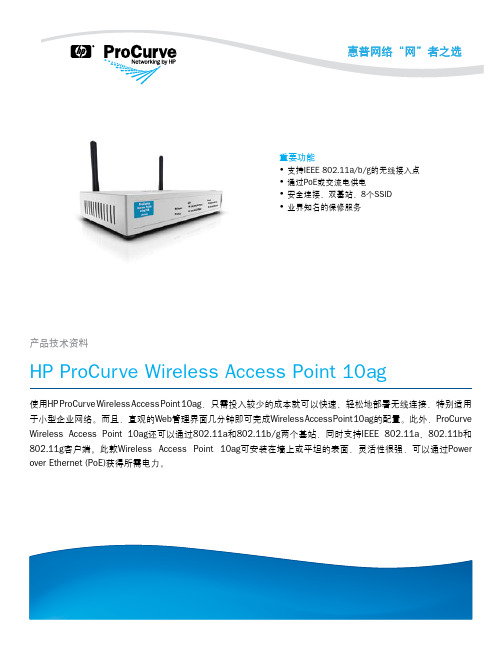
功能和优势业界知名的保修服务移动性• 互操作性:Wi-Fi联盟认证包括IEEE 802.11a、802.11b、802.11gWi-Fi和WPA2,可确保多厂商产品之间的互操作性连接性• 同时支持IEEE 802.11a和IEEE 802.11g双基站操作:支持64个无线客户端,向后兼容IEEE 802.11b无线设备安全性• 可选择Wi-Fi Protected Access 2 (WPA2)或WPA:允许访问网络前验证用户身份,以阻止未授权的无线接入;可靠的高级加密标准(AES)或临时密钥完整性协议(TKIP)加密可确保无线流量的数据完整性• 可支持8个SSID (每基站4个):可使用多种身份验证和加密设置,以充分发挥客户端的更多优势• I EEE 802.1X:提供基于端口的用户身份验证,支持可扩展身份验证协议(EAP) MD-5、TLS、TTLS和PEAP,并可选择AES、TKIP和静态或动态WEP加密,进而保护已通过身份验证的客户端与接入点之间的无线流量• 基于RADIUS的MAC身份验证:通过一台RADIUS服务器,根据客户端的MAC地址对无线客户端进行身份验证;该方法适用于具有较小用户界面或无用户界面的客户端• MAC地址封锁:避免已配置的特定MAC地址连接到网络• 管理密码:可阻止对Web浏览器界面的非授权访问可管理性• 直观的Web界面:利用简单易用的Web浏览器界面,简化接入点的配置、监控和管理流程• 与HP P roCurve M anager集成:通过可从网上免费下载的ProCurveManager进行发现和映射易用性• 全面的LED显示屏:可以一目了然地查看状态、活动、速度和基站运行情况灵活性• 灵活的电源选择(标准交流电或IEEE 802.3af PoE):能够满足不同地点的安装需求,可根据接入点的部署位置安装。
如要使用PoE选项,接入点需连接到PoE交换机或PoE插头。
HP ProCurve Wireless Access Point420单频接入点 说明书
ProCurve Wireless Access Point 420ProCurve Wireless Access Point 420是一个全特性IEEE 802.11g单频接入点,最适于部署大、中型无线局域网。
ProCurve Access Point 420提供最新的基于标准的安全性—包括支持IEEE 802.11i、WPA2和WPA以及多SSID、接入点(恶意接入点)和无线特定网络检测,其丰富的选择和较高的灵活性可确保在不影响网络安全的前提下,满足无线接入网络服务的需要。
ProCurve Wireless Access Point 420 NA ProCurve Wireless Access Point 420 WW特性与优点安全性-在不影响网络安全性的前提下,将无线网络接入拓展至移动用户•可选择IEEE 802.11i、Wi-Fi Protected Access2 (WPA2)或WPA:在允许访问网络前,通过对用户进行验证来阻止未经授权的无线接入;可靠的高级加密标准(AES)或临时密钥完整性协议(TKIP)加密可保证无线通信的数据完整性•IEEE 802.1X:提供基于端口的用户验证,支持可扩展验证协议(EAP) MD-5、TLS、TTLS和PEAP,并可选择AES、TKIP和静态或动态WEP加密,从而保护已验证客户端与接入点之间的无线通信•多达8个SSID,每个SSID均具有独立的VLAN、安全机制和身份验证:允许网络管理员根据用户验证及无线用户与接入点之间的信任安全级,控制用户对网络资源的访问。
例如,标记为“GUEST”的SSID不需要此SSID用户的验证或安全性。
“GUEST”SSID上的所有流量都被置于限制访问互联网接入等特定服务的VLAN上。
对于员工访问则配置另外一个SSID。
“EMPLOYEE”SSID需要使用带AES加密的IEEE 802.11i进行网络验证,以保护无线数据的安全。
WA-2200 802.11ac 2x2 Wave 2 无线接入点用户指南说明书
WA-2200Wireless Access Point User GuideContentsIntroduction3 System requirements3 Hardware installation3 Default settings and credentials3 First-time login3 Configure4 Overview6 Connections78 Backup/Restore9 Logs10 Advanced11 Device Settings11 LAN Settings11 Wireless Settings11 Access Control14 Firmware14 BakPak Lite16 BakPak Lite16 Reset to factory default settings18 Reset using the interface18 Reset using the physical RESET button18IntroductionAs the central component of your wireless network,the WA-2200802.11ac2x2Wave2 Access Point provides you with high-speed,high-range wireless8012.11ac networking.The AP broadcasts on both the5GHz and2.4GHz bands so that select devices can choose their preferred source of wireless connectivity,improving the overall stability,reliability,and performance of the wireless network.l For product regulatory information,see ctrl4.co/reg.l For product patent information,see ctrl4.co/patents.System requirementsMinimum system requirements:l PoE switch or injector,or an AC power adapter(not included).l A computer with an Ethernet port(for first AP setup).Hardware installationFor hardware installation and first-time startup instructions,see the Quick Start Guide found in the box.Default settings and credentialsl IP address:IP will be automatically assigned by router if a DHCP server is detected or,if no DHCP server is detected,the default IP address will be automatically set to192.168.1.21.l Username/Password(default):admin/passwordl SSIDs(default):Pakedge_Main(5GHz)and Pakedge_Alt(2.4GHz) Security/password:WPA2-PSK/pakedgewirelessl Guest SSIDs(default):PakedgeGuest2.4and PakedgeGuest5,security/password: WPA2/pakedgeguestl Transmit power for US and International models(WA-2200and WA-2200-C,WA-2200-1and WA-2200-C-1)18dBm for5GHz and13dBm for2.4GHzFirst-time loginThe first time you log in,you are brought to the Configure tab.Here you can change your username and password(strongly recommended),specify the device’s network name and physical location,set the Country Code,and create or hide wireless networks.For BakPak Lite setup instructions,see the WA-2200Quick Start Guide.ConfigureThe Configure tab allows you to change the most common AP settings in one screen.This is the default tab that displays after login.l Username and Password:The first time you log in,you should change these from the defaults(“admin”and“password”)to new credentials.l Friendly Device Name:Give the AP a descriptive name to identify it on its web interface screen and in BakPak.l Device Location:Describe the physical location of the AP here.l Device Note:Add any other notes here,such as date of installation and the technician name.l Time Zone:Select the time zone used for the AP’s event logs.l Country Code:Select the country where the AP is installed.l LAN Settings:l IP Network Settings:Select the method used for assigning IP addresses(DHCP or Static).l IP Address:For a static IP network,enter the AP’s IP address here.For a DHCP network,this field is read-only.l Subnet Mask:For a static IP network,enter the AP’s subnet mask here.For a DHCP network,this field is read-only.l Gateway:For a static IP network,enter the AP’s Gateway address here.For a DHCP network,this field is read-only.l DNS Settings:l DNS Server n(server’s IP address):For a static IP network,enter up to two DNS server IP addresses here.For a DHCP network,these fields are read-only.l5GHz Networks and2.4GHz Networks,and guest networks:Enter an SSID(wireless network name),the authentication type to use,the WiFi password,and the VLAN this wireless network is associated with.To view the password that’s entered,click the eye icon.Select Hide to not broadcast the wireless network’s SSID.l5GHz Guest Network and2.4GHz Guest Network:Enter an SSID(wireless network name),the authentication type to use,and the WiFi password.To view the password that’s entered,click the eye icon.Select Hide to not broadcast the wireless network’s SSID.OverviewThe Overview tab gives you a quick view of the AP’s status and critical settings.l Notifications:System notifications display at the very top of the tab.This example showsa firmware update is available.l Name:The device name(assigned in the Configure tab)appears here.l IP address and MAC address:The device’s assigned IP address and unique MAC address is shown here.l Update Firmware:Click to open the Update Firmware screen(also accessible under the Advanced tab).The screen also displays the firmware’s release notes.l Restart device:Click to restart(power cycle)the AP.It happens immediately,with no confirmation dialog.l Network information:Displays the number of wireless network SSIDs and the number of channels used by each.l Services:Displays the status of current services and settings and indicates with an icon whether the service or setting is optimally configured.ConnectionsThe Connections tab displays a list of connected wireless devices.Click any column head to sort the list by that field.Available fields are: l Hostnamel IP Addressl MAC Addressl Device OSl Connected Tol Strengthl Bandl Durationl TX/RXBackup/RestoreThe Backup/Restore tab allows you to save a configuration(backup)and restore the configuration file.l Save Configuration:Click to save a file that contains all of this AP’s settings.l Choose File:Click to select a saved configuration backup file to use for restoring settings.l Restore:Click to restore AP settings using the selected configuration backup file.LogsThe Logs tab displays a record of system events effected by the AP.The events are categorized and sortable by severity,timestamp,and details.l Enable Remote Syslog to save the logs on another network.You’ll also need to specify the remote Syslog server IP address and port.l Download Detailed Logs:Click to download more verbose descriptions of the logged events.AdvancedDevice SettingsClick this tile to configure LED settings,change the hostname or factory defaults,or to access diagnostic tools.l LEDs:Select to enable(or deselect to disable)the AP’s LEDs.l Hostname:Enter the hostname here.l Factory Default:Click to restore factory default settings.l Diagnostic Toolsl Ping:Select to ping a device at the indicated address.l Traceroute:Select to run a traceroute to the indicated address.LAN SettingsClick this tile to configure the advanced LAN port settings,such as management VLAN and STP.l Management VLAN:Click this toggle to enable the management VLAN.l VLAN ID:Enter the VLAN ID the AP is associated with.l Spanning Tree Protocol:Click this toggle to enable spanning tree protocol,then select Priority to change the priority from its default(32768).The lower the priority,the more likely the switch is to become the root bridge.(STP is changed in increments of4,096.) Wireless SettingsClick this tile to configure advanced WiFi radio settings such as channel,power,RF scan,and roaming features.l Wireless Settingsl Band Steering:Band steering steers5GHz-capable clients to that frequency.By enabling this function,the2.4GHz SSID and settings will be copied to the5GHzband.l RF Scan:Click to perform an automatic site survey of RF signals.The AP will scan the channels for connected devices and will then display them in a table.l5GHz and2.4GHz Radio Settingsl Enable:Click this toggle to enable this WiFi radio band.l Operation Mode:Both the5and the2.4GHz bands have the following operating modes:l Access Point:Standard mode of operation.Allows a wireless connection to the LAN.l WDS Root:The AP with this mode set will be the“root”device that APs configured with WDS Repeater and WDS Bridge will connect to.l WDS Bridge:This mode allows the AP to connect to a WDS Root Access Point.This mode takes in the SSID broadcasted by the WDS Root Access Point andturns it into Ethernet connectivity for client devices.l WDS Repeater:This mode allows the AP to connect to a WDS Root Access Point.This setting will take the SSID broadcasted by the WDS Root Access Pointand rebroadcast it to end-user devices.l Additional WDS Bridge and WDS Repeater settings:l WDS Root Access Point BSSIDl WDS Root Access Point SSIDl Wireless Mode:Choose the setting that corresponds to the type of wireless clients connected to your network.If you aren’t sure which type of clients will access thewireless networks,we recommend you keep the default settings.l Channel Width:Select the channel width for the selected channel to use.By default, it’s set to HT80MHz(when using5GHz)and HT20MHz(when using2.4GHz).Selecting40 MHz on the2.4 GHz band is possible,but not recommended,because itwill also increase the risk of impacting wireless performance.We recommend keepingthe2.4 GHz radio set to20 MHz and using only channel1,6,or11,because they are the only three non-overlapping channels.l Channel:Using the default setting(Auto),the AP automatically selects the channel with best performance for the wireless network.To select a channel manually,clickthe drop-down list and select a channel.The channel options available depend on the Country Code selected.l Transmit Power Level:The power depends on the distance of the devices in your wireless network.You can use this feature to increase or decrease the coverage area;however,we do not recommend changing this setting unless a professional sitesurvey is conducted.Contact your network administrator for help.l Auto:This setting adjusts the power of the AP based on the distance to the furthest client device.l For US model s(WA-2200and WA-2200-C):11dBm(13mW)–25dBm(316mW):These are static power settings.The AP willbroadcast at the selected power level.l For international model s(WA-2200-1and WA-2200-C-1):Transmit Power Level for International version depends on the Country Code selected(see page3).l Multicast Handling:Enable the Convert to Multicast toggle to enhance the video/audio quality when streaming multicast content to multiple devices over WiFi.When enabled,all the multicast traffic is converted to unicast,which increases thedelivery speed to individual devices.This feature is not recommended if the multicast group exceeds10devices.l Roamingl Fast BSS transition(802.11r):IEEE802.11r standard for fast roaming reduces the authentication time when clients roam from one AP to the other.This featureis beneficial for video streaming and voice application.l Client Reject RSSI:Helps with“sticky”clients that don’t reliably roam to the closest AP.By enabling this feature,the AP continuously monitors the station’sreceived signal and will de-authenticate the client when the RSSI falls below theuser-defined Client Reject RSSI Value threshold.This setting can be configuredindependently on5GHz and2.4GHz radios.l Guest Network Client IP Assignmentl DHCP:Select Internal or External.l Starting IP Address:This is the beginning of the DHCP range used on the guest network.If you have multiple APs,you can give them the same DHCP range because the guest network of each AP will be independent of each other.l Ending IP Address:This is the last IP address available on the DHCP range.l Subnet Mask:Select the class of the guest network.255.255.255.0is the standard setting and is selected by default.l GW IP Address:Enter the Gateway IP addressl DNS server IP address:The DNS Server IP can be set to an external DNS or to the router’s IP address if the router provides a DNS server.Access ControlClick this tile to set up access control for connected clients.To add a client for access control,click Add,then select the client and click Apply.The client and its identifying information are added to the Access Control list.Click any column head to sort the list by that field.Available fields are:l Hostnamel IP Addressl MAC Addressl RemoveFirmwareClick this tile to access cloud and local firmware upgrades.If your firmware is up to date,this screen shows your current firmware version and provides a link for that firmware’s release notes.If a firmware update is available,this screen also shows the update version and the update’s release notes.Click Upgrade to update the firmware from the cloud.BakPak LiteBakPak Lite is designed to provide remote cloud monitoring and configuration to the ing BakPak,you can remotely monitor and configure your customer’s AP without requiring a truck roll or a VPN session to the customer’s network.In just a few clicks,register your AP with your new or existing BakPak account.Registration is a two-step process where you register the Management Agent in BakPak,and then you link the management agent to an existing site or create a new site.BakPak LiteThe AP has BakPak Lite built in,which means it can remotely monitor other WE Series APs via BakPak.After the AP has been enrolled in BakPak,you can access it from anywhere in the world by using the BakPak app or the web interface at .If you see this message bar at the top of your access point’s web interface,the AP is not yet enrolled in BakPak.To enroll the AP in BakPak:1.On the message bar,click Click here to enroll.You are automatically redirected to.2.Log in with your BakPak credentials or create a new admin account.When you arelogged in,the serial number and MAC address will be automatically populated on yourBakPak account.To log in and view a site using the web interface:1.In a web browser,log in to .2.Under Sites,click Manage.A list of BakPak and BakPak Lite sites opens.3.Click the site you want to access,then click the BakPak Lite device that you want tomanage.The site’s management window expands,providing the following information:l Device information:Identifies all information about the device,including the serial number and firmware version,and has ability to reboot the wireless router remotely.l SSID configuration:Configure/edit wireless information for the primary SSID and guest networks.l Network Settings:Allows control of network settings such as DHCP,Spanning Tree Protocol,and Management VLAN.l Advanced Settings:Remotely configure the AP’s advanced settings(set the Country Code and Time Zone and enable bandsteering)and control5GHz and2.4GHz radio settings(Channel,Channel Width,Wireless Mode,Operation Mode,Transmit Power Level,Fast BSS Transition,and Client Reject RSSI).l Connected Clients:View information on connected clients,such as the SSID, Device OS,Hostname,Signal Strength,MAC Address,and IP Address.l Events:Displays network analytics,including a log of user events,for network troubleshooting.l Firmware:Applies firmware updates to the device.l Configuration:View the configuration files available on the ing the buttons, Apply a configuration file to the AP or delete the configuration files you are no longer using.Reset to factory default settingsWhile setting up or troubleshooting,you may need to reboot the AP or restore it to its factory default settings.Reset using the interfaceTo only restart the AP,maintaining all settings:1.In the Overview or Connections tab,click Restart Device.The AP restarts.To reset to factory default settings,deleting all user settings:1.Go to the Advanced tab and click Device Settings.2.Click Factory Default,then click Yes.Reset using the physical RESET buttonYour AP has a recessed RESET button accessible through a pinhole next to the Ethernet port underneath the AP.To only reboot the AP,maintaining all settings:1.While power is connected,insert a narrow,pointed object(such as a straightened paperclip)into the hole.2.Press and release the button.To reset to factory default settings,deleting all user settings:1.While power is connected,insert a narrow,pointed object(such as a straightened paperclip)into the hole.2.Press and hold the button for at least ten seconds,then release it.Copyright ©2020,Wirepath Home Systems,LLC.All rights reserved.Control4and Snap AV and theirrespective logos are registered trademarks or trademarks of Wirepath Home Systems,LLC,dba “Control4”and/or dba “SnapAV”in the United States and/or other countries.4Store,4Sight,Control4My Home,Snap AV,Araknis,Autonomic,BakPak,Binary,Dragonfly,Episode,Luma,Mockupancy,Nearus,NEEO,OvrC,Pakedge,Sense,Strong,SunbriteTV,Triad,Visualant,WattBox,and Wirepath are also registeredtrademarks or trademarks of Wirepath Home Systems,LLC.Other names and brands may be claimed as the property of their respective owners.All specifications subject to change without notice.200-00576-E MS2020-09-2211734S Election RoadDraper,UT 84020。
星网锐捷 无线ADSL 路由器 说明书
“星网在线” 无线ADSL路由器指导书目 录ADSL产品保修条款 (4)第一章产品介绍 (6)1.1产品介绍: (6)1.2产品特性说明: (6)1.3技术规格说明: (6)1.3.1 WAN(ADSL)口技术规格: (6)1.3.2 LAN口技术规格: (7)1.3.3 WLAN口技术规格: (7)1.4使用环境说明: (7)第二章硬件安装指南 (8)2.1产品接口和指示灯面板说明: (8)2.1.1 接口使用说明 (8)2.1.2 指示灯说明: (8)2.1.3 分离器接口使用说明 (8)2.2硬件安装 (8)2.2.1 包装检查: (8)2.2.2 安装连接图 (9)第三章软件配置指南 (10)3.1W EB登录到管理页面 (10)3.2W EB界面构成介绍 (11)3.3常用功能模块应用配置介绍 (11)3.3.1新建或修改一个ADSL连接 (11)3.3.2 无线模块(AP)参数与安全设置 (11)3.3.3 配置无线接口的mac过滤功能: (13)3.3.4 保存ADSL 设置 (14)3.3.5修改ADSL 局域网口IP配置: (14)3.3.6 配置DHCP服务器 (15)3.3.7 修改用户登录密码 (16)第四章典型应用方案介绍 (17)4.1动态IP应用方案->配置PPP拨号上网 (17)4.2静态IP应用方案->配置桥协议方式上网 (18)第五章无线网卡客户端的设置操作举例 (20)附:常见问题解答 (22)1、我曾经修改过无线ADSL路由器的网口IP,但忘记了,怎么办? (22)2、忘记了W EB配置的用户登录口令,怎么办? (22)3、如果ADSL无法拨号上网该怎么办? (22)4、无线网络不通,怎么办? (22)5、打电话时会使上网掉线,怎么办? (22)版权声明福建星网锐捷通讯有限公司2004版权所有,保留一切权利。
非经本公司书面许可,任何单位和个人不得擅自摘抄、复制本书的部分或全部,并不得以任何形式传播。
腾达无线路由设置使用说明书
版 权 申 明是深圳市吉祥腾达科技有限公司注册商标。
文中提及到的其它商标或商品名称均是他们所属公司的商标或注册商标。
本产品的所有部分,包括配件和软件,其版权属深圳市吉祥腾达科技有限公司所有,在未经过深圳市吉祥腾达科技有限公司许可的情况下,不得任意拷贝、抄袭、仿制或翻译成其它语言。
本手册中的所有图片和产品规格参数仅供参考,随着软件或硬件的升级会略有差异,如有变更,恕不另行通知,如需了解更多产品信息,请浏览我们的网站:目录第1章产品简介 (4)1.1包装清单 (4)1.2面板指示灯及接口说明 (4)第2章产品安装 (6)第3章如何设置上网 (7)3.1正确设置您的计算机网络配置 (7)3.2登录路由器 (12)3.3快速上网 (12)3.4快速加密 (13)第4章高级设置 (14)4.1系统状态 (14)4.2WAN设置 (15)4.3LAN口设置 (18)4.4DNS设置 (19)4.5WAN介质类型 (20)4.6带宽控制 (21)4.7流量统计 (23)第5章无线设置 (24)5.1无线基本设置 (24)5.2无线安全设置 (28)5.3无线访问控制 (29)5.4连接状态 (31)第6章 DHCP服务器 (32)6.1DHCP服务设置 (32)6.2DHCP客户列表 (32)第7章虚拟服务器 (34)7.1端口段映射 (34)7.2DMZ主机 (35)7.3UPNP设置 (36)第8章安全设置 (37)8.1客户端过滤 (37)8.2MAC地址过滤 (38)8.3URL过滤 (39)8.4远程WEB管理 (41)第9章路由设置 (42)9.1路由列表 (42)9.2静态路由 (42)第10章系统工具 (43)10.1时间设置 (43)10.2DDNS (43)10.3备份/恢复设置 (44)10.4恢复出厂设置 (45)10.5升级 (46)10.6重启路由器 (46)10.7修改密码 (46)10.8系统日志 (47)10.9退出登录 (47)附录一:常用无线名词解释 (48)附录二:产品特性 (50)附录三:常见问题解答 (51)附录四:清除无线配置文件 (53)附录五:产品有毒有害物质清单 (55)第1章产品简介感谢您购买腾达 11N无线宽带路由器(以下简称路由器)。
- 1、下载文档前请自行甄别文档内容的完整性,平台不提供额外的编辑、内容补充、找答案等附加服务。
- 2、"仅部分预览"的文档,不可在线预览部分如存在完整性等问题,可反馈申请退款(可完整预览的文档不适用该条件!)。
- 3、如文档侵犯您的权益,请联系客服反馈,我们会尽快为您处理(人工客服工作时间:9:00-18:30)。
© 2008 Cisco Systems, Inc. All rights reserved.
IUWNE v1.0—1-13
Directional (Cont.)
21 dBi Parabolic Dish
© 2008 Cisco Systems, Inc. All rights reserved.
© 2008 Cisco Systems, Inc. All rights reserved.
IUWNE v1.0—1-5
Antenna Types
© 2008 Cisco Systems, Inc. All rights reserved.
IUWNE v1.0—1-6
单向天线的应用
© 2008 Cisco Systems, Inc. All rights reserved.
IUWNE v1.0—1-7
Basic Omnidirectional
“Rubber Duck” 2.14 dBi Dipole
© 2008 Cisco Systems, Inc. All rights reserved.
IUWNE v1.0—1-8
Omnidirectionals
AIR ANT 1728, Ceiling Mount Omni 5.2 dBi
© 2008 Cisco Systems, Inc. All rights reserved.
IUWNE v1.0—1-9
AIR ANT 2506/24120
5.2 dBi Omni Mast Mount 12 dBi Omni Mast Mount
© 2008 Cisco Systems, Inc. All rights reserved.
IUWNE v1.0—1-16
放大器
衰减器
© 2008 Cisco Systems, Inc. All rights reserved.
IUWNE v1.0—1-17
Lightening Arrestors
Model to Insert Between Antenna and Cable
© 2008 Cisco Systems, Inc. All rights reserved.
“SMA” connector is used on “pig-tail” type cable assemblies.
户外是不能使用RJ45的。N头,大,固定,防水。
© 2008 Cisco Systems, Inc. All rights reserved. IUWNE v1.0—1-15
Attenuators and Amplifiers
An attenuator would be positioned in the same way as the amplifier, but it would not require a power supply.
© 2008 Cisco Systems, Inc. All rights reserved.
© 2008 Cisco Systems, Inc. All rights reserved.
IUWNE v1.0—1-3
Magnetic Field
90 degrees perpendicular to the electric field
© 2008 Cisco Systems, Inc. All rights reserved.
IUWNE v1.0—1-4
Diversity
Some wireless technologies use diversity to choose, on a per-client basis, which antenna to use to receive and which to answer. Antennae should be the same type and in the same area.
定向天线
8.5 dBi Patch, Wall Mount
© 2008 Cisco Systems, Inc. All rights reserved.
IUWNE v1.0—1-12
Directional
13.5 dBi Yagi Ude Butterfly Effect, Polarization
Describing Antennae
Wireless Fundamentals
© 2008 Cisco ms, Inc. All rights reserved.
IUWNE v1.0—1-1
Antenna Principles
The radiation pattern describes coverage shape. RF radiation pattern is described by Eplane (elevation chart) and H-plane (azimuth chart). Expressed in dB. Each antenna design produces different RF radiation patterns.
IUWNE v1.0—1-14
Cables and Connectors
“RP-TNC” connector is used on most Cisco APs.
“RP-SMA” connector is used on some Linksys products.
“N” connector is used on the 1500 Mesh and 1400 Bridge.
IUWNE v1.0—1-10
Special “Omnis”
Dual Patch Omnidirectional 5.2 dBi, Pillar Mount
© 2008 Cisco Systems, Inc. All rights reserved.
IUWNE v1.0—1-11
Directional Antennae
Splitters
分离器:信号分别发出,有衰减
Splitters divide the signal between two antennae, but considerably reduce range: a 21 dBi dish loses 4 dBi. Its range drops from 33 to 21 km on each side.
© 2008 Cisco Systems, Inc. All rights reserved.
IUWNE v1.0—1-2
Polarization
Polarization describes the orientation of the electric field.
It can be linear or circular. The magnetic field is on the right of the electric field. Wireless antennae can use any polarization, but consistency is required. Vertical polarization is common.
分离器
© 2008 Cisco Systems, Inc. All rights reserved.
IUWNE v1.0—1-20
Summary
Each antenna radiates in a unique way. Wireless uses vertical polarization. Some APs use diversity to offer better resistance to multipath issues. Antennae can be directional or omnidirectional. Omnidirectional antennae radiate 360 degrees in the H-plane. Directional antennae focus their beam more or less depending on models. Connectors are usually specific to a vendor. Attenuators and amplifiers can be added to change the power transmitted to the antenna. Lightening arrestors can mitigate the impact of surrounding lightening strikes on the AP and the network. Splitters can be used to split the signal of one AP to two antennae.
IUWNE v1.0—1-18
Lightening Arrestors (Cont.)
光电转换器
光电转换器
Fiber Interface
接地
接网桥
Ethernet Lightening Arrestor
光电转换器
IUWNE v1.0—1-19
© 2008 Cisco Systems, Inc. All rights reserved.
© 2008 Cisco Systems, Inc. All rights reserved.
IUWNE v1.0—1-21
© 2008 Cisco Systems, Inc. All rights reserved.
IUWNE v1.0—1-22