PSCAD Examples
PSCAD入门样例(强力推荐!!)
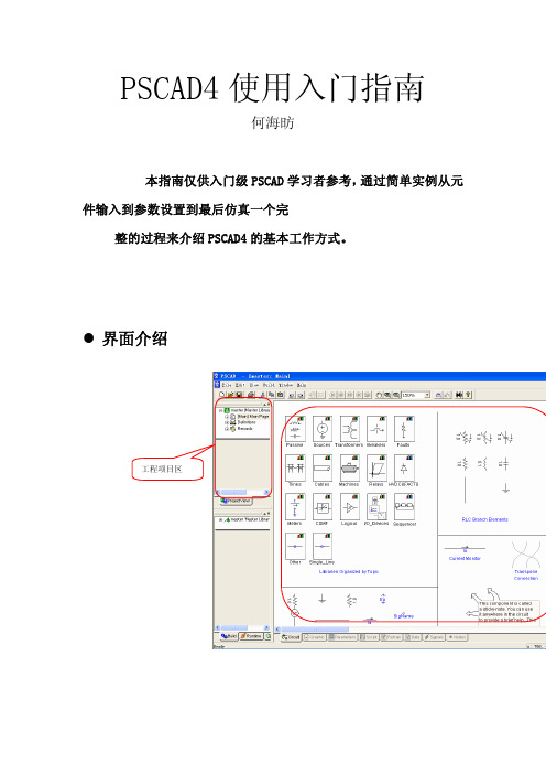
PSCAD4使用入门指南何海昉本指南仅供入门级PSCAD学习者参考,通过简单实例从元件输入到参数设置到最后仿真一个完整的过程来介绍PSCAD4的基本工作方式。
界面介绍通过一个简单实例来介绍PSCAD 的使用1.新建一个工程项目将得到一个名为noname 的工程项目,右击该项目将其另存为example2.为新项目添加电源元件,双击系统主库master[MasterLibrary] 的子项[Main] Main Page,元件库图标在编辑区域出现。
双击上图的Sources图标,进入到电源元件库中移动水平和垂直滚动条,选择单相RRL型交流电源,并将其复制(Ctrl+V),切换到example项目Main的编辑区域,单击右键粘贴(Ctrl+V),此电源就被加载到了用户定义的工程项目中3. 设定电源参数 双击编辑区域中的交流电源元件,进入电源属性设定对话框,这里电源的configuration属性页采用默认的值,即采用内部输入式交流RRL型,该电源一端接地,通常有些元件的参数比较多,可能需要点击下拉列表框来获得另外的属性页。
其它元件的参数设定也是一样通过双击进入属性编辑对话框来设置选择下拉列表中的Signal Parameters子项设定电压值、频率、初相等参数值,如果不明白参数所表示的实际意义,单击Help按钮进入帮助界面,帮助系统会给出要求用户填写的所有参数所代表的涵义4.绘制理想导线单击右边元件工具栏中的导线,移动到编辑区域中,再单击鼠标。
导线随即定位。
再次单击导线时,则选取了该导线,这时导线两端将出现绿色的小方形,点击并拖动小方形,可以调整导线在该方向上的长度。
如果选取了导线后,按键盘上的R键,则导线会顺时针方向旋转90O,当两条导线(或者是元件的管脚)的有一端相连时,会自动形成电气连接特性; 但如果两条导线(或者是元件的管脚)相交,但导线的所有末端都不相连, 则两条导线是相互绝缘的, 即实际上电气上是不相通的, 如果要使两导线交点成为电气节点,则置放一个Pin在交点上即可,后面采用了。
PSCAD应用实例(Part1)

30MVA Distribution Transformer 230kV/13.2kV, Delta/Wye-Gnd Ztx=7.65%
VSecA VSecB VSecC
A B C
A
COUPLED PI SECTION
A B
A B C
30 [MVA] #1 #2
A B C
y
230 [kV] 13.2 [kV]
1.25 1.00 0.75 0.50 0.25 0.00 -0.25 -0.50 -0.75 -1.00 -1.25 5.0 4.0 3.0 2.0 1.0 0.0 -1.0 -2.0 -3.0 -4.0 0.00 VbusA VbusB
Ferroresonance Case Study VbusC
Ea (kV) 1.50
FluxLinkage ()
d V dt
Imag
1.00 0.50
Current
0.00 -0.50 -1.00 -1.50
Ia (kA) 0.50
V .dt
Voltage
-4.00
Flux (Wb) 1.00 0.50 0.00
Flux
-0.50 -1.00 -1.50 -2.00 0.200 0.250 0.300 0.350 0.400 ... ... ...
0.003 0.0005 0.07 Eap
0.100 [MVA] .415 [kV] / 11 [kV]
AC System Studies
Utility Cap banks for voltage support
BRK
Manitoba HVDC
#1 #2
Research Centre
PSCAD简介.

1.00
0.50
dcCurrent Rec
0.00
定有功功率控制
-0.50 -1.00
VRec
VRec 1
2
3
Va Vb PLL theta Vc
Modulo *
360.0
e-s T
SEPh
Power (pu)
-1.50
1.20 1.00 0.80 0.60 0.40 0.20 0.00 -0.20 -0.40 -0.60
整流侧主电路
6 Rg62
5 Rg52
2 Rg22
500.0 [uF]
dcVltg
dcCurC1 Cable2 C2
15
5、PSCAD建模实例
Qvs c
Qvs c
dcVoltage Rec 160
dcVoltage Inv
Qrefr QerrR
Voltage (kV)
F
D
+ +
140
P
120
G
100
进行电力系统时域或频域计算仿真;
电力系统谐波分析及电力电子领域的仿真计算;
实现高压直流输电、FACTS控制器的设计。
4
2、工作环境(仿真流程)
PSCAD 解析工具
图形化 输入界面
PSC文件
含拓扑和 元件信息
计算结果
送回至 Pscad进 行显示
编译器等
EMTDC
转换为 Fortran 代码
转换工具
5
PSCAD(Power system computer Aided Design)作为EMTDC的 图形用户界面,完成所要研究系统网络图的构建、仿真运行和结果分析等 任务。
PSCAD详细使用教程(中文)

前言电力系统是非常复杂的。
其数学表达式的定义比航天飞行器及行星运动轨迹的定义更要错综复杂和具有挑战性。
比起计算机.家电和包括工业生产过程在内的一些大型复杂机器,电力系统是世界上最大的机器。
EMTDC是具有复杂电力电子、控制器及非线性网络建模能力的电网的模拟分析程序。
对于一个好的技术人员来说它是一个很好的工具。
当在PSCAD的图形用户界面下运行时,PSCAD/EMTDC结合成的强大功能,使复杂的部分电力系统可视化。
从20世纪70年代中期起,EMTDC就成了一种暂态模拟工具。
它的原始灵感来源于赫曼.多摩博士1969年4月发表于电力系统学报上的IEEE论文。
来自世界各地的用户需求促成它现在的发展。
20世纪70年代暂态仿真发生了巨大的变化。
早期版本的EMTDC在曼尼托巴水电站的IBM 打孔计算机上运行。
每天只有一两个问题可以被提交并运行,与今天取得的成就相比等编码和程序开发相当缓慢。
随着计算机的发展,功能强大的文件处理系统可被用在文本编辑等。
今天,功能强大的个人计算机已可以更深入细致的进行仿真,这是二十年前所不能想到的。
用户要求EMTDC仿真的效率和简便。
所以曼尼托巴高压直流输电研究所开发了PSCAD图形用户界面以方便EMTDC仿真的研究。
PSCAD/EMTDC在20世纪90年代最初创立并使用在unix工作站。
不久,作为电力系统和电力电子控制器的模拟器,它取得了极大的成功。
PSCAD 也成为了RTDS-时实数字仿真或混合数字仿真的图形用户界面。
Dennis Woodford博士于1976年在加拿大曼尼托巴水电局开发完成了EMTDC的初版,是一种世界各国广泛使用的电力系统仿真软件, PSCAD是其用户界面,PSCAD的开发成功,使得用户能更方便地使用EMTDC进行电力系统分析,使电力系统复杂部分可视化成为可能,而且软件可以作为实时数字仿真器的前置端。
可模拟任意大小的交直流系统。
操作环境为:UNIX OS, Windows95, 98, NT;Fortran 编辑器;浏览器和TCP/IP协议。
PSCAD例库

3.3 例子程序Program Files\PSCAD401\examples下的例子Tutorial,基本的PSCAD例子应用Readme_First,介绍PSCAD例子Active_filter,有源滤波C_Interface,C程序接口dc_machines,直流电机Hvdc,直流输电ind_machines,感应电机Lightning,过电压Matlab,PSCAD与MA TLAB接口PowerElectronics,电力电子PowerQuality,电能质量Relay_Cases,继电保护Rtp,实时回放Ssr,次同步谐振Statcom,高级SVC,静止无功发生器Svc,静止无功补偿器sync_machines,同步电机Transformers,变压器wind_farm,风力发电TUTORIAL FROJECTS(示例工程)PSCAD软件包安装时连同一个辅导性项目的目录,它包括许多简单的算例,这是为了说明PSCAD的各种特征。
这个目录在PSCAD安装目录下的examples\tutorial。
V oltage Divider(电压分压器):vdiv_1.psc一个简单的电压分压器,由电阻性电源和一个电阻构成。
解释如何组建电路、监视电压和电流、如何运行此仿真。
Fast Fourier Analysis(快速傅里叶分析):fft.psc显示了快速傅里叶分析元件的用途,并对信号进行实时快速傅里叶变换。
Simple AC System with a Transmission Line(简单的一个用传输线连接的交流系统):simpleac.psc、simpleac_sld1.psc、simpleac_sld2.psc简单的带传输线的交流系统。
介绍了PSCAD中变压器、传输线及子系统的概念。
Use of Control Arrays(控制组合的用途):pagearray.psc解释控制组合的用途以及怎样把电气节点输出到其它页面,这样即使你没有传输线,也可以在多个页面上完善电路。
PSCAD 4.2 说明文件

Welcome to PSCAD/EMTDC V4.2. Version 4.2.0 is available as a complete install only and can be installed alongside existing installations of PSCAD V3, V4.0.X and V4.1.XThere exist two separate installs, one for Professional/Educational and one forStudent/Evaluation Versions of PSCAD.Important NoteBlank Parameter Fields: When a component parameter field is undefined, earlier PSCAD compiler versions assumed a value of '0.0', a real number. This assumption is potentially risky since no real number was actually entered. By design in PSCAD V4.2, the compiler will no longer accept indeterminate input values and resolves to 'NaN' (see parameter viewing dialog). This produces a compiling error and will not run the case. The user model must have a valid default if the user does not enter anything. This may require previous version PSCAD model maintenance if defaults were neglected in the original design. More information on this item can be found by visiting /view_topic.php?id=466&forum_id=14 Windows XP Professional x64 Edition: If you want to run PSCAD 4.2.0 Professional or Educational on Windows XP Professional x64 Edition, you must configure PSCAD to get a license from a License Manager on another machine, or use a lockless trial license. The 32- bit Sentinel lock drivers supplied with the PSCAD and LM installers will install on XP 64, but will not run, so neither the License Manager nor PSCAD will be able to detect USB or parallel port locks.Correctly Uninstalling PSCAD 4.2.0: Use the Add/Remove Programs control panel to properly uninstall (remove) PSCAD 4.2.0. If you browse to the PSCAD CD and start Setup.exe and then select Remove, the uninstall process will remove all registry keys required by other installed versions of PSCAD V4. Should this happen, you need to repair the remaining installed versions of PSCAD V4.Known Issues1) The Hardware Key Rainbow USB driver version 7.71.9 does not properly support Hibernation/standby. The older version 5.39.6 Sentinel drivers properly detected the lock after waking up from hibernation & suspend modes, however there may be other driver conflicts with installed software. The new 7.71.9 drivers do not detect the lock after waking up from hibernation & suspend modes unless you unplug & replug in the lock. Sentinel says that this issue will be fixed in their next driver release due late Nov. 2005. At that time we will test the new drivers, and then deploy a patch through our support website.2) If you have two UMEC transformer instances in one case, where the first instance the saturation is disabled, and the second transformer saturation is enabled, the saturation parameters will affect the first UMEC component. The quick workaround is to disable the saturation of both transformers, or enable the saturation of both transformers. This will be fixed with the next maintenance release.PSCAD ImprovementsIn this section we have compiled a collection of brief overviews of individual changes to the architecture of PSCAD. The following items are not listed in any particular order, but provide some detail as to the nature of the change and how it may impact current users.Unit Conversion System:Unit conversion has been a high demand item for development in recent months. A new system has been integrated to perform automatic unit conversion. This function is a table based conversion utility build into the data manipulation code for the components. It operates as a separate object design to accept input as a source unit and convert to a defined target unit. It is important to note that there are 3 basic types of units conversion identified. They are:1) Direct proportional conversion (i.e. metre >> feet)2) Translational conversion (i.e. Celsius >> Fahrenheit)3) Domain inverse relationship (i.e. sec >> Hz)The unit conversion system implements the first form of conversion only. Proportional conversion has a common intercept point through zero and thus does not require the input value to provide a conversion ratio. In addition the conversion is capable of handling multiple terms as long as both the count and operator sequence match. An example of this is the conversion of [ohm/m*s] to [kohms/ft*s] where both the source and target units specification contain the same number of terms (3) and the same operator sequence (/*).Scaling factors prefixes are included in engineering factors of 103 each from pico(-12) to giga(+12). Scaling factors can not be combined in accordance to SI standards and are limited to 10e±12.Operator precedence is always left to right. Precedence control symbols '(' and ')' are not supported. Power terms are support with a “^” symbol, i.e. kg/m^3 w ould be kilograms per cubic meter.Literal terms are supported in a limited fashion. This allows for units to be specified as [1/s] for example, or even [3.14/s]. Literals can not contain a sign or any exponential as this is ambiguous with operators.If a conversion cannot be performed the system will return an indeterminate factor represented by #NaN which is then handled by the error messaging system. If the source equals the target the behaviour is unity (of course). If either unit is not specified then the default behaviour is unity (1.0). This behaviour is irregardless of an existing unit having literals or not.It is also possible to successfully convert units that are represented by common alias terms if they are provided in the database. Typical examples of this are [Hz] as an alias for [rev/s] and [rpm] as an alias for [rev/min]. Support for aliasing extends to single term unit specifications only. Multipliers are legal, so the term [kHz] will correctly convert to the compound term [krev/s]. This is possible since the multiplier is handled separately from the base unit.To support the units conversion object a new XML data file (units.dat) is included. This file must be placed in the home directory.It is important to note that this system was developed using the National Institute of Standards and Technology as a reference on SI. The implementation is partial and is intended for use in electromechanical systems. The reference can be found at:SI Standards Reference: <>Phasor Meter Devices:A new device have been add to the latest build of PSCAD to support complex pairs of Magnitude and Phase Angle created by the FFT component and others. The device displays instantaneous vectors (magnitude and angle) from the origin in the form of a thick line. If the magnitude exceeds 1 pu of the display an arrow is attached to the line to indicate it is out of scale. The display device will show either a single phasor or up to six phasors in an adjustable gauge display. Numerical values for the magnitude and phase angle are given at the footer panel of the device. The input can be toggles to accept values in either radians or degrees.Navigation History Bar:Users no longer need to try and retrace their steps by memory alone. A new Navigation Bar has been added to PSCAD that automatically tracks navigation within a project space.By design the style of navigation is using the same methodology that is commonly found in the Windows Explorer. As you move from one module definition to another, the history list is appended with each movement. This list is split at the current navigation point, filling the drop list next to the 'Forward' / 'Backward' buttons. User can move incrementally or by selecting a location directly.This system has significant benefit for large control system architectures where levels of detail may be nested several modules down from the top. Navigation through these complex cases is much simpler with a history control.Global Substitutions:Substitutions are well defined for definitions and widely used. These operate using input data as a source, while using the definition to define the actions. This means that all components of a certain type will process substitutions in the same way. If substitutions are required on a per instance basis, then this process cannot be used. Early implementations of and instance based substitution was called a global constant and allowed the user to enter a defined text string. This was then inserted as a value into an input field of a user component, but was limited for many other actions.This mechanism has been reworked and the concept of a global constant has been replaced. The big difference with the new approach is the process is completely general and does not require that a defined substitution be a numerical type. This allows for raw text substitutions combing both pre-fix and post-fix patterns. The syntax is the same as used for definitions as follows:$(<key>)There is no context key since the context is always that of the project. This text will be substituted at any point where a user component accesses its raw data. The raw data will be pre-processed with the substitution before it is returned for use. This allows the substitutionto act exactly as if the user entered that data into the parameter field. There is a small computation overhead to achieve this flexibility.Note: V4.1 implementation of Global Constants will no longer function and occurrences will need to be replaced with the above syntax. This was necessary since the constants were devoid of formal syntax, creating difficulties in resolution.Automatic Computations:Parameters are constants that are initialized in input fields. Computations are constants that are calculated from those parameters and/or other computations. Originally the computations were processes at the time a circuit module was compiled. This meant that none of the computed constants were available when a component is placed on the canvas. Changes have been made to the way in which a user component handles its computations. They are now processed in the layout procedure of the user component prior to the evaluation of the graphic flags and dynamic text in the component. In this sense they are automatically computed with the component and always remain available and up to date.More importantly, computations are now available for both graphic substitution and visibility expressions allowing the user to place a computed value on the display. This value will be undated whenever the component is placed on the canvas. Computations can also be created anonymously (no name identity attached) and used in the component. The anonymous expression substitution syntax:${<expression>}This syntax, although perfectly valid, is no longer required to perform dynamic computation text for graphics since the expression can be defined by a computation and substituted into the display like any other parameter.Extended Substitution Syntax:In an effort to standardize the substitution syntax, the parser has been extended to include a more formal way of handling substitution from other contexts. This comes from the need to pull information from more than just the component instance data. The standard syntax is:$(<context>:<key>)Where the substitution contains both a <context> and item <key> that are separated by a scope operator and delimited by round brackets. This syntax is intended to be standardized within the application to avoid multiple ways of performing substitutions. The name of the context allows the parser to insert information from objects outside of the scope of the component instance. These are:Defn, Project, Work, Session and System.When use for substitution within the context of the component instance, there is no need for a context and it is excluded along with the scope operator. In such cases the syntax is:$(<key>) or... $<key>This syntax is backwardly compatible with existing installations and the simple un-delimited form is the one that is use in most cases. (Both forms are now legal). The delimited versionhas special properties in that it can be used to format identifiers or other fields where there is an alphanumeric post-fix. This is a new capability. By design, if the character immediately following the '$' symbol is the same then that character is copied directly to the stream without processing. This allows for '$' insertions, for example, to insert a dollar-sign character, use $$. This is conventional syntax for substitution.Component Property Viewer:The previous release included a property viewer for component instances on the circuit. This has been greatly expanded to include a much greater level of detail and to aid in the debugging process of components and their models. In addition to the standard information provided by the definition and the parameter data, new fields have been added to include evaluated information for parameters and display of the expression for computations. This was a necessary addition as a result of the unit conversion system coming online. Failed evaluation will appear in the dialog as #NaN indicating an indeterminate state. This process is executed when the dialog is invoked and thus no compile step is required beforehand.This greatly aids the debugging process on a single instance to ensure that the evaluated data is valid prior to compiling. Parameters that are condition tested for enable/disable will appear with an asterisk (*) after the name if the condition returns false.Enhanced Message Balloon:Currently the errors and warning messages are displayed in a balloon component on the circuit canvas. Refinements to the balloon have extended it to display not just the current message but rather all messages pertaining to the component in question. Multiple messages are handled using small label components in a scrolling list. This way the user does not have to click on each message in the output window to see all the diagnostic information. In addition the balloon exists in a true window rather than a temporary component, giving it behaviour much like a toolbar.User Petition Support:A new dialog is in place to give licensed users a mechanism to send a petition to customer support directly from within the application using the Windows MAPI interface. Each petition includes the client ID, and application specific attributes to assist the support team, along with the associated question and/or comment. This system provides a convenient mechanism for users to relay bugs and suggestions to the support staff, and to respond to those concerns in a more organized fashion. This is part of the main help menu.Sequence Components ordering repaired:The solution is to design multiple sources into the signals on the netlist and reworking the signal sources so that it could accommodate the unusual behaviour of the sequence components. Once that was in place, some small changes to the circuit decomposition and ordering algorithm extended it to handle the signal changes. Since the decomposition algorithm is already designed to handle multiple sources (from different input signals), it is a natural extension to allow multiple sources for the same signal.Implicit Bus linking enabled:The bus component has new functionality that allows the name of the bus to act as an implied connection. Users can then split a large bus into smaller segments, and those segments are implicitly connected together. This is not the previous behaviour so is turnedoff by default. The user can turn it on in the project settings. In addition the colour of the bus is set using the base voltage.In general, electrical node labels are not connected and were not part of the planned behaviour. It has been known that they would in fact connect if named alike. This behaviour has been restricted to buses to encourage formalization of an implied electrical connection. This is less likely to be error prone.Idle time polling:To ensure fast response in the data communication between PSCAD and EMTDC, the simulation of smaller systems is continuously polled, providing maximum performance. On larger networks, the simulation can run significantly slower and it is not necessary to poll the simulation continuously. To free up processor cycles an allow other applications to run more smoothly, a switch allows this polling to only occur during periods when the application not busy, referred to as "idle time". If this option is set, larger networks will use this method instead, reducing the processor loading from PSCAD.Associations for commonly used programs:A new extended list box control has been added to the workspace dialog to manage the file associations. This give greatly extended file associations with file references. Its look and feel resembles the one that you can find in the dialog of the Visual Studio environment. This new list box allows in-place item editing, and a "browse" button near the edit field. Once set these associations are stored as user system properties in the registry.Window tabs auto-adjust for width:The previous tab window tabs had a fixed size. When the window is too small to fit all the tabs, they simply cropped at the right edge. This has not been a problem for the workspace until the recent addition of a transmission line view. New code has been implemented to improve the tab window and it now auto adjusts the tabs to fit the width (cropping text as necessary) if the width is not sufficient to show them all.Matrix Memory Optimization:Changes have been introduced to improve the memory efficiency of EMTDC simulations. Larger systems that contain many transmission lines naturally spilt the full matrix into smaller matrices called subsystems. The purpose of separating the network into to smaller matrices is to both save memory loading by avoiding large n*m allocations and to increase speed of inversions due to switching events in the simulation. However, systems with a large number of these transmission lines can break into subsystems with too fine a granularity resulting in an allocation of n*m*o which is actually larger than the original single matrix. Changes have been made to the matrix mapping algorithm to allow it to identify multiple un-switched networks within a module and pack them into a single subsystem. This is not a system wide approach but is simple and effective enough to provide a noticeable reduction in memory usage for these types of complex systems. If a module has no switched elements, its components will always be retained within the same subsystem.Tri-Segmented Wire Type:Based on the wire class recently integrated into the application, a new tri-segmented type has been developed to specifically handle situations where a pure orthogonal wire is not sufficient. The three segments are composed of two orthogonal elements are each end anda single diagonal element in the middle. Stretching and resizing these allow for a large number of potential shapes and combinations as in interconnect between two orthogonal elements and especially for interconnecting buses. It is current ly implemented in one fundamental base type for transmission lines and cables and is fundamental to future compatibility with flow diagrams under development.New Wire Class:A new wire class has been created to support advanced movement and manipulation. The new wires provide fundamental support for single and multi - segmented wire type, buses, and new 4 pointed diagonal types used to support the transmission lines. This new type provides new drawing constructs that allow for multi-rectangle (region) based components. The region concept then extends the capabilities of many components other than those based on wire.Drag & Drop Extensions:To speed up the creation an movement of curves on the design canvas, the capabilities have been extended to allow the user to drag curves from one graph to another or around the same graph to sort the order. In addition, copies of the curve can be created by holding down the <ctrl> key and dragging a new curve from the existing one.Transmission Line ImprovementsNew Line Constants Viewer:A new Line Constants Output data viewer is available. LCP detailed output files are composed of a variety of detailed data, which is written to column formatted, ASCII text files. As the detailed LCP output data are distributed with 14 text files, it also depends on whether the user has selected the FD (Phase) or the FD (Mode) model. LCP data viewer is a dialog with data listing area and a residential tool bar. There is also a drop list selection which provides the switching between the various output data files.Transmission Line/Cable tree view in PSCAD Workspace:A new TLines/Cables view is added to the workspace window. If the project has been compiled, the tree populates grouped tlines and cables under the project parent tree. Each line that has remote ends connection type should also have two child tree nodes to represent the sending and receiving ends.New Line Constants Program:The ability to increase the number of frequency solution steps between the specified start and end frequencies (frequency dependent (Phase) model only) has been added. This feature has been shown to improve curve fitting results in highly non-linear line segments. For normal lines, the default of 100 frequency steps is sufficient.Detailed output files are now output with unique names. Also, the respective calculated and curve fitted output files for surge impedance, attenuation constant and current transform quantities were merged together. Formatting was changed to simplify the process of plotting these output quantities in the pending detailed output plotting utility for v4.2.Eigenvalues and eigenvectors are now output to detailed output files '<linename>_eval.out' and '<linename>_evec.out'.The internal Newton-Raphson (NR) procedure for calculating eigenvalues/eigenvectors was modified to reduce the maximum number of iterations. Testing has shown a dramatic increase in solution speed in highly complex line segments (such as complex, multi-layer cables) without affecting the results. The log file has been improved to better indicate what is happening while the NR procedure is invoked. In the past, whenever the 5000 maximum iterations were hit, the routine would output the message 'Failure to Converge' -- sometimes many times over. Now, dynamic indication is provided to show how the NR procedure is searching for a frequency that provides a convergent solution.EMTDC and new ModelsThe following items have been improved in EMTDC.∙Intel Visual Fortran version 9 is now supported.∙ A new multimeter model has been added to the master library. This component allows simpler access to P, Q, V, v(t), i(t) and phase angle signals at one point.Previously several components were needed to collect the same information.∙ A permanent magnet motor model is now available. An example case under "examples" highlights this models usage.∙Many single input CSMF components now support array inputs to reduce the number of components required to draw the circuit. Also, interpolation is now fullyimplemented into the CSMF and Logic libraries.∙Machines and Sources may now be initialized by terminal conditions simplifying data input conversions from other programs (for example, a power flow).∙ A PT model has been added, and the 50/51 relay updated to allow simpler data input.∙Breaker and Fault models now have current chopping capability. The user can specify a certain limit where breaker will chop the current without waiting for a zerocrossing.∙Resetting capability is added to Differential, Real and Leadlag poles.∙The FFT and THD components are handle up to 255 harmonics.∙The hpfilter component is now branch based, as opposed to node based, to improve compatibility with PSCAD Single Line Diagram functionality.∙Checks are now added to verify whether changes to the project invalidates the snapshot.∙New components:- angle_resolver to limit the angle within the specified range,- polar_rec to convert quantities between polar and rectangular coordinates,- prod_array to get the product of all the elements in an array,- sum_array to get the sum of all the elements in an array. A- simpler fixed load component.Notable bug fixes∙ A bug in VDIFPL8 routine is fixed. This routine is used inside IEEEexciter/governor/turbine models.∙VARRLC now correctly models idL/dt and vdC/dt terms.∙ A bug in COMTRADE 99 format output is fixed.∙ A bug in frequency tracking option in FFT component is fixed.∙The nth order transfer function and nth order filter storage pointer bug has been fixed. License ManagerThere have been several enhancements to the License Manager.- improved licensing and additional diagnostic messages- License Manager now uses the Sentinel Drivers 7.71.9 to eliminate driver conflicts with PSS/E.- Improved Licence Manager support when the computer comes out of suspend or hibernation modes. PSCAD no longer will lose it’s license.- Previous versions of the Licence Manager service would often hang when the user would attempt to stop the service, necessitating a reboot. This issue has beenresolved.- Licence Manager only logs errors when they are first detected, not every 60 seconds reducing the size of the log files.- PSCAD will warn the user if any installed trial or temporary licences will expire within the next 2 weeks.Additional Notes:PSCAD V4.2 is fully compatible with PSCAD V3, and has significant improvements for the import of PSCAD V2 for Unix/Linux.In order to run PSCAD/EMTDC, a FORTRAN compiler is required. We currently support:- Intel Visual Fortran (9.0.018, or higher),- Compaq Visual Fortran V6.x,- Digital Visual F90 (V5.0),- as well as the Shareware GNU Fortran/C compilers (the GNU compilers are available for free download from our web site, ).Service and Support:For more information on updates/support, please visit our website and PSCAD Forum at . If you have any suggestions regarding this software, please send e-mail to the address below.For information on PSCAD/EMTDC courses, or custom model development, please contact:。
PSCAD例子的学习(对部分example的解释)
PSCAD例子的学习笔记、黄金分割法(在optimum_run )PSCAD Professional 一 [siBplex_siApIe: Iain]File Edit View Euild Windcw Help®晶髦遣© a 題從150%二心0 ▼ : 曰巴回阔翳鸚 ® ®® ® |iooon T| 菱卜氏仙A 二j-[J master (Master Library] 由崔]-1: [Main] Main Page [+.国 Definitfons -[J golden^ise [Golden S ecticn * Minirmce Integral Square E rror)&□ m^ter (Master Library)由轡-1: [Main] Main Page 田凰 D efiriitionsF miirirurLsId (A Simple Multiple Run Example)|圉 -1: [Main] Main Page1 —S 园 Definitions ___________________E 目 H MkeJee¥es_fiimp>e (HookeJsevei ,Simple Function Evaluation] 逹j -1: [Main] Main Page +]岡 Definitions=E3 $implex_mirih3rni (SIMPLEX - Minimije harmonics genefated) I 「對 *1: [Main] Main Page +卜虜 DefinitionsI-包 simplex_simplE (SIMPLEX' Simple Function Evaluation) 岸j -1: [Main] Main Page + 国 D efinitions种优化方法卜电]-1: [Main] Main Page 由.凰 DefinitionsVsriable X.word 可编辑.二、电能质量 (在PowerQuality 中)软件的英文说明:This applicatio n example is based on a case origi on ally created at the Man itoba HVDC Research Centre by Dr. M. Reformat, i n Man itoba. Can ada.This case illustrates the use of a STATCOM to provide active filtering for the ac side of a 6-pulse converter system. The Active filter is connected through a 20 kVA, Y-YXI[opt ±MU*_run] Opt I AUMISEcult cuit eorri compltran sformer to a 200 V, 50 Hz, 3-Phase bus, with a 6-pulse con verter loadREFERENCE:H. Fujita and H. Akagi,'A Practical Approach to Harmonic Compe nsati on in Power Systems - Series Connection of Passive and Active Filters', IEEE Trans, on In d.Applicati ons, vol.27, No.6, Nov/Dec 1991, pp. 1020-1025Revised by J.E. Nordstrom - September 2000软件的英文说明VOLTAGE SOURCE 200 V, 50.0 [HUJIX--25【ohm 一COtTl 亠Bus谐被源的员带控制系统的有源滤波Pl 门 3D -<piby19®ACTIVE FILTER'l| ------ (V)-vW^G PuliseBridgeAMGMActive Filter 5P STATCOM Based Device With Control SystemThis applicatio n example is based on a case origi on ally created at Man itoba Hydro, inMan itoba Can ada.The problem was that farm ani mals, duri ng win ter mon ths, were experie ncing a "tinglevoltage", due to suspected poor grounding on the local ground grid.Using PSCAD, the engineers were able to simulate the local system and determine that the grounding problem was at least partially related to ground rod resista nee. During the win termon ths, t he ground con ductivity is poor, result ing in a poor connection betwee n theground rods and earth.rod While this case is running, you can adjust the ground resistanee. Notice the cha nge in voltage across the cow!Revised by J.E. Nordstrom - July 2000三、继电保护 Case 1:-Two Thev inen Impeda nee sources conn ected via one 100km tran smissi on line.(双电源系统通过 100km 长度相连)-System voltage is 230kV settable via source equivale nts.(230kV )-Simulates two substati ons conn ected via one tran smissi on line. (仿真两个变电所之间的传输线路 )H R .FerdEr UinbdoiccdI3KWW budf & IMi'A_ITZbOmZb△*接地象Ciptwe Tap Rtflf tam C3TIT1 I EC Orn牛■SdaFMT fxk¥A f 3k>s_MVMlJril I iti Gnu^NMHCm tamer Urtidai □: <112QT<J^ Load-^w — 吋|*n<Vi^4r Fd iLtift-VW —B 厲Fn 口 InhrC——Wrf —SEIO [ctvi^;1^—-vW —b mtaag 1t^widihtadValAli Tlwirejid NcuM-Four fault positi ons for full fault con trol ahead and behi nd stati on relays. (设计了四个故障点)-Two breakers are in depe nden tly timed con trolled. (Default is closed). (两侧的断路器可以通过时间,默认是合上的)In depe ndent breaker pole tripp ing is possible.(可以实现分相操作)Ante" W ■Wfi・i・Hi・—m输电线路“■u v n-.-■=_ 8」1 T h r w 故障点故障点故障点故障点宇制子系—二52I.W信号供观察右價I系统察子系画图 斷路器操作. 馬四个量输岀 FT^pe Fault;fflControls注意拖动之前定义及O制面板,原是光屋制面板,原是光Adjust phase angle to obtain the correct power flow. Adjust voltage to obtain the matching VAR flow at each end.[工PREFAULT CONTROLS压线功个超 要使的的功皿不 重故卄再,过在理有30高ar持合即超最va 处伪先电^®,不功皿 此在,侧与路歪¥咼无10smission I-Indape i relays. ised)-Simula -Four fa Case 1: -Two Th.word 可编辑.吃0 RTP 尺氏皿lerNo. 1Tii^strii -_ ------------------ n Formal: RTP * O~~OComtrade 91 °」Corrrtrade 99*Digital InpuUFault录波器的控制开关Ray back Recordl&rsReconders0.15 0.5T& turn the Recorders on. tickon the switch. □h = R^coinder will r&comd datJi,Off = Recomder will N OT recordl datau You can, turn on oroiff eachuwwder hdi vdijally.■ ■ 」「 Thiedcioied^t)重合闸时刻BREAKER CONTROLS跳闸时刻控制开关MutbifMrclejirlig ifne ciidncicNf Hue 「rg ifitedlgd录波器,供分析用VIA VIS VIC 111A I1B I1C Analog InpulsVIA V20 V2C I2A I^BA?TStagEM ] Anailo g Inpuisv2 0 RTP 尺 emriJer No 2 File: stn2 'Formal: RTP ° O~OC o mtrad e 91QComtrads 99*DiQilal InpuU字量。
PSCAD模块库功能教程(包含与matlab接口)
11. Impulse Generator(脉冲发生器)
脉冲发生器用来确定线性控制系统的频率响应。其可以产生指定频率的脉冲序列。 在对控制系统进行分析之前,为了使得暂态响应逐渐变弱,需要使用一些脉冲通过控制 系统。当然频率可以置零,仅发送一个脉冲给控制系统,即可以观测到频率响应。 如果使用插值法,此组件在每生成一个脉冲的同时也生成了插值信息。对应于脉冲 的准确时间的插值时间非零,以保证脉冲无论何时都不会落在时间步长坐标上。这就有 效的祛除了组件对设备步长的依赖性,即使时间步长增加也能保持精度。
2. Differential Lag or Forgetting Function(微分延迟或遗忘函数)
微分延迟组件用作一阶高通滤波器,有时也叫做冲蚀函数、改变函数、或者遗忘函 数。输出可以随之置为用户指定的值。对此函数的解法如下,基于时间常数 T 的值。
Q t Q t t e
注意:从实数转换为整数是 NINT 操作(取最近的整数),若 1.4 就转为 1,若 1.6 就转
为 2。或者采用 INT 操作,恒向下取整,即 1.4 和 1.6 都转为 1。
6. Data Merge(数据合并到一个数组)
本组件最多可将 12 个标量合并到一个一维数组中(数据向量)。与本组件输入端 相联的所有信号的数据类型都转换为输出所选择的数据类型。整数型输入转为实数型, 以及实数型输入转为最近的整数型都采用 Fortran 的 NINT 功能。 将逻辑型输入转为实数 型或整数型数据无法自动完成。如果输入的数据类型不一致,则需要首先使用“Type Conversion”组件将它们转为所需的数据类型,然后再合并。 数据组件可按如下所示方法使用:
t T
X t X t t e
PSCAD电力网和EMT程序中的电磁暂态基础Fundamentals of EMT Part3
• Reactive power control is possible • “Lower’ rating for the converter – Cost • Allows the machine speed to be controlled as the wind speed varies
pu
pu
MW
MVAR
1.00 0.50 0.00 1.050
V r ms _pu Wpu
1.000
1.00 0.50 0.00
2.0
PG QG
0.0
-2.0 2.40
2.60
1.00 0.50 0.00 1.100
V r ms _pu Wpu
1.050 Pg
0.50 0.00
0.250
Qg
-0.200 2.40
TL WindTRQ
BUS 8
Wind Park
-3
Cp 0.28
Tm
Vw
Ws pd
Wm W4
+ +
D
F
Change wind speed fom 12 to 10.5 m/s
TIME
A doubly fed induction machine is popular in wind farms due to its flexible operation under variable wind conditions. PSCAD is used by wind farm developers and researches to design the complex control functions of the DFIG
PSCAD教程笔记实际操练
PSCAD 教程笔记实际操练
Getting Started - Tutorial 1
第一步:找模块
Ia
66 kV,60 Hz Source
Z+ = 3.9Ohms / 75.58 deg
Z0 = 14.95 Ohms / 80.46 deg Y-Y Transformer
7.5 MVA
Z = 6.14 %
Full load loss = 0.3%
No load loss = 0.5%
No load current 1 %#1
#
2
1e666 kV BUS
RL
RRL
图1:笔记上的图
图2 建立一个新的case
方法:随便给新的case起个名字,存在能找到的地方。
然后在Master library中找符合笔记上图的相关元件,采用复制、粘贴的方法,在新文件的[main]中放好位置。
相应的信号
第二步:定属性
见图1,所有元件都有相关的属性,要一一定好。
发电机定属性:双击打开后改属性。
改后的效果。
通过下拉菜单,找到输入阻抗的地方。
输入相应参数(在图1上有)
同理输入零序参数:
变压器定属性:双击打开后改属性。
最终效果图:
注意:上图中有Ia、E66为电流、电压表,是需要从界面右侧的工具栏中拖动过来的。
如果各元件之间未联接好,则编译会出错,要学会用窗口上方的“W”画线工具。
- 1、下载文档前请自行甄别文档内容的完整性,平台不提供额外的编辑、内容补充、找答案等附加服务。
- 2、"仅部分预览"的文档,不可在线预览部分如存在完整性等问题,可反馈申请退款(可完整预览的文档不适用该条件!)。
- 3、如文档侵犯您的权益,请联系客服反馈,我们会尽快为您处理(人工客服工作时间:9:00-18:30)。
PSCAD教程模型:PSCAD Tutorial Cases:
These cases can be found under the <PSCAD_Install_Directory>\Examples\Tutorial directory.
分压器模型:Voltage Divider
vdiv_1.psc A simple voltage divider circuit with a resistor and a resistive source. Demonstrates how to assemble a circuit, monitor voltage and current, and run the simulation.
在线FFT模型:Fast Fourier Analysis
fft.psc Shows the use of Fast Fourier analysis component
to perform online fft on signals.
带一条输电线的简单AC系统模型:Simple AC System with a Transmission Line simpleac.psc A Simple Ac system with transmission lines. Introduces transformers, transmission lines, and the concept of subsystems in PSCAD. simpleac_sld1.psc and simpleac_sld2.psc are two forms of single line representation of simpleac.psc.
控制数组的使用:Use of Control Arrays
pagearray.psc Demonstrates use of control arrays and how to export electrical nodes to other pages so that a circuit can be modeled on multiple pages even if you don抰have transmission lines.
滑块、开关、按钮和拨号盘的使用:Use of Slider, Switch, Button, and Dial
inputctrl.psc Shows the use of dynamic input devices: Slider, Switch, Push Button and the Dial.
多重运行(检测各种故障下的母线最大过电压):Multiple Run
multirun.psc A simple control system design example to demonstrate the use of multiple run features to determine worst case overvoltages. multirun_sld.psc is single line representation of the same case.
电压电流振荡的去除:Chatter removal
chatter.psc A simple case illustrating removal of chatter - numerical oscillation (every time step) in voltage or current which is caused by trapezoidal integration. Voltage chatter occurs whenever a disturbance is applied at a node to which only inductors are connected. Current
chatter occurs whenever a disturbance is applied at a location where capacitors are connected in a loop.
插值(改变触发角角度):Interpolation
interpolation.psc A simple case of GTO device using interpolation. Interpolation is an integral part of EMTDC which allows switching devices to switch at any instant of time instead of only on the regular time step grid. This allows the use of a larger time step without missing current zeroes or other switching instants.
PSCAD案例模型:PSCAD Example Cases:
These cases can be found under the <PSCAD_Installation_directory>\Examples directory.
轻型高压直流输电模型:hvdc\vsc2 - Voltage Source Converter Transmission Examples
大电网HVDC标准模型:hvdc\cigre - Cigre HVDC Benchmark Example
与Matlab接口案例:Matlab - Various Examples demonstrating the interface of PSCAD with Matlab.
静止无功发生器模型:Statcom - Statcom (Advanced SVC Facts Device) Examples
串并联有源滤波器模型:active_filters - Series and Shunt Active Filter Examples
雷电过电压模型:lightning - Steep Front Overvoltages Example
IEEE次同步谐振第一标准模型:ssr - IEEE SSR Benchmark Example
静止无功补偿器模型:svc - Static Var Compensator Examples
简单电力电子电路模型:PowerElectronics - Examples of simple power electronic circuits
电能质量模型:PowerQuality - Examples of applications related to power quality
实时回放系统模型:RTP - Demo cases for the Real Time Playback System
using the COMTRADE recorder component.
同步电机及原动机、励磁系统、PSS和轴系多质量块模型:sync_machines directory
This directory has many examples to illustrate the use of synchronous machines and its accessories such as governors, exciters, stabilizers, and multi-mass models.
异步电机模型:ind_machines directory
This directory has many examples to illustrate the use of induction machines and its accessories such as multi-mass models.
直流电机模型:dc_machines directory
This directory has many examples to illustrate the use of dc machines and its accessories such as multi-mass models.
变压器模型:transformers
Includes an example of connecting single phase transformers to form a Scott connection.
以上仅是例程中仅是……PSCAD42/examples/Readme_First.psc文件中所提到的,实际在examples文件夹下还有风电机模型(感应电机、同步电机、软启动)、固定负载模型等等。