Smart Link configure guide
Smart Link配置示例

双Smart Link组配置示例
SWB
GE2/0/1
Monitor Link组
GE2/0/1 GE2/0/2
SWA GE2/0/2
Monitor Link组
GE2/0/1 GE2/0/2
SWC
Smart Link组 1
GE2/0/1 SWD
HostA
Smart Link组 2
GE2/0/2
[SWD] smart-link group 2 [SWD-smlk-group2] protected-vlan reference-instance 1 [SWD-smlk-group2] flush enable control-vlan 20 [SWD-smlk-group2] port gigabitethernet 2/0/2 master [SWD-smlk-group2] port gigabitethernet 2/0/1 slave [SWD-smlk-group2] preemption mode role
单Smart Link组配置示例
SWB
GE2/0/1
Monitor Link组
GE2/0/1 GE2/0/2
SWA GE2/0/2
Monitor Link组
GE2/0/1 GE2/0/2
SWC
Smart Link组 1
GE2/0/1 SWD
HostA
GE2/0/2
[SWD] smart-link group 1 [SWD-smlk-group1] protected-vlan reference-instance 0 [SWD-smlk-group1] flush enable control-vlan 10 [SWD-smlk-group1] port gigabitethernet 2/0/1 master [SWD-smlk-group1] port gigabitethernet 2/0/2 slave
H3C配置手册-Smart Link和Monitor Link
Smart Link和Monitor Link Smart Link Monitor Link引入⏹Smart Link是一种针对双上行组网的解决方案,实现了高效可靠的链路冗余备份和故障后的快速收敛。
靠的链路冗余备份和故障后的快速收敛⏹Monitor Link是对Smart Link技术的有力补充。
Monitor Link用于监控上行链路,以达到让下行链路同步上行链路状态的目的,使Smart Link的备份作用更加完善。
⏹本章对这两种链路层高可靠性技术进行介绍。
课程目标⏹掌握Smart Link 的运行机制和配置学习完本课程,您应该能够:⏹掌握Monitor Link 的运行机制和配置S t Li k M it Li k ⏹掌握Smart Link 和Monitor Link 的典型组网目录⏹Smart Link简介⏹Monitor Link简介Monitor Link⏹Smart Link & Monitor Link典型组网⏹Smart Link & Monitor Link配置SWASWCSWB Smart Link 解决方案实现了主备链路的冗余SWDSmart Link 解决方案,实现了主备链路的冗余备份,具备快速收敛性能,收敛速度可达到亚秒级。
SWAVLAN10SWCSWB Smart Link 组Master Port Slave PortVLAN10SWD 上的二个端口组成了一个Smart Link SWDVLAN20上的二个端口组成了个Smart Link 组,端口分别为主端口和副端口,发送控制VLAN 和接收控制VLAN 为VLAN 10,保护VLAN 是VLAN 20。
Flush 报文Destination MAC Address =010F-E200-0004(6bytes)Source MAC Address (6bytes)...Control Type =0x01(1byte)Control Version =0x00(1byte)Control VLAN ID (2bytes)SWID (6bytes)Auth-mode (1byte)Password (16bytes)VLAN Bitmap (512bytes)当Smart Link 组发生链路切换时通过发送FCS (4bytes)p (y )Smart Link 组发生链路切换时,通过发送Flush 报文进行MAC 地址转发表项和ARP/ND 表项的刷新操作。
TP-Link Smart Switch 安装指南说明书
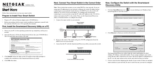
Follow these instructions to set up your smart switch. Prepare to Install Your Smart Switch•Prepare a PC with an Ethernet adapter and a CD ROM drive.•Before proceeding with the smart switch installation, familiarize yourself with the contents of the Resource CD, especially the manuals.First, Install the Smartwizard Discovery Utility on a PC 1.Power on your PC, let the operating system boot up completely, and log in asneeded.2.Insert the Resource CD for the Smart Switch Series into your CD-ROM drive.The CD main page shown below will load.3.Click Install. Follow the links on the CD and the setup utility prompts tocomplete the installation of the Smartwizard Discovery utility.4.Click OK when done. Next, Connect Your Smart Switch in the Correct OrderNote: These instructions assume you are using DHCP in your network. If you areusing static IP addressing in your network, configure the switch IP address beforeconnecting it to your network. In the absence of a DHCP server, the switch willdefault to 192.168.0.239 for its IP address. To configure the switch beforeconnecting it to your network, set up the PC with an IP address in the 192.168.0.xsubnet, and connect the PC to the switch. Then, use the Smartwizard Discoveryutility as illustrated below to configure the switch.1.2.Power on the switch. The switch will get its TCP/IP configuration from theDHCP server on your network.3.Assure that the PC with the Smartwizard Discovery utility can assess the switch.Now, Configure the Switch with the SmartwizardDiscovery Utility1.Click the SmartDiscovery icon on your desktop or in Windows Startmenu Programs to view this screen.2.Click Discover to find your switch in the network.The Smartwizard Discovery utility finds the switch and displays its MACAddress, IP Address, and model number. If you cannot configure your switch,verify that the cable connections are secure, that the IP address configuration ofthe PC is in the same subnet as the switch, and click the Discover button.3.Click to select the line displaying the details of your switch. If there are multiplesmart switches in your network, be sure to select the one you want to configure.3& ZLWK 6PDUWZL]DUG 'LVFRYHU\ 8WLOLW\4.Click Web Access to view the switch log in screen.5.Enter the default password of password in lower case letters and click Login.The switch will display the switch settings main page. Configure the switch for your network. Consult the manual on the CD or the online help in the switch for assistance with configuration procedures.After you log in to the switch, the main Web Access menu displays.Use the configuration menu options to configure your switch.Troubleshooting TipsHere are some tips for correcting simple problems you may have.Be sure to power on your PC and smart switch in the correct sequence.Follow this sequence. Turn off the smart switch and computer. First, turn on thesmart switch and wait two minutes. Next turn on the computer.Make sure the Ethernet cables are securely plugged in.For each powered on computer connected to the smart switch with a securelyplugged in Ethernet cable, the corresponding smart switch LAN port status lightwill be lit.Make sure the network settings of the computer are correct.In most cases, computers should be configured to obtain an IP addressautomatically via DHCP.If your network uses static IP addresses, be sure the switch and computer areconfigured with valid IP addresses.Check the smart switch status lights to verify correct operation.If the Power light does not turn on or the port status lights do not light, verifythat the power cord is properly plugged in and then reset the smart switchaccording to the instructions in the Hardware Manual on the CD.Technical SupportThank you for selecting NETGEAR products.Register Your ProductTo register, go to: /registerGo to /support for support information.©2004 by NETGEAR, Inc. All rights reserved.NETGEAR is a registered trademark of NETGEAR, Inc. in the United States and/orother countries.Other brand and product names are trademarks or registered trademarks of theirrespective holders. Information is subject to change without notice. February 2004。
华为smartlink配置

华为smartlink配置• 3.1 简介简要介绍了Smart Link和Monitor Link,配置任务的逻辑关系,以及与前一版本的差异。
• 3.2 配置Smart Link组基本功能介绍如何配置Smart Link基本功能,包括创建Smart Link组、使能组功能、配置Smart Link负载分担、配置主从接口、使能回切功能以及配置Flush报文。
• 3.3 配置Smart Link组数据流策略介绍如何配置Smart Link组高级功能,包括数据流锁定和手动切换链路。
•3。
4 配置Monitor Link组功能介绍如何配置Monitor Link功能,包括创建Monitor Link组、配置上/下行链路接口以及使能回切功能。
•3。
5 维护介绍如何调试Smart Link。
•3。
6 配置举例介绍Smart Link的组网举例.3.1 简介简要介绍了Smart Link和Monitor Link,配置任务的逻辑关系,以及与前一版本的差异。
•3。
1。
1 Smart Link和Monitor Link3.1。
1 Smart Link和Monitor LinkSmart Link是一个针对双归属组网,实现主备链路冗余备份及快速倒换的解决方案。
在双归属上行组网环境下阻塞冗余链路,使其起到备份作用。
当主用链路发生故障时,将流量切换到备用链路。
Monitor Link是为了对Smart Link进行补充而引入的,是一种接口联动的方案。
Monitor Link组中包括一个上行链路接口和若干个下行链路接口,当上行链路接口出现故障后,Monitor Link组会自动shutdown 下行链路接口。
当上行链路接口恢复后也会将下行链路接口恢复。
3.2 配置Smart Link组基本功能介绍如何配置Smart Link基本功能,包括创建Smart Link组、使能组功能、配置Smart Link负载分担、配置主从接口、使能回切功能以及配置Flush报文。
迈普交换机常用命令手册v

迈普常用命令手册V1.3目录1概述..................................................................................................................................... 2配置命令.............................................................................................................................2.1系统模式及切换2.2基础配置2.2.1配置主机名.............................................................................................................2.2.2配置账户.................................................................................................................2.2.3配置登陆.................................................................................................................2.2.4配置Vlan................................................................................................................2.3配置端口2.3.1双工速率.................................................................................................................2.4配置Track2.5配置MSTP2.6配置VRRP2.7配置Trunk2.8多接口link-aggregation2.9配置ACL2.10配置路由2.10.1静态路由.............................................................................................................2.10.2配置RIP .............................................................................................................2.10.3配置OSPF ..........................................................................................................2.11管理配置2.11.1配置AAA...........................................................................................................2.11.2配置端口镜像.....................................................................................................2.11.3文件管理.............................................................................................................2.11.4Logging ...................................................................................................................2.11.5配置SNMP.........................................................................................................2.11.6配置NTP ............................................................................................................ 3迈普常用命令.....................................................................................................................3.1查找MP命令3.2常用命令3.2.1查看信息.................................................................................................................3.2.2删除配置.................................................................................................................3.2.3查看配置文件.........................................................................................................3.2.4查看路由配置.........................................................................................................3.2.5查看路由表.............................................................................................................3.2.6查看VRRP状态 ....................................................................................................3.2.7查看二层接口信息.................................................................................................3.2.8查看bfd信息 .........................................................................................................3.2.9查看设备信息.........................................................................................................查看用户信息.....................................................................................................概述本手册编写的目的是为了使分行管理员快速掌握迈普MP2900路由交换一体机的常用命令,为设备运维工作提供帮助和指导。
D-Link Web Smart Switch 说明书

Erste SchritteGuide de démarrageGuida introduttivaGuía de introducciónКраткоеруководствопользователя快速安裝指南Guia inicialPetunjuk Pemasangan本製品のご利用にあたってAbout This GuideThis guide gives step-by-step instructions for setting up all D-Link Web Smart switches. Please note that the model you have purchased may appear slightly different from those shown in the illustrations.For more detailed information about your switch, its components, making network connections, and technical specifications, please refer to the User’s Guide included with your switch.Step 1 – UnpackingOpen the shipping carton and carefully unpack its contents. Please consult the packing list located in the User Guide to make sure all items are present and undamaged. If any item is missing or damaged, pleasecontact your local D-Link reseller for replacement.- One D-Link Web Smart Switch - Rack mounting bracket - Power cord- User’s Guide CD with SmartConsole Utility program - One multilingual Getting Started GuideStep 2 – Switch InstallationFor safe switch installation and operation, it is recommended that you:♦ Visually inspect the power cord to see that it is secured fully to the AC power connector ♦ Make sure that there is proper heat dissipation and adequate ventilation around the switch ♦ Do not place heavy objects on the switchDesktop or Shelf InstallationWhen installing the switch on a desktop or shelf, the rubber feet included with the device must be attached on the bottom at each corner of the device’s base. Allow enough ventilation space between the device and theobjects around it.Figure 1. Attaching the rubber feetRack InstallationThe switch can be mounted in an EIA standard size 19-inch rack, which can be placed in a wiring closet with other equipment. To install, attach the mounting brackets to the switch’s side panels (one on each side) andsecure them with the screws provided.Figure 2. Attaching the mounting brackets Then, use the screws provided with the equipment rackto mount the switch in the rack.Figure 3. Installing the switch in a standard-sizedequipment rackStep 3 – Plugging in the AC Power CordYou can now connect the AC power cord into the rear of the switch and to an electrical outlet (preferably one thatis grounded and surge protected).Figure 4. Plugging the switch into an outletPower FailureAs a precaution, the switch should be unplugged in case of power failure. When power is resumed, plug the switch back in.Management OptionsThe D-Link Web Smart Switch can be managed in-band by using Telnet. The user may also choose the Web-based Management, accessible through a web browser or through any PC using the SmartConsole Utility .If you want to manage only one D-Link Web SmartSwitch, the Web-Based Management is the better option. Each switch must be assigned its own IP Address, which is used for communication with Web-Based Management or an SNMP network manager and the PC should have an IP address in the same range as the switch.However, if you want to manage multiple D-Link Web Smart Switches, the SmartConsole Utility is the better option. Using the SmartConsole Utility, you don’t need to change the IP address of your PC and it is easy to start the initial setting of multiple Smart Switches. Please refer to the following detailed installation instructions for the Web-Based Management,SmartConsole Utility, Telnet Management and SNMP-Based Management.Web-based Management InterfaceAfter a successful physical installation, you can configure the switch, monitor the LED panel, and display statistics graphically using a web browser, such as Netscape Navigator (version 6.2 and higher) or Microsoft ® Internet Explorer (version 5.0 and higher).You need the following equipment to begin the web configuration of your device:• A PC with a RJ-45 Ethernet connection • A standard Ethernet cableStep 1Connect the Ethernet cable to any of the ports on the front panel of the switch and to the Ethernet port on thePC.Figure 6. Connected Ethernet cableStep 2In order to login and configure the switch via an Ethernet connection, the PC must have an IP address in the same range as the switch. For example, if the switch has an IP address of 10.90.90.90, the PC should have an IP address of 10.x.y.z (where x/y is a number between 0 ~ 254 and z is a number between 1 ~254), and a subnet mask of 255.0.0.0.Open your web browser and enter http://10.90.90.90 (the factory-default IP address) in the address box. Then press <Enter>.Figure 7. Enter the IP address 10.90.90.90 in the webbrowserThe web configuration can also be accessed through the SmartConsole Utility . Open the SmartConsole Utility and double-click the switch as it appears in the Device List. This will automatically load the web configuration in your web browser.NOTE: The switch's factorydefault IP address is 10.90.90.90 with a subnet mask of 255.0.0.0 and a default gateway of 0.0.0.0Step 3When the following logon box appears, enter “admin ” for the password. Press OK to enter the main configuration window.Figure 8. User authentication windowStep 4Before entering the Web-based Management , the Smart Wizard will guide you to quickly configure some functions, such as Password Settings, SNMP Settings , and System Settings. If you don’t plan to changeanything, click Exit to exit the Wizard and enter the Web-based Management. For a detailed look at the Smart Wizard’s functions, please refer to the Smart Wizard introduction in the user manual.SmartConsole UtilityThe SmartConsole Utility included on the installation CD is a program for discovering Smart Switches with the same L2 network segment connected to your PC. This tool is only for computers running Windows 2000, Windows XP, and Windows Vista x64/86 operating systems. There are two options for the installation ofSmartConsole Utility, one is through the autorun program on the installation CD and the other is manual installation. Note: Please be sure to remove any existingSmartConsole Utility from your PC before installing the latest SmartConsole Utility.Option 1: Follow these steps to install theSmartConsole Utility via the autorun program on the installation CD.1. Insert the Utility CD into your CD-Rom Drive.2. The autorun program will pop up automatically3. Simply click on the ”Install SmartConsole Utility ”button and an installation wizard will guide you through the process.4. After successfully installing the SmartConsole Utility,you can open the utility by clicking Start > Programs > D-Link SmartConsole Utility .5. Just connect the Smart Switch to the same L2network segment of your PC and use the SmartConsole Utility to discover the Smart Switches.Option 2: Follow these steps to install the SmartConsole Utility manually.1. Insert the Utility CD into your CD-Rom Drive.2. From the Start menu on the Windows desktop, choose Run .3. In the Run dialog box, type D:\D-LinkSmartConsole Utility\setup.exe (where D:\ represents the drive letter of your CD-Rom) andclick OK .4. Follow the on-screen instructions to install the utility.5. Upon completion, go to Start > Programs > D-Link SmartConsole Utility and open the SmartConsoleUtility.6. Just connect the Smart Switch to the same L2network segment of your PC and use the SmartConsole Utility to discover the Smart Switches.For a detailed look at SmartConsole’s functions, please refer to the SmartConsole Utility introduction in the user manual.Telnet ManagementUsers may also access the switch through Telnet using your PC’s Command Prompt. To access it from your computer, users must first ensure that a valid connection is made through the Ethernet port of the Switch and your PC, and then click Start > Programs > Accessories > Command Prompt on your computer. Once the console window opens, enter the command telnet 10.90.90.90 (depending on configured IP address) and press Enter on your keyboard. You should be directed to the opening console screen for the Command Line Interface of the switch, enter the “admin” for the default user name and password for the Switch and press the Enter key.SNMP-Based ManagementYou can manage the Switch with D-Link D-View or any SNMP-compatible program. The SNMP function is default Disabled for D-Link Web Smart switches.Additional InformationIf you are encountering problems setting up your network, please refer to the user manual that came with the switch. It contains many more rules, charts, explanations, and examples to help you get your network up and running. Additional help is available through our offices listed at the back of the user manual or online. To find out more about D-Link products or marketing information, please visit the website ; for any support issue, please visit the website , which will re-direct you to appropriate local D-Link website.Über dieses HandbuchDiese Kurzanleitung für die Installation hilft Ihnen Schritt für Schritt bei der Inbetriebnahme aller Web Smart Switches von D-Link. Bitte beachten Sie, dass das von Ihnen erworbene Modell im äußeren Erscheinungsbild leicht von den in den Illustrationen abgebildeten Modellen abweichen kann.Einzelheiten über Ihr Gerät, seine Komponenten, das Einrichten von Netzwerkverbindungen sowie die technischen Daten können Sie dem mitgelieferten Benutzerhandbuch entnehmen.Schritt 1 – AuspackenÖffnen Sie die Transportverpackung, und entnehmen Sie vorsichtig den Inhalt. Vergewissern Sie sich anhand der Packliste im Benutzerhandbuch, dass alle Bestandteile vollständig und unbeschädigt vorhanden sind. Sollte eines der Teile fehlen oder beschädigt sein, wenden Sie sich bitte an Ihren D-Link-Fachhändler.- Ein D-Link Web Smart Switch- Einbauwinkel- Stromkabel- CD-ROM mit Benutzerhandbuch und dem Dienstprogramm SmartConsole- Eine Kurzanleitung in mehreren SprachenSchritt 2 – Switch installierenGehen Sie zum sicheren Installieren und Betreiben des Switch wie folgt vor:♦Vergewissern Sie sich, dass das Stromkabel unbeschädigt ist, und achten Sie auf den festenSitz der Steckverbindungen.♦Sorgen Sie für eine funktionierende Wärmeableitung und eine ausreichende Belüftungin der Umgebung des Switch.♦Stellen Sie keine schweren Gegenstände auf den Switch.Tisch- oder RegalmontageWenn Sie den Switch auf einem Tisch oder in einem Regal aufstellen möchten, bringen Sie vorher die mitgelieferten Gummifüße in den vier Ecken an der Unterseite des Gehäuses an. Lassen Sie um das Gerät herum genug Platz zur Belüftung frei.Abbildung 1: Gummifüße anbringen RackmontageDer Switch kann in einem 19-Zoll-Rack (EIA-Standardgröße) montiert und mit weiteren Geräten in einem Verkabelungsschrank installiert werden. Bringen Sie an jedem Seitenblech des Switch einen Einbauwinkel an, und schrauben Sie die Winkel mit den beiliegenden Schrauben fest.Abbildung 2: Einbauwinkel anbringenMontieren Sie danach den Switch im Einschub mit denSchrauben, die Sie zu Ihrem Rack erhalten haben.Abbildung 3: Switch im Standardrack installieren Schritt 3 – An die Stromversorgung anschließen Schließen Sie das Stromkabel an eine Steckdose (möglichst geerdet und mit Überspannungsschutz) undan den Netzanschluss auf der Rückseite des Switch an.Abbildung 4: Switch an die Stromversorgung anschließen StromausfallAus Sicherheitsgründen sollten Sie bei einem Stromausfall den Netzstecker ziehen. Ist die Stromversorgung wieder gewährleistet, können Sie den Netzstecker des Switch wieder einstecken.VerwaltungsoptionenMithilfe von Telnet ist ein In-Band-Management des Web Smart Switch von D-Link möglich. Sie können aber auch das webbasierte Management wählen, auf das Sie über einen Webbrowser oder über jeden PC zugreifen können, der die SmartConsole Utility verwendet.Wenn Sie nur einen D-Link Web Smart Switch verwalten möchten, eignet sich dafür am besten die webbasierte Verwaltungsoberfläche. Jedem Switch muss eine eigene IP-Adresse zugewiesen werden, die für die Kommunikation mit dem webbasierten Verwaltungsprogramm oder einem SNMP-Netzwerkmanager verwendet wird. Die IP-Adresse des PC sollte im gleichen Bereich liegen wie die des Switch.Wenn Sie mehrere D-Link Web Smart Switches verwalten möchten, verwenden Sie am besten das Dienstprogramm SmartConsole . In diesem Fallbrauchen Sie die IP-Adresse Ihres PC nicht zu ändern und die Ersteinstellung mehrerer Smart Switches kann auf einfache Weise vorgenommen werden.In den folgenden Abschnitten dieser Anleitung finden Sie detaillierte Informationen zum webbasiertenVerwaltungsprogramm und zum Dienstprogramm SmartConsole , Telnet-Management und SNMP-basiertes Management.Die webbasierte Management-BenutzeroberflächeNach erfolgreicher Installation können Sie den Switch konfigurieren, die LED-Anzeigen überwachen und Statistiken grafisch über einen Webbrowser anzeigen lassen, z. B. mit Netscape Navigator (Version 6.2 und höher) oder Microsoft ® Internet Explorer (Version 5.0 und höher). Sie benötigen das folgende Zubehör, um mit der Webkonfiguration Ihres Geräts zu beginnen: • Einen PC mit einem RJ-45-Ethernet-Anschluss • Ein Standard-EthernetkabelSchritt 1Verbinden Sie das Ethernetkabel mit einem beliebigen Anschluss auf der Vorderseite des Switch und mit demEthernetanschluss an Ihrem PC.Abbildung 6: Ethernetkabel anschließenSchritt 2Zur Anmeldung und um den Switch über eine Ethernet-Verbindung zu konfigurieren, muss der PC eine IP-Adresse im gleichen Adressenbereich wie der Switch aufweisen. Beispiel: Wenn der Switch die IP-Adresse 10.90.90.90 hat, sollte der PC die IP-Adresse 10.x.y.z haben (wobei x/y eine Zahl zwischen 0 ~ 254 und z eine zwischen 1 ~254 ist) und eine Subnetzmaske 255.0.0.0. Öffnen Sie Ihren Webbrowser, und geben Sie http://10.90.90.90 (die werkseitige Standard-IP-Adresse) in die Adresszeile ein. Drücken Sie anschließend die Eingabetaste.Abbildung 7: IP-Adresse 10.90.90.90 in den WebbrowsereingebenDie Webkonfiguration kann auch über das Dienstprogramm SmartConsole vorgenommen werden. Öffnen Sie SmartConsole , und doppelklicken Sie in der Geräteliste auf den Switch. Daraufhin wird die Webkonfiguration automatisch in Ihrem Webbrowser geladen.HINWEIS: Die werkseitige Standard-IP-Adresse des Switch lautet 10.90.90.90, dieSubnetzmaske 255.0.0.0 und das Standard-Gateway 0.0.0.0Schritt 3 Wenn der folgende Anmeldedialog angezeigt wird, geben Sie …admin “ als Kennwort ein. Klicken Sie anschließend auf OK .Abbildung 8: BenutzerauthentifizierungSchritt 4Bevor Sie jedoch das webbasierte Management verwenden, gibt Ihnen der Assistent (Smart Wizard )Anleitungen zur schnellen Konfiguration einiger Funktionen, wie zum Einrichten von Kennwörtern (Password Settings), den SNMP-Einstellungen (SNMP Settings) und den Systemeinstellungen (System Settings). Wenn Sie keine Änderungen geplant haben, klicken Sie auf Exit (Beenden), um den Assistenten zu beenden und auf die webbasierte Management-Benutzeroberfläche zuzugreifen. Genaue Beschreibungen der Funktionen des Assistenten findenSie in der Einführung zum Smart Wizard im Benutzerhandbuch.SmartConsoleDas Dienstprogramm SmartConsole befindet sich auf der Installations-CD und ist ein Programm zur Suche von Smart Switches mit dem gleichen L2-Netzwerksegment,mit dem Ihr PC verbunden ist. Dieses Tool läuft nur auf Computern mit dem Betriebssystem Windows 2000, Windows XP oder Windows Vista x64/86. Sie können SmartConsole auf zwei Arten installieren: über das Installationsprogramm auf der Installations-CD oder manuell.Hinweis: Falls auf Ihrem Computer bereits eine Versionvon SmartConsole installiert ist, müssen Sie diese deinstallieren, bevor Sie die neueste Version von SmartConsole installieren können.1. Option: Führen Sie die folgenden Schritte durch,um SmartConsole über das auf der Installations-CD vorhandene Installationsprogramm zu installieren.1. Legen Sie die CD in das CD-ROM-Laufwerk ein.2. Das Installationsprogramm wird automatisch geöffnet.3. Klicken Sie auf die Schaltfläche InstallSmartConsole Utility (SmartConsole installieren).Der daraufhin angezeigte Installationsassistent wirdSie durch den Installationsvorgang führen.4. Nachdem Sie SmartConsole erfolgreich installierthaben, können Sie das Dienstprogramm über Start> Programs (Programme) > D-Link SmartConsoleUtility öffnen.5. Schließen Sie den Smart Switch an das gleiche L2-Netzwerksegment Ihres PC an, und führen Sie mitSmartConsole eine Suche nach Smart Switches durch.2. Option: Führen Sie die folgenden Schritte durch, um das Dienstprogramm SmartConsole manuell zu installieren.1. Legen Sie die CD in das CD-ROM-Laufwerk ein.2. Klicken Sie unter Windows im Menü Start auf Run(Ausführen).3. Geben Sie im Dialogfeld Run (Ausführen)folgende Befehlszeile ein: D:\SmartConsole Utility\setup.exe (hierbei steht …D:“ für denLaufwerksbuchstaben Ihres CD-ROM-Laufwerks).Klicken Sie anschließend auf OK. 4. Befolgen Sie die Installationsanweisungen auf demBildschirm.5. Klicken Sie nach Abschluss der Installation zumStarten des Dienstprogramms SmartConsole aufStart -> Programs (Programme) -> SmartConsoleUtility.6. Schließen Sie den Smart Switch an das gleiche L2-Netzwerksegment Ihres PC an, und führen Sie mitSmartConsole eine Suche nach Smart Switchesdurch.Weitere Informationen zu den Funktionen von SmartConsole finden Sie im Benutzerhandbuch in derEinführung zu SmartConsole.Das Telnet-ManagementZugriff auf den Switch ist auch über Telnet mithilfe der Eingabeaufforderungsfunktion Ihres PCs möglich. Dazumüssen Sie zunächst sicherstellen, dass über den Ethernet-Port des Switches und Ihrem PC eine Verbindung besteht. Klicken Sie dann auf Ihrem Computer auf Start > Programme > Zubehör> Eingabeaufforderung. Sobald das Console-Fenster geöffnet ist, geben Sie den Befehl telnet 10.90.90.90 (abhängig von der konfigurierten IP-Adresse) ein unddrücken Sie auf die Eingabetaste auf Ihrer Tastatur. Damit wird das Hauptfenster der Console für die Befehlszeilen-Schnittstelle geöffnet. Geben Sie dort “admin” als standardmäßig vorgegebenen Benutzernamen und als Kennwort für den Switch ein unddrücken Sie auf die Eingabetaste.Das SNMP-basierte ManagementDie Verwaltung des Switches ist auch mit D-View von D-Link oder jedem SNMP-kompatiblen Programm möglich.Die SNMP-Funktion ist jedoch standardmäßig für Web Smart Switches von D-Link deaktiviert.Ergänzende HinweiseFalls es bei der Konfiguration des Netzwerks Probleme gibt, schlagen Sie am besten zuerst im Benutzerhandbuch nach. Es enthält zusätzliche Richtlinien, Abbildungen, Erklärungen und Beispiele, dieSie bei Aufbau und Inbetriebnahme Ihres Netzwerks unterstützen.Weitere Hilfe erhalten Sie im Internet oder bei unseren Niederlassungen, die auf der Rückseite des Benutzerhandbuchs aufgelistet sind. Für weitere Informationen zu den Produkten von D-Link sowie Marketing-Informationen besuchen Sie die Website http://www.dlink.eu. Bei Support-Fragen gehen Sie ebenfalls auf diese Website . Hier werden Sie dann auf die entsprechende lokale D-Link-Seite geleitet.À propos de ce guideCe guide vous explique, étape par étape, comment configurer tous les Smart Switches Web de D-Link. Remarque : il se peut que votre modèle d’appareil diffère légèrement de ceux illustrés dans le présent manuel.Pour obtenir des informations plus détaillées sur votre switch, ses composants, ses connexions réseau et ses spécifications techniques, reportez-vous au Guide de l’utilisateur fourni dans son emballage.Étape 1 : déballageOuvrez le carton d’expédition et sortez-en le contenu avec précaution. Le Guide de l’utilisateur contient une liste des éléments devant se trouver dans l’emballage ; en vous y reportant, vérifiez que tous les composants sont présents et en parfait état. Si un élément est absent ou détérioré, contactez votre revendeur D-Link pour en obtenir un nouveau.- Un Smart Switch Web D-Link- Un support pour montage en armoire- Un cordon d’alimentation- Le CD du Guide de l’utilisateur, incluant l’utilitaire SmartConsole- Un guide de démarrage multilingueÉtape 2 : installation du switch Pour installer et utiliser le switch en toute sécurité, nous vous recommandons de procéder comme suit :♦Inspectez le cordon d’alimentation et assurez-vous qu’il est parfaitement relié au connecteurd’alimentation secteur.♦Vérifiez que le switch présente une dissipation de chaleur adaptée et qu’il est entouré d’un espacesuffisant pour garantir une bonne ventilation.♦Ne posez pas d’objets lourds sur le switch. Installation sur un bureau ou sur une étagèrePour installer le switch sur un bureau ou une étagère, vous devez ajouter les pieds en caoutchouc fournis aux quatre coins de sa base. À des fins de ventilation, prévoyez un espace suffisant entre l’appareil et les objets environnants.Figure 1. Fixation des pieds en caoutchouc Installation dans une armoireVous pouvez monter votre switch dans une armoire 19 pouces EIA standard, à insérer dans une armoire de câblage avec d’autres équipements. Pour cela, installez les supports sur les panneaux latéraux du switch (un de chaque côté) et fixez-les à l’aide des vis fournies.Figure 2. Fixation des supports de montage Utilisez ensuite les vis fournies pour monter le switchdans l’armoire.Figure 3. Installation du switch dans une armoire de taillestandardÉtape 3 : raccordement au secteurÀ présent, reliez le switch à une prise de courant (de préférence mise à la terre et dotée d’un parasurtenseur) à l’aide du cordon d’alimentation secteur branché àl’arrière du switch.Figure 4. Raccordement du switch à une prise de courant Panne de courantEn cas de panne de courant, par précaution, débranchez le switch. Rebranchez-le une fois le courant rétabli.Pieds en caoutchoucOptions d’administrationLe commutateur Web intelligent D-Link peut être géré intrabande via Telnet. L'utilisateur peut aussi choisir l'interface de gestion Web , accessible parl'intermédiaire d'un navigateur Web ou de n'importe quel PC utilisant l'utilitaire SmartConsole .Si vous ne souhaitez administrer qu’un seul SmartSwitch Web D-Link, nous vous recommandons l’utilitaire de gestion Web. Chaque switch doit disposer de sapropre adresse IP pour communiquer avec l’utilitaire de gestion Web ou un gestionnaire de réseau SNMP. Par ailleurs, le PC doit être associé à une adresse IP comprise dans la même plage que celle du switch.Cependant, si vous souhaitez gérer plusieurs Smart Switches Web D-Link, l’utilitaire SmartConsole est la meilleure solution. Grâce à l’utilitaire SmartConsole , vous n’avez plus besoin de changer l’adresse IP de votre PC et la configuration initiale de Smart Switches multiples est plus simple à lancer.Pour savoir comment installer les utilitaires de gestion Web et SmartConsole , veuillez consulter lesinstructions détaillées suivantes, Interface de gestion Telnet et interface de gestion SNMP.Interface de gestion WebUne fois l’installation physique effectuée, vous pouvez configurer le switch, surveiller les voyants et afficher des graphiques de statistiques à l’aide d’un navigateur Web (Netscape Navigator version 6.2 ou supérieure, ou Microsoft® Internet Explorer version 5.0 ou supérieure, par exemple). Pour commencer la configuration Web de votre unité,vous avez besoin des éléments suivants : • PC équipé d’une connexion Ethernet RJ-45 • Câble Ethernet standardÉtape 1Connectez une extrémité du câble Ethernet à l’un des ports disponibles sur le panneau avant du switch etl’autre extrémité au port Ethernet de l’ordinateur.Figure 6. Branchement du câble EthernetÉtape 2Pour pouvoir ouvrir une session et configurer le commutateur via une connexion Ethernet, l'adresse IP du PC doit être dans la même plage que celle du commutateur. Par exemple, si l'adresse IP du commutateur est 10.90.90.90, l'adresse IP du PC doit être 10.x.y.z (où x et y sont compris entre 0 et 254 et z est compris entre 1 et 254) et son masque de sous-réseau doit être 255.0.0.0.Ouvrez votre navigateur Web et, dans la barre d’adresse, tapez http://10.90.90.90 (adresse IP par défaut). Ensuite, appuyez sur <Entrée>.Figure 7. Saisie de l’adresse IP 10.90.90.90 dans lenavigateur WebVous pouvez également accéder à la configuration Web via l’utilitaire SmartConsole . Ouvrez l’utilitaire SmartConsole et, dans la liste des switches, double-cliquez sur celui de votre choix. La configuration Web est automatiquement chargée dans votre navigateur Web.REMARQUE : L’adresse IP pardéfaut du switch est 10.90.90.90 ; son masque de sous-réseau est 255.0.0.0 et sa passerelle par défaut, 0.0.0.0Étape 3Lorsque la boîte de connexion suivante apparaît, entrez le mot de passe « admin ». Appuyez sur OK pour ouvrir la fenêtre de configuration principale.Figure 8. Fenêtre d’authentification utilisateurÉtape 4Avant d'accéder à l'interface de gestion Web , l'assistant intelligent vous aidera à configurerrapidement certaines fonctions, telles que le mot de passe , les paramètres SNMP et les paramètres système. Si vous n'envisagez aucune modification, cliquez sur Quitter pour fermer l'assistant et accéder à l'interface de gestion Web. Pour une description détaillée des fonctions de l'assistant intelligent, consultez la présentation qui lui est consacrée dans le manuel d'utilisation.Utilitaire SmartConsoleL’utilitaire SmartConsole est inclus dans le CDd’installation. Il s’agit d’un programme de détection des Smart Switches connectés au même segment de réseau de niveau 2 que le PC. Cet outil concerne uniquement les PC exécutant Windows 2000, Windows XP etWindows Vista x64/86. Vous pouvez procéder de deux manières pour installer cet utilitaire : en lançant leprogramme d’installation automatique présent sur le CD ou manuellement.Remarque : avant d’installer la dernière version de l’utilitaire SmartConsole, veillez à supprimer toute installation précédente.Option 1 : la procédure suivante vous permetd’installer l’utilitaire SmartConsole via le programme d’installation automatique du CD.1. Insérez le CD de l’utilitaire dans le lecteur de CD-ROM.2. Le programme d’installation automatique apparaît.3. Cliquez sur le bouton “Install SmartConsole Utility ”(Installer l’utilitaire SmartConsole). Un assistant vous guidera tout au long du processus. 4. Une fois l’utilitaire installé, ouvrez-le en cliquant sur Démarrer > Tous les programmes > D-Link SmartConsole Utility (Utilitaire D-LinkSmartConsole).5. Connectez le Smart Switch au même segment de réseau de niveau 2 que le PC et détectez les Smart Switches présents via l’utilitaire SmartConsole .Option 2 : la procédure suivante vous permet d’installer l’utilitaire SmartConsole manuellement. 1. Insérez le CD de l’utilitaire dans le lecteur de CD-ROM. 2. Dans le menu Démarrer du bureau Windows,choisissez Exécuter .3. Dans la boîte de dialogue Exécuter , tapez D:\D-Link SmartConsole Utility\setup.exe (où D:\ correspond à votre lecteur de CD-ROM), puiscliquez sur OK .4. Pour installer l’utilitaire, suivez les instructionsaffichées à l’écran.5. Une fois l’installation terminée, sélectionnezDémarrer > Tous les programmes > D-Link SmartConsole Utility (Utilitaire D-Link SmartConsole), puis lancez l’utilitaire SmartConsole .6. Connectez le Smart Switch au même segment deréseau de niveau 2 que le PC et détectez les Smart Switches présents via l’utilitaire SmartConsole .Pour une présentation détaillée des fonctions del’utilitaire SmartConsole, consultez la présentation qui lui est consacrée dans le Guide de l’utilisateur.Interface de gestion TelnetVous pouvez également accéder au commutateur via Telnet au moyen d'une invite de commande du PC Pour y accéder depuis l'ordinateur, commencez par vous assurer qu'une connexion valable est établie entre le port Ethernet du commutateur et le PC, puis sur ce dernier cliquez sur Démarrer > Programmes > Accessoires > Invite de commandes. Dans la fenêtre de la console qui s'ouvre, entrez la commande telnet 10.90.90.90 (selon l'adresses IP configurée), puis appuyez sur la touche Entrée du clavier. Vous devriez alors accéder à l'écran de la console pour l'interface de ligne de commande du commutateur. Entrez « admin » comme nom d'utilisateur et mot de passe par défaut du commutateur, puis appuyez sur Entrée.Interface de gestion SNMPVous pouvez gérer le commutateur à l'aide de D-Link D-View ou de n'importe quel programme SNMP compatible. La fonction SNMP est désactivée par défaut pour les commutateurs Web intelligents D-Link.Informations supplémentairesSi vous rencontrez des problèmes lors de la configuration du réseau, reportez-vous au Guide del’utilisateur fourni avec le switch. Il contient un grandnombre d’instructions, de croquis, d’explications et d’exemples pour vous aider à installer votre réseau. Vous trouverez également une aide supplémentaireauprès de nos bureaux indiqués au dos du Guide de l’utilisateur ou en ligne. Pour en savoir plus sur lesproduits D-Link et pour toute information d’ordre marketing, visitez notre site Web à l’adressehttp://www.dlink.eu. Pour une aide technique, visitez le site Web à l’adresse , qui vousredirigera vers votre site Web D-Link local.。
Smart-link配置指导
组网需求
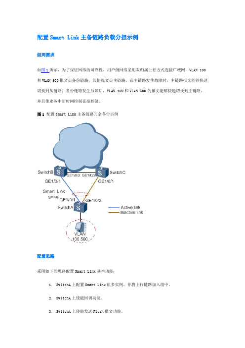
如图1所示,为了保证网络的可靠性,用户侧网络采用双归属上行方式连接广域网,VLAN 100和VLAN 500报文走备份链路,其他报文走主链路。在主链路发生故障时,主链路报文能够快速切换到从链路;备份链路发生故障后,VLAN 100和VLAN 500的报文能够快速切换到主链路。并且使业务中断时间控制在毫秒级。
GigabitEthernet1/0/1 MasterActive1 2009/01/05 10:33:46 UTC+05:00
GigabitEthernet1/0/2 SlaveInactive0 0000/00/00 00:00:00 UTC+05:00
配置文件
设备SwitchA的配置文件
#
sysname SwitchA
#
vlan batch 10 100 500
#
stp region-configuration
instance 10 vlan 100 500
active region-configuration
#
interface GigabitEthernet1/0/1
port link-type trunk
port trunk allow-pass vlan 10 100 500
[SwitchC-GigabitEthernet1/0/2]quit
23.验证配置结果
# 使用display smart-link group命令查看SwitchA上的Smart Link组信息。如果显示如下信息,则表示配置成功。
Smart Link组功能已经使能
回切时间为30秒
控制VLAN编号为10
思科路由器设置界面
思科路由器设置界面思科路由器设置界面思科路由器大家也习惯叫为Linksys路由器,是国内用户使用很多的路由器品牌。
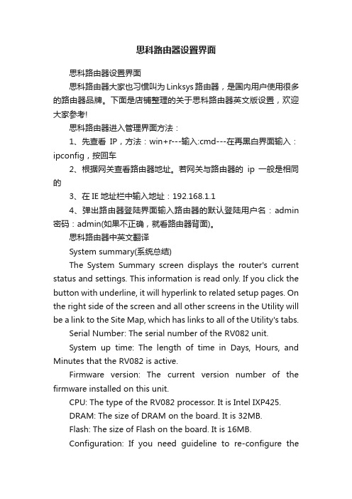
下面是店铺整理的关于思科路由器英文版设置,欢迎大家参考!思科路由器进入管理界面方法:1、先查看IP,方法:win+r---输入:cmd---在再黑白界面输入:ipconfig,按回车2、根据网关查看路由器地址。
若网关与路由器的ip一般是相同的3、在IE地址栏中输入地址:192.168.1.14、弹出路由器登陆界面输入路由器的默认登陆用户名:admin 密码:admin(如果不正确,就看路由器背面)。
思科路由器中英文翻译System summary(系统总结)The System Summary screen displays the router's current status and settings. This information is read only. If you click the button with underline, it will hyperlink to related setup pages. On the right side of the screen and all other screens in the Utility will be a link to the Site Map, which has links to all of the Utility's tabs.Serial Number: The serial number of the RV082 unit.System up time: The length of time in Days, Hours, and Minutes that the RV082 is active.Firmware version: The current version number of the firmware installed on this unit.CPU: The type of the RV082 processor. It is Intel IXP425.DRAM: The size of DRAM on the board. It is 32MB.Flash: The size of Flash on the board. It is 16MB.Configuration: If you need guideline to re-configure therouter, you may launch Wizard.Port Statistics: Users can click the port number from port diagram to see the status of the selected port该系统总的屏幕显示路由器的当前状态和设置。
- 1、下载文档前请自行甄别文档内容的完整性,平台不提供额外的编辑、内容补充、找答案等附加服务。
- 2、"仅部分预览"的文档,不可在线预览部分如存在完整性等问题,可反馈申请退款(可完整预览的文档不适用该条件!)。
- 3、如文档侵犯您的权益,请联系客服反馈,我们会尽快为您处理(人工客服工作时间:9:00-18:30)。
Table of Contents1 Smart Link Configuration Commands·····································································································1-1Smart Link Configuration Commands·····································································································1-1 display smart-link flush····················································································································1-1 display smart-link group···················································································································1-2 flush enable·····································································································································1-3 port···················································································································································1-3 port smart-link group························································································································1-4 preemption delay·····························································································································1-5 preemption mode·····························································································································1-6 protected-vlan··································································································································1-7 reset smart-link statistics·················································································································1-8 smart-link flush enable·····················································································································1-8 smart-link group·······························································································································1-91 Smart Link Configuration CommandsSmart Link Configuration Commandsdisplay smart-link flushSyntaxdisplay smart-link flushViewAny viewDefault Level1: Monitor levelParametersNoneDescriptionUse the display smart-link flush command to display information about the received flush messages. Examples# Display information about the received flush messages.<Sysname> display smart-link flushReceived flush packets : 10Receiving interface of the last flush packet : GigabitEthernet1/1/1Receiving time of the last flush packet : 19:19:03 2008/06/27Device ID of the last flush packet : 000f-e200-8500Control VLAN of the last flush packet : 1Table 1-1 display smart-link flush command output descriptionField DescriptionReceived flush packets Total number of received flush messagesReceiving interface of the last flush packet The port that received the last flush messageReceiving time of the last flush packet Time when the last flush message was received Device ID of the last flush packet Device ID carried in the last flush messageControl VLAN of the last flush packet Control VLAN ID carried in the last flush messagedisplay smart-link groupSyntaxdisplay smart-link group { group-id | all }ViewAny viewDefault Level1: Monitor levelParametersgroup-id: Smart link group ID, in the range of 1 to 6.all: Displays information about all smart link groups.DescriptionUse the display smart-link group command to display information about the specified or all smart link groups.Examples# Display information about smart link group 1.<Sysname> display smart-link group 1Smart link group 1 information:Device ID: 000f-e200-8500Preemption mode: ROLEPreemption delay: 1(s)Control VLAN: 1Protected VLAN: Reference Instance 0 to 2, 4Member Role State Flush-count Last-flush-time-------------------------------------------------------------------------------GigabitEthernet1/1/1 MASTER ACTVIE 1 16:37:20 2008/04/21GigabitEthernet1/1/3 SLAVE STANDBY 2 17:45:20 2008/04/21Table 1-2 display smart-link group command output descriptionField DescriptionSmart link group 1 information Information about smart link group 1Device ID Device IDPreemption mode Preemption mode, which can be role for preemption enabled or none for preemption disabled.Preemption delay Preemption delay time, in seconds Control-VLAN Control VLAN IDProtected VLAN Protected VLANs of the smart link group. Referenced MSTIs are displayed here. To view the VLANs mapped to the referenced MSTIs, use the display stp region-configuration command.Member Member port of the smart link groupField Description Role Port role: master or slaveState Port state: active or standbyFlush-count Number of transmitted flush messagesLast-flush-time The time when the last flush message was transmitted (NA indicates that no flush message has been transmitted)flush enableSyntaxflush enable [ control-vlan vlan-id]undo flush enableViewSmart link group viewDefault Level2: System levelParameterscontrol-vlan vlan-id: Specifies the control VLAN used for transmitting flush messages. The vlan-id argument ranges from 1 to 4094.DescriptionUse the flush enable command to enable flush update.Use the undo flush enable command to disable flush update.By default, flush update is enabled for smart link groups and VLAN 1 is used for flush message transmission.Note that, you need to configure different control VLANs for different smart link groups.Related commands: smart-link flush enable.Examples# Enable flush update for smart link group 1.<Sysname> system-view[Sysname] smart-link group 1[Sysname-smlk-group1] flush enableportSyntaxport interface-type interface-number { master | slave }undo port interface-type interface-numberViewSmart link group viewDefault Level2: System levelParametersinterface-type interface-number: Port type and port number. This must be an Ethernet port.master: Specifies a port as the master port.slave: Specifies a port as the slave port.DescriptionUse the port command to assign the specified port as the master or slave port of the current smart link group.Use the undo port command to remove the specified port from the smart link group.Note that:z Disable STP and RRPP on the ports you want to add to the smart link group, and make sure that the ports are not member ports of any aggregation group or service loopback group. On the otherhand, you cannot enable STP or RRPP on a smart link group member port or assign a smart linkgroup member port to an aggregation group or service loopback group.z You can assign a port to a smart link group with the port smart-link group command in Ethernet port view.Related commands: port smart-link group.Examples# Configure GigabitEthernet1/1/1 as the slave port of smart link group 1.<Sysname> system-view[Sysname] interface gigabitethernet 1/1/1[Sysname-GigabitEthernet1/1/1] undo stp enable[Sysname-GigabitEthernet1/1/1] quit[Sysname] smart-link group 1[Sysname-smlk-group1] protected-vlan reference-instance 0[Sysname-smlk-group1] port gigabitethernet 1/1/1 slaveport smart-link groupSyntaxport smart-link group group-id{ master | slave }undo port smart-link group group-idViewEthernet port viewDefault Level2: System levelgroup-id: Smart link group ID, in the range of 1 to 6.master: Specifies the port as the master port.slave: Specifies the port as the slave port.DescriptionUse the port smart-link group command to configure the current port as a member of the specified smart link group.Use the port smart-link group command to remove the port from the specified smart link group.Note that:z Disable STP and RRPP on the ports you want to add to the smart link group, and make sure that the ports are not member ports of any aggregation group or service loopback group. On the otherhand, you cannot enable STP or RRPP on a smart link group member port or assign a smart linkgroup member port to an aggregation group or service loopback group.z You can assign a port to a smart link group with the port command in smart link group view.Related commands: port.Examples# Configure GigabitEthernet1/1/1 as the master port of smart link group 1.<Sysname> system-view[Sysname] smart-link group 1[Sysname-smlk-group1] protected-vlan reference-instance 0[Sysname-smlk-group1] quit[Sysname] interface gigabitethernet 1/1/1[Sysname-GigabitEthernet1/1/1] undo stp enable[Sysname-GigabitEthernet1/1/1] port smart-link group 1 masterpreemption delaySyntaxpreemption delay delay-timeundo preemption delayViewSmart link group viewDefault Level2: System levelParametersdelay-time: Preemption delay (in seconds), in the range of 0 to 300.Use the preemption delay command to set the preemption delay. When role preemption is enabled, after the preemption delay is set, the master port waits for some time before taking over, so as to collaborate with the switchover of upstream devices.Use the undo preemption delay command to restore the default.By default, the preemption delay is 1 second.Note that, the preemption delay configuration takes effect only after role preemption is enabled.Related commands: preemption mode.Examples# Enable role preemption and set the preemption delay to 10 seconds.<Sysname> system-view[Sysname] smart-link group 1[Sysname-smlk-group1] preemption mode role[Sysname-smlk-group1] preemption delay 10preemption modeSyntaxpreemption mode roleundo preemption modeViewSmart link group viewDefault Level2: System levelParametersrole: Configures the role preemption mode, which enables the master port to preempt the slave port in active state.DescriptionUse the preemption mode command to enable the role preemption mode.Use the undo preemption mode command to restore the default.By default, role preemption is disabled.Examples# Enable the role preemption mode.<Sysname> system-view[Sysname] smart-link group 1[Sysname-smlk-group1] preemption mode roleprotected-vlanSyntaxprotected-vlan reference-instance instance-id-listundo protected-vlan [ reference-instance instance-id-list]ViewSmart link group viewDefault Level2: System levelParametersreference-instance instance-id-list: Specifies the MSTIs to be referenced in the form of instance-id-list = {instance-id [ to instance-id ] }&<1-10>, where the range of the instance-id argument is as specified in the command configuring MSTIs and &<1-10> indicates that you can provide up to ten MSTIs or MSTI lists.DescriptionUse the protected-vlan command to configure protected VLANs for a smart link group by referencing MSTIs. You can use the display stp region-configuration command to view the VLANs mapped to the referenced MSTIs.Use the undo protected-vlan command to remove the specified protected VLANs from a smart link group by referencing the specified MSTIs. If no MSTI is specified, all the protected VLANs of the smart link group are removed.By default, no protected VLAN is configured for a smart link group.Note that:z Before assigning ports to a smart link group, configure protected VLANs for the smart link group.z You can remove all protected VLANs from a smart link group when the group is empty but not aftera member port is assigned to it.z Removing a smart link group also removes its protected VLANs.z If the VLAN(s) mapped to a referenced MSTI changes, the protected VLAN(s) change accordingly.z The VLANs that the member ports of a smart link group belong to must be configured as the protected VLANs of the smart link group.Related commands: smart-link group, display stp region-configuration in MSTP Commands in this manual.Examples# Configure the VLANs mapped to MSTIs 1 through 10 and MSTI 12 as the protected VLANs of smart link group 1.<Sysname> system-view[Sysname] smart-link group 1[Sysname-smlk-group1] protected-vlan reference-instance 1 to 10 12reset smart-link statisticsSyntaxreset smart-link statisticsViewUser viewDefault Level2: System levelParametersNoneDescriptionUse the reset smart-link statistics command to clear the statistics about flush messages.Examples# Clear the statistics about flush messages.<Sysname> reset smart-link statisticssmart-link flush enableSyntaxsmart-link flush enable [ control-vlan vlan-id-list]undo smart-link flush enable [ control-vlan vlan-id-list]ViewEthernet port view, OLT port viewDefault Level2: System levelParameterscontrol-vlan vlan-id-list: Specifies the control VLANs used for receiving flush messages. The vlan-id-list is expressed in the form of vlan-id-list = { vlan-id [ to vlan-id ] }&<1-10>, where the vlan-id argument ranges from 1 to 4094 and &<1-10> indicates that you can provide up to ten VLAN IDs or VLAN ID lists.DescriptionUse the smart-link flush enable command to configure a VLAN for receiving flush messages, that is, a receive control VLAN, on a port in Ethernet interface view or on all ports in system view.Use the undo smart-link flush enable command to disable flush message processing.By default, flush messages are not processed.Note that:z If no VLAN is specified, VLAN 1 applies.z This command cannot be used on member port of an aggregation group or service loopback group.Related commands: flush enable.Examples# Enable GigabitEthernet1/1/1 to process the flush messages received in VLAN 1.<Sysname> system-view[Sysname] interface gigabitethernet 1/1/1[Sysname-GigabitEthernet1/1/1] smart-link flush enable# Enable Olt1/0/1 to process the flush messages received in VLAN 1.<Sysname> system-view[Sysname] interface olt 1/0/1[Sysname-Olt1/0/1] smart-link flush enablesmart-link groupSyntaxsmart-link group group-idundo smart-link group group-idViewSystem viewDefault Level2: System levelParametersgroup-id: Smart link group ID, in the range of 1 to 6.DescriptionUse the smart-link group command to create a smart link group and enter smart link group view.Use the undo link-aggregation group command to remove a smart link group.Note that a smart link group with member ports cannot be removed.Examples# Create smart link group 1 and enter smart link group view.<Sysname> system-view[Sysname] smart-link group 1[Sysname-smlk-group1]。