PIM组播协议集模式
组播pim 原理

组播pim 原理
PIM(Protocol Independent Multicast)称为协议无关组播。
作为组播路由解决方案,它直接利用单播路由表的路由信息,对组播报文执行RPF(Reverse Path Forwarding,逆向路径转发)检查,检查通过后创建组播路由表项,从而转发组播报文。
PIM-DM(PIM-Dense Mode,协议无关组播-密集模式)基本工作原理:PIM-DM使用“推(Push)模式”转发组播报文,一般应用于组播组成员规模相对较小、相对密集的网络。
其关键工作机制包括邻居发现、扩散、剪枝、嫁接、断言:
1. 邻居发现:路由器通过周期性地向所有PIM路由器(224.0.0.13)以组播方式发送PIM Hello报文,以发现PIM邻居,维护各路由器之间的PIM邻居关系,从而构建和维护SPT。
2. 扩散:当PIM-DM网络中出现活跃的组播源之后,组播源发送的组播报文将在全网内扩散。
当PIM路由器接收到组播报文,根据单播路由表进行RPF检查通过后,就会在该路由器上创建(S,G)表项,并将该报文向网络中的所有下游节点转发。
3. 剪枝:当PIM路由器接收到组播报文后,RPF检查通过,但是下游网段没有组播报文需求。
此时PIM路由器会向上游发送剪枝报文,通知上游路由器禁止相应下游接口的转发,将其从(S,G)表项的下游接口列表中删除。
4. 嫁接:PIM-DM通过嫁接机制,使有新组成员加入的网段快速得到组播报文。
叶子路由器通过IGMP了解到与其相连的用户网段上,组播组G有新的组成员加入。
随后叶子路由器会向上游发送Graft报文,请求上游路由器恢复相应出接口转发,将其添加在(S,G)表项下游接口列表中。
PIM技术介绍-2017.04.18

PIM技术介绍目录1 PIM简介 (2)1.1 PIM-DM 简介 (2)1.2 PIM-DM 工作机制 (2)1.2.1邻居发现 (2)1.2.2构建SPT (3)1.2.3嫁接 (3)1.2.4断言 (4)1.3 PIM-SM 简介 (4)1.4 PIM-SM 工作机制 (5)1.4.1邻居发现 (5)1.4.2DR 选举 (5)1.4.3RP发现 (6)1.4.4构建RPT (8)1.4.5组播源注册 (8)1.4.6RPT 向SPT 切换 (9)1.4.7断言 (9)1.5 SSM 模型在PIM 中的实现 (10)1.5.1邻邻居发现 (10)1.5.2DR 选举 (10)1.5.3构建SPT (10)2 PIM协议报文格式 (12)2.1 PIM报文通用格式 (12)2.2 PIM Hello消息格式 (13)2.3 PIM Register消息格式 (15)2.4 PIM Register-Stop消息格式 (17)2.5 PIM Join/Prune消息格式 (18)2.6 PIM Graft/Graft-Ack消息格式 (21)2.7 PIM Bootstrap消息格式 (23)2.8 PIM Assert消息格式 (26)2.9 PIM C-RP Advertisement消息格式 (27)3 组播相关概念 (30)3.1 IP组播三种的传递方式 (30)3.2 IP组播技术体系结构 (30)1 PIM简介PIM 是Protocol Independent Multicast(协议无关组播)的简称,表示可以利用静态路由或者任意单播路由协议(包括RIP、OSPF、IS-IS、BGP 等)所生成的单播路由表为IP 组播提供路由。
组播路由与所采用的单播路由协议无关,只要能够通过单播路由协议产生相应的组播路由表项即可。
PIM 借助RPF(Reverse PathForwarding,逆向路径转发)机制实现对组播报文的转发。
PIM组播协议密集模式
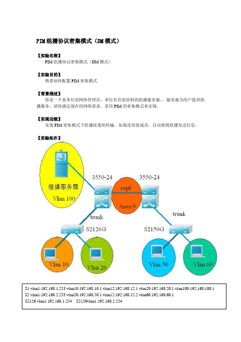
PIM组播协议密集模式(DM模式)【实验名称】PIM组播协议密集模式(DM模式)【实验目的】熟悉如何配置PIM密集模式【背景描述】你是一个某单位的网络管理员,单位有存放资料的组播服务器,,服务器为用户提供组播服务,请你满足现在的网络需求。
采用PIM的密集模式来实现。
【实现功能】实现PIM密集模式下组播流量的传输,如果没有组成员,自动修剪组播发送信息。
【实验拓扑】【实验设备】S3550-24(2台)、S2126G(1台)、S2150G(1台)、PC(4台)【实验步骤】第一步:基本配置switch(config)#hostname S1S1(config)#vlan 10 ! 创建一个vlan10S1(config-vlan)#exiS1(config)#vlan 12S1(config-vlan)#exiS1(config)#vlan 20S1(config-vlan)#exiS1(config)#vlan 100S1(config-vlan)#exiS1(config)#interface f0/24S1(config-if)#switchport mode trunk !把f0/24接口作为trunk接口S1(config-if)#switchport trunk allowed vlan remove 100 ! trunk链路不传输vlan 100的信息S1(config)#interface vlan 1S1(config-if)#ip address 192.168.1.253 255.255.255.0S1(config-if)#no shutdownS1(config)#interface vlan 10S1(config-if)#ip address 192.168.10.1 255.255.255.0 !创建一个SVI地址S1(config-if)#no shutdownS1(config)#interface vlan 12S1(config-if)#ip address 192.168.12.1 255.255.255.0S1(config-if)#no shutdownS1(config)#interface vlan 20S1(config-if)#ip address 192.168.20.1 255.255.255.0S1(config-if)#no shutdownS1(config)#interface vlan 100S1(config-if)#ip address 192.168.100.1 255.255.255.0S1(config-if)#no shutdownS1(config)#interface fastethernet f0/1 !把接口加入到vlan 10S1(config-if)#switchport access vlan 10S1(config)#interface fastethernet f0/2S1(config-if)#switchport access vlan 20S1(config)#interface fastethernet f0/12S1(config-if)#switchport access vlan 12switch(config)#hostname S2S2(config)#vlan 12S2(config-vlan)#exiS2(config)#vlan 50S2(config-vlan)#exiS2(config)#vlan 60S2(config-vlan)#exiS2(config)#vlan 100S2(config-vlan)#exiS2(config)#interface f0/24S2(config-if)#switchport mode trunkS2(config)#interface vlan 1S2(config-if)#ip address 192.168.2.253 255.255.255.0 S2(config-if)#no shutdownS2(config)#interface vlan 12S2(config-if)#ip address 192.168.12.2 255.255.255.0 S2(config)#interface vlan 50S2(config-if)#ip address 192.168.50.1 255.255.255.0 S2(config-if)#no shutdownS2(config)#interface vlan 60S2(config-if)#ip address 192.168.60.1 255.255.255.0 S2(config-if)#no shutdownS2(config)#interface fastethernet f0/1S2(config-if)#switchport access vlan 50S2(config)#interface fastethernet f0/2S2(config-if)#switchport access vlan 60S2(config)#interface fastethernet f0/12S2(config-if)#switchport access vlan 12switch(config)#hostname S2126S2126(config)#vlan 10S2126(config-vlan)#exiS2126(config)#vlan 20S2126(config-vlan)#exiS2126(config)#interface f0/1S2126(config-if)#switchport access vlan 10S2126(config)#interface f0/2S2126(config-if)#switchport access vlan 20S2126(config)#interface vlan 1S2126(config-if)#ip address 192.168.1.254S2126(config)#interface fastethernet 0/24S2126(config-if)#switchport mode trunkswitch(config)#hostname S2150S2150(config)#vlan 50S2150(config-vlan)#exiS2150(config)#vlan 60S2150(config-vlan)#exiS2150(config-if)#switchport access vlan 50S2150(config)#interface f0/2S2150(config-if)#switchport access vlan 60S2150(config)#interface vlan 1S2150(config-if)#ip address 192.168.2.254S2150(config)#interface fastethernet 0/24S2150(config-if)#switchport mode trunk第二步:配置路由协议S1(config)#router ospf ! 开启ospf进程S1(config-router)#network 192.168.1.0 0.0.0.255 area 0 !将网段加入到区域0 S1(config-router)#network 192.168.10.0 0.0.0.255 area 0S1(config-router)#network 192.168.12.0 0.0.0.255 area 0S1(config-router)#network 192.168.20.0 0.0.0.255 area 0S1(config-router)#network 192.168.100.0 0.0.0.255 area 0S2(config)#router ospfS2(config-router)#network 192.168.2.0 0.0.0.255 area 0S2(config-router)#network 192.168.12.0 0.0.0.255 area 0S2(config-router)#network 192.168.50.0 0.0.0.255 area 0S2(config-router)#network 192.168.60.0 0.0.0.255 area 0第三步:配置组播S1(config)# ip multicast-routing !开启组播功能S1(config)#interface vlan 1S1(config-if)#ip pim !默认为DM模式S1(config)#interface vlan 10S1(config-if)#ip pimS1(config)#interface vlan 12S1(config-if)#ip pimS1(config)#interface vlan 20S1(config-if)#ip pimS1(config)#interface vlan 100S1(config-if)#ip pimS2(config)# ip multicast-routingS2(config)#interface vlan 1S2(config-if)#ip pimS2(config)#interface vlan 12S2(config-if)#ip pimS2(config)#interface vlan 50S2(config-if)#ip pimS2(config-if)#ip pimS2126(config)#ip igmp profile 1 !进入igmp配置文件模式S2126(config-profile)#deny !允许所有的组播组通过。
什么是组播?让我们一起解密组播协议(IGMP、PIM)

什么是组播?让我们⼀起解密组播协议(IGMP、PIM)写在前⾯:本⼈是⼀名计算机系⼤⼆的学⽣,会不定时的将我的学习笔记分享给⼤家!如果需要更多的学习资源可以通过我的⾃⾏下载!⽬录组播技术传统的点到点单播存在的问题重复流量过多消耗设备资源、带宽资源难以保证传输质量概述信息发送者:组播源接受相同的信息接受这过程⼀个组播组,并且接受者都是定义:⼀点发出,多点接应优势提⾼效率优化性能分布式应⽤缺点基于udp尽⼒⽽为报⽂重复报⽂失序缺少拥塞避免机制61、ip组播(1) 对于IP 组播,需要关注下列问题:组播源将组播信息传输到哪⾥?即组播寻址机制;⽹络中有哪些接收者?即主机注册;这些接收者需要从哪个组播源接收信息?即组播源发现;组播信息如何传输?即组播路由。
(2) IP 组播属于端到端的服务,组播机制包括以下四个部分:寻址机制:借助组播地址,实现信息从组播源发送到⼀组接收者;主机注册:允许接收者主机动态加⼊和离开某组播组,实现对组播成员的管理;组播路由:构建组播报⽂分发树(即组播数据在⽹络中的树型转发路径),并通过该分发树将报⽂从组播源传输到接收者;组播应⽤:组播源与接收者必须安装⽀持视频会议等组播应⽤的软件,TCP/IP 协议栈必须⽀持组播信息的发送和接收。
为了让组播源和组播组成员进⾏通信,需要提供⽹络层组播地址,即IP 组播地址。
同时必须存在⼀种技术将IP 组播地址映射为链路层的组播MAC 地址。
(3) IP 组播地址IANA(Internet Assigned Numbers Authority,互联⽹编号分配委员会)将D类地址空间分配给IPv4组播使⽤,范围从224.0.0.0到239.255.255.255,具体分类及其含义如下表所⽰。
组播地址D类地址范围含义224.0.0.0-224.0.0.255为路由协议预留的永久组地址224.0.1.0-231.255.255.255 /233.0.0.0-238.255.255.255⽤户可⽤的asm临时组地址,全⽹范围有效232.0.0.0-232.255.255.255⽤户可⽤ssm临时组地址,全⽹范围内有效239.0.0.0-239.255.255.255⽤户可⽤的asm临时组地址,尽在特定的本地管理域内有效,陈伟本地管理组播地址D类地址范围含义IPv4 组播地址的范围及含义说明:组播组中的成员是动态的,主机可以在任何时刻加⼊或离开组播组。
PIM

组播路由协议PIM-SM 概述PIM-SM (Protocol Independent Multicast-Sparse Mode)––––––独立于协议的组播稀疏模式。
PIM,独立于协议,这主要是指PIM不依赖于某种特定的单播路由协议,它只是利用单播路由协议建立起来的单播路由表来完成RPF校验,而非维护一个组播路由表来实现组播的转发。
因为PIM不需要保持自己的路由表,所以它不需要象其它协议那样发送或接收组播路由更新,这样PIM的开销也就低了许多。
以下我将结合例子来简单讲述PIM-SM协议:一.P IM-SM的工作过程(共享树的加入剪枝)PIM-SM的操作是围绕着一个单向的共享树来展开的,这里的单向是指:从源到接收者方向。
在共享树上,有一个根节点----RP,共享树上的组播数据流要依赖于RP来向下转发,因此共享树也叫RP树,通常称作RPT。
那么源的数据流是如何到达接收者的呢?见下图:ReceiverB是个接收者,想接收HostA的数据流,则它向路由器C发送一个IGMP加入报文(该报文中包含一个组播组,即B想接收的那个组播流的多播地址),RouterC收到这个加入报文后,它要检查看是否存在有关于该多播地址的路由条目,没有,则创建一个(*,G)路由条目(这里的G就是目标多播组的组地址),并将收到加入报文的接口添加在这个路由条目的出接口中。
同时这也引发了RouterC向RP(图中的RouterD)发送一个PIM(*,G)加入消息,以便能够加入共享树。
至于routerC 是如何知道RP的,我们将在以后讨论。
RP收到这个(*,G)加入消息,也检查看是否存在有关于该多播地址的路由条目,有则将收到消息的接口加入到相应条目的出接口表中(即自己与RouterC相连的接口),如果没有相应的路由条目,则创建,并也在其出接口表中添加收到消息的接口。
其实组播路由器在转发组播数据流的时候,并不关心其下面有多少个接收者,他们分别位于何处,它只关心组播数据流是否有相应的出接口,有就将它们从出接口转发出去,没有就丢掉。
组播路由协议

组播路由协议组播路由协议(Multicast Routing Protocol)是一种网络协议,用于支持组播传输,将数据从一个源节点传输到多个目的节点。
组播路由协议通过建立一棵组播树来实现数据的传输,其中源节点作为根节点,目的节点作为叶子节点。
组播路由协议有多种类型,常见的包括DVMRP、IGMP、PIM和MOSPF等。
每种协议都有各自的特点和适用场景。
其中,Distance Vector Multicast Routing Protocol(DVMRP)是一种基于距离向量的组播路由协议。
它使用了类似于BGP的距离矩阵来选择最佳的路径,并通过向邻居节点广播消息来更新路由表。
DVMRP适用于小型网络,但在大型网络中可能产生大量的控制消息。
Internet Group Management Protocol(IGMP)是一种用于在主机和组播路由器之间交换组播组信息的协议。
它允许主机加入和离开组播组,并向路由器报告组播组成员。
IGMP采用了查询-报告机制,通过查询消息和报告消息来维护组播组的成员关系。
Protocol Independent Multicast(PIM)是一种独立于底层网络的组播路由协议。
它可以与各种底层网络协议一起使用,如IP、ATM和Frame Relay等。
PIM使用了两种模式:稠密模式(Dense Mode)和稀疏模式(Sparse Mode)。
稠密模式适用于具有大量组播组成员的网络,而稀疏模式适用于成员分布较不密集的网络。
Multicast Open Shortest Path First(MOSPF)是一种基于OSPF协议的组播路由协议。
它通过向OSPF协议添加组播扩展来支持组播传输。
MOSPF使用与OSPF相同的链路状态数据库(LSDB)和最短路径树(SPF)算法来计算最优的组播路径。
无论是哪种组播路由协议,其基本目标是找到一条最佳的路径,以最小的开销实现数据的组播传输。
pim协议
pim协议PIM(Protocol Independent Multicast)协议是一种网络组播协议,旨在实现高效的组播数据传输。
PIM协议并不依赖于任何特定的单播协议,而是可以与各种单播协议结合使用。
它可以在不同的网络环境下实现多播数据的传输,包括以IPv4和IPv6为基础的网络。
PIM协议的主要目标是实现高效的组播数据传输,以减少网络带宽的消耗和提高数据传输的速度。
PIM协议使用两种基本的路由协议来实现组播转发:PIM-DM(PIM-Dense Mode)和PIM-SM(PIM-Sparse Mode)。
PIM-DM是一种基于洪泛(flooding)的路由协议,适用于网络中的密集型组播场景。
当组播数据包到达一个路由器时,该路由器会将数据包发送到所有的接口上,直到数据包到达组播组的所有成员。
然而,这种方法会产生大量的数据副本,造成网络带宽的浪费。
因此,在网络拓扑中使用PIM-DM协议需要谨慎考虑。
与之相对的,PIM-SM采用一种树状结构的路由方式,只在需要的时候才将组播数据发送到具体的接口。
PIM-SM通过建立组播树(Multicast Tree)来实现组播数据的传输。
这个树的根节点是源节点,叶节点是接收组播数据的成员节点。
PIM-SM 协议使用广播及其他技术来构建和维护组播树,以动态地调整组播数据的传输路径。
这种方式可以有效地减少组播数据在网络中的传播范围,节约了网络资源的开销。
除了PIM-DM和PIM-SM,还有扩展的PIM协议:PIM-SSM (PIM-Source Specific Multicast)和PIM-BSR(PIM-Bootstrap Router)。
PIM-SSM是一种源特定的组播协议,只允许源IP 地址和组播组的IP地址相匹配的数据通过,极大地减少了组播数目。
PIM-BSR则是用来识别和维护网络中的组播源和组播组的协议。
总而言之,PIM协议是一种实现高效组播数据传输的协议。
组播 ---PIM
实验五、配置PIM auto-rp环境:三台路由器串口相连,其它的配置如图所示要求:1. R1,R2,R3配置ospf 并把所有接口加入到area 02.配置R1为rp,配置R2为映射代理,把R3加入239.3.3.3组3.练习本课所有show命令步骤一:在每个路由器上配置1个loopback 口,并配置三台路由器接口使其连通。
R1的配置R1(config)#interface Loopback0R1(config-if)# ip address 30.1.1.1 255.255.255.0R1(config)#interface Serial0R1(config-if)# ip address 10.1.1.1 255.255.255.0R1(config-if)# clockrate 64000R1(config-if)#n o shutdownR2的配置R2(config)#interface Loopback0R2(config-if)# ip address 40.1.1.1 255.255.255.0R2(config)#interface Serial0R2(config-if)# ip address 20.1.1.1 255.255.255.0R2(config-if)#clockrate 64000R2(config-if)#no shutdownR2(config)#interface Serial1R2(config-if)# ip address 10.1.1.2 255.255.255.0R2(config-if)#no shutdownR3的配置R3(config)#interface Loopback0R3(config-if)# ip address 50.1.1.1 255.255.255.0R3(config)#interface Serial1R3(config-if)# ip address 20.1.1.2 255.255.255.0R3(config-if)#no shutdown步骤二:配置ospf路由协议,使其连通R1的配置R1(config)#router ospf 1R1(config-router)# network 10.1.1.0 0.0.0.255 area 0R1(config-router)# network 30.1.1.0 0.0.0.255 area 0R2的配置R2(config)#router ospf 1R2(config-router)#network 10.1.1.0 0.0.0.255 area 0R2(config-router)# network 20.1.1.0 0.0.0.255 area 0R2(config-router)# network 40.1.1.0 0.0.0.255 area 0R3的配置R3(config)#router ospf 1R3(config-router)# network 20.1.1.0 0.0.0.255 area 0R3(config-router)# network 50.1.1.0 0.0.0.255 area 0步骤三:配置R1为rp,配置R2为映射代理,把R3加入239.3.3.3组R1的配置R1(config)#ip multicast-routing →启用多播协议R1(config)#interface Loopback0R1(config-if)#ip pim sparse-mode →接口PIM模式为稀疏R1(config)#interface Serial0R1(config-if)#ip pim sparse-modeR1(config)#ip pim send-rp-announce Loopback0 scope 5 →指定R1为RPR2的配置R2(config)#ip multicast-routingR2(config)#interface Loopback0R2(config-if)#ip pim sparse-modeR2(config)#interface Serial0R2(config-if)#ip pim sparse-modeR2(config)#interface Serial1R2(config-if)#ip pim sparse-modeR2(config)#ip pim send-rp-discovery Loopback0 scope 5 →将R2指定为映射代理R3的配置R3(config)#ip multicast-routingR3(config)#interface Loopback0R3(config-if)#ip pim sparse-modeR3(config-if)#ip igmp join-group 239.3.3.3 →将此接口加入到组239.3.3.3R3(config)#interface Serial1R3(config-if)#ip pim sparse-mode步骤四:查看组播路由表R1#sh ip mroute 239.3.3.3IP Multicast Routing TableFlags: D - Dense, S - Sparse, B - Bidir Group, s - SSM Group, C - Connected, L - Local, P - Pruned, R - RP-bit set, F - Register flag,T - SPT-bit set, J - Join SPT, M - MSDP created entry,X - Proxy Join Timer Running, A - Candidate for MSDP Advertisement,U - URD, I - Received Source Specific Host Report, Z - Multicast TunnelY - Joined MDT-data group, y - Sending to MDT-data groupOutgoing interface flags: H - Hardware switchedTimers: Uptime/ExpiresInterface state: Interface, Next-Hop or VCD, State/Mode(*, 239.3.3.3), 00:37:56/stopped, RP 30.1.1.1, flags: SIncoming interface: Null, RPF nbr 0.0.0.0Outgoing interface list:Serial0, Forward/Sparse, 00:37:56/00:03:07(10.1.1.1, 239.3.3.3), 00:00:04/00:02:56, flags: P →学来对端的基于源的多播路由Incoming interface: Serial0, RPF nbr 0.0.0.0Outgoing interface list: Null(30.1.1.1, 239.3.3.3), 00:00:04/00:03:28, flags: TIncoming interface: Loopback0, RPF nbr 0.0.0.0Outgoing interface list:Serial0, Forward/Sparse, 00:00:05/00:03:24(50.1.1.1, 239.3.3.3), 00:00:12/00:03:17, flags: PXIncoming interface: Serial0, RPF nbr 10.1.1.2Outgoing interface list: NullR2#sh ip mroute 239.3.3.3IP Multicast Routing TableFlags: D - Dense, S - Sparse, B - Bidir Group, s - SSM Group, C - Connected, L - Local, P - Pruned, R - RP-bit set, F - Register flag,T - SPT-bit set, J - Join SPT, M - MSDP created entry,X - Proxy Join Timer Running, A - Candidate for MSDP Advertisement,U - URD, I - Received Source Specific Host Report, Z - Multicast TunnelY - Joined MDT-data group, y - Sending to MDT-data groupOutgoing interface flags: H - Hardware switchedTimers: Uptime/ExpiresInterface state: Interface, Next-Hop or VCD, State/Mode(*, 239.3.3.3), 00:43:06/stopped, RP 30.1.1.1, flags: SFIncoming interface: Serial1, RPF nbr 10.1.1.1Outgoing interface list:Serial0, Forward/Sparse, 00:42:48/00:03:02(20.1.1.1, 239.3.3.3), 00:00:22/00:03:07, flags: TIncoming interface: Serial0, RPF nbr 0.0.0.0, RegisteringOutgoing interface list:Serial1, Forward/Sparse, 00:00:22/00:03:07(40.1.1.1, 239.3.3.3), 00:00:23/00:03:08, flags: FTIncoming interface: Loopback0, RPF nbr 0.0.0.0, RegisteringOutgoing interface list:Serial0, Forward/Sparse, 00:00:24/00:03:06(50.1.1.1, 239.3.3.3), 00:01:39/00:01:53, flags:Incoming interface: Serial0, RPF nbr 20.1.1.2Outgoing interface list:Serial1, Forward/Sparse, 00:01:39/00:01:53R3#sh ip mroute 239.3.3.3IP Multicast Routing TableFlags: D - Dense, S - Sparse, B - Bidir Group, s - SSM Group, C - Connected, L - Local, P - Pruned, R - RP-bit set, F - Register flag,T - SPT-bit set, J - Join SPT, M - MSDP created entry,X - Proxy Join Timer Running, A - Candidate for MSDP Advertisement,U - URD, I - Received Source Specific Host Report, Z - Multicast TunnelY - Joined MDT-data group, y - Sending to MDT-data groupOutgoing interface flags: H - Hardware switchedTimers: Uptime/ExpiresInterface state: Interface, Next-Hop or VCD, State/Mode(*, 239.3.3.3), 00:46:06/stopped, RP 30.1.1.1, flags: SJCLFIncoming interface: Serial1, RPF nbr 20.1.1.1Outgoing interface list:Loopback0, Forward/Sparse, 00:46:06/00:02:27(50.1.1.1, 239.3.3.3), 00:03:54/00:03:06, flags: LFTIncoming interface: Loopback0, RPF nbr 0.0.0.0, RegisteringOutgoing interface list:Serial1, Forward/Sparse, 00:00:32/00:02:58步骤五:查看接口组播信息R1#sh ip pim int s0Address Interface Ver/ Nbr Query DR DRMode Count Intvl Prior10.1.1.1 Serial0 v2/S 1 30 1 0.0.0.0R1#sh ip pim int lo 0Address Interface Ver/ Nbr Query DR DRMode Count Intvl Prior30.1.1.1 Loopback0 v2/S 0 30 1 30.1.1.1 R2#sh ip pim int s0Address Interface Ver/ Nbr Query DR DRMode Count Intvl Prior20.1.1.1 Serial0 v2/S 1 30 1 0.0.0.0R2#sh ip pim int s1Address Interface Ver/ Nbr Query DR DRMode Count Intvl Prior10.1.1.2 Serial1 v2/S 1 30 1 0.0.0.0R2#sh ip pim int lo 0Address Interface Ver/ Nbr Query DR DRMode Count Intvl Prior40.1.1.1 Loopback0 v2/S 0 30 1 40.1.1.1 R3#sh ip pim int s1Address Interface Ver/ Nbr Query DR DRMode Count Intvl Prior20.1.1.2 Serial1 v2/S 1 30 1 0.0.0.0R3#sh ip pim int lo 0Address Interface Ver/ Nbr Query DR DRMode Count Intvl Prior50.1.1.1 Loopback0 v2/S 0 30 1 50.1.1.1 步骤六:查看组播邻居R1#sh ip pim neighborPIM Neighbor TableNeighbor Interface Uptime/Expires Ver DR Address Prio/Mode 10.1.1.2 Serial0 01:59:55/00:01:38 v2 1 / SR2#sh ip pim neiPIM Neighbor TableNeighbor Interface Uptime/Expires Ver DR Address Prio/Mode 20.1.1.2 Serial0 02:00:36/00:01:17 v2 1 / S10.1.1.1 Serial1 02:03:04/00:01:21 v2 1 / SR3#sh ip pim neighborPIM Neighbor TableNeighbor Interface Uptime/Expires Ver DR Address Prio/Mode 20.1.1.1 Serial1 02:03:21/00:01:35 v2 1 / S步骤七:查看rp映射表R1#sh ip pim rp mappingPIM Group-to-RP MappingsThis system is an RP (Auto-RP)Group(s) 224.0.0.0/4RP 30.1.1.1 (?), v2v1Info source: 40.1.1.1 (?), elected via Auto-RPUptime: 00:43:36, expires: 00:02:59R2#sh ip pim rp mappingPIM Group-to-RP MappingsThis system is an RP-mapping agent (Loopback0)Group(s) 224.0.0.0/4RP 30.1.1.1 (?), v2v1Info source: 30.1.1.1 (?), elected via Auto-RPUptime: 00:48:13, expires: 00:02:44R3#sh ip pim rp mappingPIM Group-to-RP MappingsGroup(s) 224.0.0.0/4RP 30.1.1.1 (?), v2v1Info source: 40.1.1.1 (?), elected via Auto-RPUptime: 00:50:26, expires: 00:02:03步骤八:ping 组播地址测试R1#ping 239.3.3.3Type escape sequence to abort.Sending 1, 100-byte ICMP Echos to 239.3.3.3, timeout is 2 seconds: Reply to request 0 from 20.1.1.2, 80 ms 此显示为已通Reply to request 0 from 20.1.1.2, 112 msR2#ping 239.3.3.3Type escape sequence to abort.Sending 1, 100-byte ICMP Echos to 239.3.3.3, timeout is 2 seconds: Reply to request 0 from 20.1.1.2, 56 msReply to request 0 from 20.1.1.2, 136 msReply to request 0 from 20.1.1.2, 80 msR3#ping 239.3.3.3Type escape sequence to abort.Sending 1, 100-byte ICMP Echos to 239.3.3.3, timeout is 2 seconds: Reply to request 0 from 50.1.1.1, 8 ms步骤九:查看当前配置结果R1#sh runhostname R1!ip multicast-routing!interface Loopback0ip address 30.1.1.1 255.255.255.0ip pim sparse-mode!interface Serial0ip address 10.1.1.1 255.255.255.0ip pim sparse-modeclockrate 64000!router ospf 1network 10.1.1.0 0.0.0.255 area 0network 30.1.1.0 0.0.0.255 area 0!ip pim send-rp-announce Loopback0 scope 5 endR2#sh runhostname R2!ip multicast-routing!interface Loopback0ip address 40.1.1.1 255.255.255.0ip pim sparse-mode!interface Serial0ip address 20.1.1.1 255.255.255.0ip pim sparse-modeclockrate 64000!interface Serial1ip address 10.1.1.2 255.255.255.0ip pim sparse-mode!router ospf 1network 10.1.1.0 0.0.0.255 area 0network 20.1.1.0 0.0.0.255 area 0network 40.1.1.0 0.0.0.255 area 0!ip pim send-rp-discovery Loopback0 scope 5 !endR3#sh runhostname R3!ip multicast-routing!interface Loopback0ip address 50.1.1.1 255.255.255.0ip pim sparse-modeip igmp join-group 239.3.3.3!interface Serial1ip address 20.1.1.2 255.255.255.0ip pim sparse-mode!router ospf 1network 20.1.1.0 0.0.0.255 area 0network 50.1.1.0 0.0.0.255 area 0!end多播实验(二)环境:三台路由器由串口相联,连接如下图。
PIM协议分析组播路由协议的工作原理与应用
PIM协议分析组播路由协议的工作原理与应用PIM协议(Protocol Independent Multicast)是一种用于实现组播路由的协议。
它的设计初衷是为了解决互联网上的组播通信问题。
本文将分析PIM协议的工作原理以及其在组播路由中的应用。
一、PIM协议的工作原理PIM协议是一种基于源的组播路由协议,主要用于构建组播树并实现组播数据的传输。
在PIM协议中,有两种重要的角色:组播源和组播接收者。
首先,组播源负责产生并发送组播数据。
当组播源发送组播数据时,它将该数据通过本地接口传递给PIM进程。
PIM进程将根据网络情况和配置信息,决定选择哪条出局口进行数据传输。
其次,组播接收者是指希望接收组播数据的主机。
组播接收者通过在组播组上加入的方式,表达他们的兴趣。
当接收者加入了组播组后,PIM协议将自动为其建立一条到源的最佳路径,以便接收组播数据。
PIM协议主要有两种模式:稠密模式(dense mode)和稀疏模式(sparse mode)。
稠密模式适用于组播数据较为密集的情况,而稀疏模式适用于组播数据较为稀疏的情况。
在稠密模式中,PIM协议使用洪泛(flooding)的方式来传递组播数据。
当组播源发送组播数据时,PIM协议将该数据通过所有接口传递给邻居路由器,邻居路由器再转发给它们的邻居,以此类推。
这种方式的优点是简单直接,但是在网络中会造成大量的冗余传输。
在稀疏模式中,PIM协议使用树状结构来传递组播数据,树的根节点是组播源,叶节点是组播接收者。
在建立组播树时,PIM协议使用了Rendezvous Point(RP)机制。
RP是组播树的核心节点,负责维护组播会话的状态,并指导组播数据的传输路径。
当组播源发送数据时,它会通过RP将数据传递给其他路由器,然后再由这些路由器传递给组播接收者。
稀疏模式可以减少冗余传输,提高网络效率。
二、PIM协议的应用PIM协议在组播路由中具有广泛的应用。
以下将介绍PIM协议在几个方面的具体应用。
PIM组播协议稀疏模式SM模式
你是一个某单位的网络管理员,单位有存放资料的组播服务器,,服务器为用户提供组播服务,请你满足现在的网络需求。
采用PIM的稀疏模式来实现PIM组播协议稀疏模式(SM模式)【实验名称】PIM组播协议稀疏模式(SM模式)【实验目的】熟悉如何配置PIM稀疏模式【背景描述】你是一个某单位的网络管理员,单位有存放资料的组播服务器,,服务器为用户提供组播服务,请你满足现在的网络需求。
采用PIM的稀疏模式来实现。
【实现功能】实现PIM稀疏模式下组播流量的传输,只有请求加入组才能获得组播流量【实验拓扑】【实验设备】S3550-24(2台)、S2126G(1台)、S2150G(1台)、PC(4台)【实验步骤】第一步:基本配置switch(config)#hostname S1S1(config)#vlan 10 ! 创建一个vlan10S1(config-vlan)#exiS1(config)#vlan 12S1(config-vlan)#exiS1(config)#vlan 20S1(config-vlan)#exiS1(config)#vlan 30S1(config-vlan)#exiS1(config)#vlan 100S1(config-vlan)#exiS1(config)#interface f0/24S1(config-if)#switchport mode trunk !把f0/24接口作为trunk接口S1(config-if)#switchport trunk allowed vlan remove 100 ! trunk链路不传输vlan 100的信息S1(config)#interface vlan 1S1(config-if)#ip address 192.168.1.253 255.255.255.0S1(config-if)#no shutdownS1(config)#interface vlan 10S1(config-if)#ip address 192.168.10.1 255.255.255.0S1(config-if)#no shutdownS1(config)#interface vlan 12S1(config-if)#ip address 192.168.12.1 255.255.255.0S1(config-if)#no shutdownS1(config)#interface vlan 20S1(config-if)#ip address 192.168.20.1 255.255.255.0S1(config-if)#no shutdownS1(config)#interface vlan 30S1(config-if)#ip address 192.168.30.1 255.255.255.0 S1(config-if)#no shutdownS1(config)#interface vlan 100S1(config-if)#ip address 192.168.100.1 255.255.255.0 S1(config-if)#no shutdownS1(config)#interface fastethernet f0/1S1(config-if)#switchport access vlan 10S1(config)#interface fastethernet f0/2S1(config-if)#switchport access vlan 20S1(config)#interface fastethernet f0/3S1(config-if)#switchport access vlan 30S1(config)#interface fastethernet f0/12S1(config-if)#switchport access vlan 12switch(config)#hostname S2S2(config)#vlan 12S2(config-vlan)#exiS2(config)#vlan 50S2(config-vlan)#exiS2(config)#vlan 60S2(config-vlan)#exiS2(config)#vlan 100S2(config-vlan)#exiS2(config)#interface f0/24S2(config-if)#switchport mode trunkS2(config)#interface vlan 1S2(config-if)#ip address 192.168.2.253 255.255.255.0 S2(config-if)#no shutdownS2(config)#interface vlan 12S2(config-if)#ip address 192.168.12.2 255.255.255.0 S2(config)#interface vlan 50S2(config-if)#ip address 192.168.50.1 255.255.255.0 S2(config-if)#no shutdownS2(config)#interface vlan 60S2(config-if)#ip address 192.168.60.1 255.255.255.0 S2(config-if)#no shutdownS2(config)#interface fastethernet f0/1S2(config-if)#switchport access vlan 50S2(config)#interface fastethernet f0/2S2(config-if)#switchport access vlan 60S2(config)#interface fastethernet f0/12S2(config-if)#switchport access vlan 12switch(config)#hostname S2126S2126(config)#vlan 10S2126(config-vlan)#exiS2126(config)#vlan 20S2126(config-vlan)#exiS2126(config)#interface f0/1S2126(config-if)#switchport access vlan 10 S2126(config)#interface f0/2S2126(config-if)#switchport access vlan 20 S2126(config)#interface vlan 1S2126(config-if)#ip address 192.168.1.254 S2126(config)#interface fastethernet 0/24 S2126(config-if)#switchport mode trunkswitch(config)#hostname S2150S2150(config)#vlan 50S2150(config-vlan)#exiS2150(config)#vlan 60S2150(config-vlan)#exiS2150(config)#interface f0/1S2150(config-if)#switchport access vlan 50S2150(config)#interface f0/2S2150(config-if)#switchport access vlan 60S2150(config)#interface vlan 1S2150(config-if)#ip address 192.168.2.254S2150(config)#interface fastethernet 0/24S2150(config-if)#switchport mode trunk第二步:配置路由协议S1(config)#router ospf ! 开启ospf进程S1(config-router)#network 192.168.1.0 0.0.0.255 area 0 !将网段加入到区域0 S1(config-router)#network 192.168.10.0 0.0.0.255 area 0S1(config-router)#network 192.168.12.0 0.0.0.255 area 0S1(config-router)#network 192.168.20.0 0.0.0.255 area 0S1(config-router)#network 192.168.30.0 0.0.0.255 area 0S1(config-router)#network 192.168.100.0 0.0.0.255 area 0S2(config)#router ospfS2(config-router)#network 192.168.2.0 0.0.0.255 area 0S2(config-router)#network 192.168.12.0 0.0.0.255 area 0S2(config-router)#network 192.168.50.0 0.0.0.255 area 0S2(config-router)#network 192.168.60.0 0.0.0.255 area 0第三步:配置组播S1(config)# ip multicast-routing !开启组播功能S1(config)# ip pim rp-address 192.168.30.1 !静态指定RP S1(config)#interface vlan 1S1(config-if)#ip pimS1(config-if)#ip pim sparse-mode !设置PIM模式为SM模式S1(config)#interface vlan 10S1(config-if)#ip pimS1(config-if)#ip pim sparse-modeS1(config)#interface vlan 12S1(config-if)#ip pimS1(config-if)#ip pim sparse-modeS1(config)#interface vlan 20S1(config-if)#ip pimS1(config-if)#ip pim sparse-modeS1(config)#interface vlan 100S1(config-if)#ip pimS1(config-if)#ip pim sparse-modeS2(config)# ip multicast-routingS2(config)# ip pim rp-address 192.168.30.1S2(config)#interface vlan 1S2(config-if)#ip pimS2(config-if)#ip pim sparse-modeS2(config)#interface vlan 12S2(config-if)#ip pimS1(config-if)#ip pim sparse-modeS2(config)#interface vlan 50S2(config-if)#ip pimS2(config-if)#ip pim sparse-modeS2(config)#interface vlan 60S2(config-if)#ip pimS2(config-if)#ip pim sparse-modeS2126(config)#ip igmp profile 1 !进入igmp配置文件模式S2126(config-profile)#deny !允许所有的组播组通过。
- 1、下载文档前请自行甄别文档内容的完整性,平台不提供额外的编辑、内容补充、找答案等附加服务。
- 2、"仅部分预览"的文档,不可在线预览部分如存在完整性等问题,可反馈申请退款(可完整预览的文档不适用该条件!)。
- 3、如文档侵犯您的权益,请联系客服反馈,我们会尽快为您处理(人工客服工作时间:9:00-18:30)。
PIM组播协议密集模式(DM模式)【实验名称】PIM组播协议密集模式(DM模式)【实验目的】熟悉如何配置PIM密集模式【背景描述】你是一个某单位的网络管理员,单位有存放资料的组播服务器,,服务器为用户提供组播服务,请你满足现在的网络需求。
采用PIM的密集模式来实现。
【实现功能】实现PIM密集模式下组播流量的传输,如果没有组成员,自动修剪组播发送信息。
【实验拓扑】S1 vlan1:192.168.1.253 vlan10:192.168.10.1 vlan12:192.168.12.1 vlan20:192.168.20.1 vlan100:192.168.100.1 S2 vlan1:192.168.2.253 vlan50:192.168.50.1 vlan12:192.168.12.2 vlan60:192.168.60.1S2126 vlan1:192.168.1.254 S2150vlan1:192.168.2.254【实验设备】S3550-24(2台)、S2126G(1台)、S2150G(1台)、PC(4台)【实验步骤】第一步:基本配置switch(config)#hostname S1S1(config)#vlan 10 ! 创建一个vlan10S1(config-vlan)#exiS1(config)#vlan 12S1(config-vlan)#exiS1(config)#vlan 20S1(config-vlan)#exiS1(config)#vlan 100S1(config-vlan)#exiS1(config)#interface f0/24S1(config-if)#switchport mode trunk !把f0/24接口作为trunk接口S1(config-if)#switchport trunk allowed vlan remove 100 ! trunk链路不传输vlan 100的信息S1(config)#interface vlan 1S1(config-if)#ip address 192.168.1.253 255.255.255.0S1(config-if)#no shutdownS1(config)#interface vlan 10S1(config-if)#ip address 192.168.10.1 255.255.255.0 !创建一个SVI地址S1(config-if)#no shutdownS1(config)#interface vlan 12S1(config-if)#ip address 192.168.12.1 255.255.255.0S1(config-if)#no shutdownS1(config)#interface vlan 20S1(config-if)#ip address 192.168.20.1 255.255.255.0S1(config-if)#no shutdownS1(config)#interface vlan 100S1(config-if)#ip address 192.168.100.1 255.255.255.0S1(config-if)#no shutdownS1(config)#interface fastethernet f0/1 !把接口加入到vlan 10S1(config-if)#switchport access vlan 10S1(config)#interface fastethernet f0/2S1(config-if)#switchport access vlan 20S1(config)#interface fastethernet f0/12S1(config-if)#switchport access vlan 12switch(config)#hostname S2S2(config)#vlan 12S2(config-vlan)#exiS2(config)#vlan 50S2(config-vlan)#exiS2(config)#vlan 60S2(config-vlan)#exiS2(config)#vlan 100S2(config-vlan)#exiS2(config)#interface f0/24S2(config-if)#switchport mode trunkS2(config)#interface vlan 1S2(config-if)#ip address 192.168.2.253 255.255.255.0 S2(config-if)#no shutdownS2(config)#interface vlan 12S2(config-if)#ip address 192.168.12.2 255.255.255.0 S2(config)#interface vlan 50S2(config-if)#ip address 192.168.50.1 255.255.255.0 S2(config-if)#no shutdownS2(config)#interface vlan 60S2(config-if)#ip address 192.168.60.1 255.255.255.0 S2(config-if)#no shutdownS2(config)#interface fastethernet f0/1S2(config-if)#switchport access vlan 50S2(config)#interface fastethernet f0/2S2(config-if)#switchport access vlan 60S2(config)#interface fastethernet f0/12S2(config-if)#switchport access vlan 12switch(config)#hostname S2126S2126(config)#vlan 10S2126(config-vlan)#exiS2126(config)#vlan 20S2126(config-vlan)#exiS2126(config)#interface f0/1S2126(config-if)#switchport access vlan 10S2126(config)#interface f0/2S2126(config-if)#switchport access vlan 20S2126(config)#interface vlan 1S2126(config-if)#ip address 192.168.1.254S2126(config)#interface fastethernet 0/24S2126(config-if)#switchport mode trunkswitch(config)#hostname S2150S2150(config)#vlan 50S2150(config-vlan)#exiS2150(config)#vlan 60S2150(config-vlan)#exiS2150(config-if)#switchport access vlan 50S2150(config)#interface f0/2S2150(config-if)#switchport access vlan 60S2150(config)#interface vlan 1S2150(config-if)#ip address 192.168.2.254S2150(config)#interface fastethernet 0/24S2150(config-if)#switchport mode trunk第二步:配置路由协议S1(config)#router ospf ! 开启ospf进程S1(config-router)#network 192.168.1.0 0.0.0.255 area 0 !将网段加入到区域0 S1(config-router)#network 192.168.10.0 0.0.0.255 area 0S1(config-router)#network 192.168.12.0 0.0.0.255 area 0S1(config-router)#network 192.168.20.0 0.0.0.255 area 0S1(config-router)#network 192.168.100.0 0.0.0.255 area 0S2(config)#router ospfS2(config-router)#network 192.168.2.0 0.0.0.255 area 0S2(config-router)#network 192.168.12.0 0.0.0.255 area 0S2(config-router)#network 192.168.50.0 0.0.0.255 area 0S2(config-router)#network 192.168.60.0 0.0.0.255 area 0第三步:配置组播S1(config)# ip multicast-routing !开启组播功能S1(config)#interface vlan 1S1(config-if)#ip pim !默认为DM模式S1(config)#interface vlan 10S1(config-if)#ip pimS1(config)#interface vlan 12S1(config-if)#ip pimS1(config)#interface vlan 20S1(config-if)#ip pimS1(config)#interface vlan 100S1(config-if)#ip pimS2(config)# ip multicast-routingS2(config)#interface vlan 1S2(config-if)#ip pimS2(config)#interface vlan 12S2(config-if)#ip pimS2(config)#interface vlan 50S2(config-if)#ip pimS2(config-if)#ip pimS2126(config)#ip igmp profile 1 !进入igmp配置文件模式S2126(config-profile)#deny !允许所有的组播组通过。
S2126(config)# ip igmp snooping svgl profile 1S2126(config)# ip igmp snooping svgl !设置为svgl模式S2126(config)# ip igmp snooping svgl vlan 1 mrouter learn pim-dvmrp !动态学习路由连接口S2126(config)# ip igmp snooping svgl vlan 10 mrouter learn pim-dvmrpS2126(config)# ip igmp snooping svgl vlan 20 mrouter learn pim-dvmrpS2126(config)# ip igmp snooping source-check port ! 源端口检测,默认打开。