本科毕业设计桥梁外文翻译
桥梁毕业设计外文翻译5
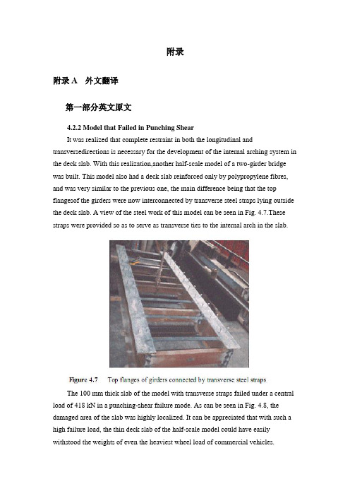
附录附录A 外文翻译第一部分英文原文4.2.2 Model that Failed in Punching ShearIt was realized that complete restraint in both the longitudinal and transversedirections is necessary for the development of the internal arching system in the deck slab. With this realization,another half-scale model of a two-girder bridge was built. This model also had a deck slab reinforced only by polypropylene fibres, and was very similar to the previous one, the main difference being that the top flangesof the girders were now interconnected by transverse steel straps lying outside the deck slab. A view of the steel work of this model can be seen in Fig. 4.7.These straps were provided so as to serve as transverse ties to the internal arch in the slab.The 100 mm thick slab of the model with transverse straps failed under a central load of 418 kN in a punching-shear failure mode. As can be seen in Fig. 4.8, the damaged area of the slab was highly localized. It can be appreciated that with such a high failure load, the thin deck slab of the half-scale model could have easily withstood the weights of even the heaviest wheel load of commercial vehicles.The model tests described above and in sub-section 4.2.1 clearly demonstrate that an internal arching action will indeed develop in a deck slab, but only if it is suitably restrained.4.2.3 Edge StiffeningA further appreciation of the deck slab arching action is provided by tests on a scale model of a skew slab-on-girder bridge. As will be discussed in sub-section 4.4.2, one transverse free edge of the deck slab of this model was stiffened by a composite steel channel with its web in the vertical plane. The other free edge was stiffened by a steel channel diaphragm with its web horizontal and connected to the deck slab through shear connectors. The deck slab near the former transverse edge failed in a mode that was a hybrid between punching shear and flexure. Tests near the composite diaphragm led to failure at a much higher load in punching shear (Bakht and Agarwal, 1993).The above tests confirmed yet again that the presence of the internal arching action in deck slabs induces high in-plane force effects which in turn demand stiffer restraint in the plane of the deck than in the out-of-plane direction.4.3 INTERNALLY RESTRAINED DECK SLABSDeck slabs which require embedded reinforcement for strength will now be referred to as internally restrained deck slabs. The state-of-art up to 1986 relating to the quantification and utilization of the beneficial internal arching action in deck slabs with steel reinforcement has been provided by Bakht and Markovic (1986). Their conclusions complemented with up-to-date information are presented in this chapter in a generally chronological order which, however, cannot be adhered to rigidlybecause of the simultaneous occurrence of some developments.4.3.1 Static Tests on Scale ModelsAbout three decades ago, the Structures Research Office of the Ministry of Transportation of Ontario (MTO), Canada, sponsored an extensive laboratory-based research program into the load carrying capacity of deck slabs; this research program was carried out at Queen's University, Kingston, Ontario. Most of this research was conducted through static tests on scale models of slab-on-girder bridges. This pioneering work is reported by Hewitt and Batchelor (1975) and later by Batchelor et al. (1985), and is summarized in the following.The inability of the concrete to sustain tensile strains, which leads to cracking, has been shown to be the main attribute which causes the compressive membrane forces to develop. This phenomenon is illustrated in Fig. 4.9 (a) which shows the part cross-section of slab-on-girder bridge under the action of a concentrated load.The cracking of the concrete, as shown in the figure, results in a net compressive force near the bottom face of the slab at each of the two girder locations. Midway between the girders, the net compressive force moves towards the top of the slab. It can be readily visualized that the transition of the net compressive force from near the top in the middle region, to near the bottom at the supports corresponds to the familiar arching action. Because of this internal arching action, the failure mode of a deck slab under a concentrated load becomes that of punching shear.If the material of the deck slab has the same stress-strain characteristics in both tension and compression, the slab will not crack and, as shown in Fig. 4.9 (b), will not develop the net compressive force and hence the arching action.In the punching shear type of failure, a frustum separates from the rest of the slab, as shown in schematically in Fig. 4.10. It is noted that in most failure tests, the diameter of the lower end of the frustrum extends to the vicinity of the girders.From analytical and confirmatory laboratory studies, it was established that the most significant factor influencing the failure load of a concrete deck slab is the confinement of the panel under consideration. It was concluded that this confinement is provided by the expanse of the slab beyond the loaded area; its degree was founddifficult to assess analytically. A restraint factor, η, was used as an empirical measure of the confinement; its value is equal to zero for the case of no confinement and 1.0 for full confinement.The effect of various parameters on the failure load can be seen in Table 4.1, which lists the theoretical failure loads for various cases. It can be seen that an increase of the restraint factor from 0.0 to 0.5 results in a very large increase in the failure load. The table also emphasizes the fact that neglect of the restraint factor causes a gross underestimation of the failure load.It was concluded that design for flexure leads to the inclusion of large amounts of unnecessary steel reinforcement in the deck slabs, and that even the minimum amount of steel required for crack control against volumetric changes in concrete is adequate to sustain modern-day, and even future, highway vehicles of North America.It was recommended that for new construction, the reinforcement in a deck slab should be in two layers, with each layer consisting of an orthogonal mesh having the same area of reinforcement in each direction. The area of steel reinforcement in each direction of a mesh was suggested to be 0.2% of the effective area of cross-section of the slab. This empirical method of design was recommended for deck slabs with certain constraints.4.3.2 Pulsating Load Tests on Scale ModelsTo study the fatigue strength of deck slabs with reduced reinforcement, five small scale models with different reinforcement ratios in different panels were tested at the Queen's University at Kingston. Details of this study are reported by Batchelor et al. (1978).Experimental investigation confirmed that for loads normally encountered in North America deck slabs with both conventional and recommended reducedreinforcement have large reserve strengths against failure by fatigue. It was confirmed that the reinforcement in the deck slab should be as noted in sub-section 4.3.1. It is recalled that the 0.2% reinforcement requires that the deck slab must have a minimum restraint factor of 0.5.The work of Okada, et al. (1978) also deals with fatigue tests on full scale models of deck slabs and segments of severely cracked slab removed from eight to ten year old bridges. The application of these test results to deck slabs of actual bridges is open to question because test specimens were removed from the original structures in such a way that they did not retain the confinement necessary for the development of the arching action.4.3.3 Field TestingAlong with the studies described in the preceding sub-section, a program of field testing of the deck slabs of in-service bridges was undertaken by the Structures Research Office of the MTO. The testing consisted of subjecting deck slabs to single concentrated loads, simulating wheel loads, and monitoring the load-deflection characteristics of the slab. The testing is reported by Csagoly et al. (1978) and details of the testing equipment are given by Bakht and Csagoly (1979).Values of the restraint factor, η, were back-calculated from measured deflections.A summary of test results, given in Table 4.2, shows that the average value of η in composite bridges is greater than 0.75, while that for non-composite bridges is 0.42. It was concluded that for new construction, the restraint factor, η, can be assumed to have a minimum value of 0.5.Bakht (1981) reports that after the first application of a test load of high magnitude on deck slabs of existing bridges, a small residual deflection was observed in most cases. Subsequent applications of the same load did not result in further residual deflections. It is postulated that the residual deflections are caused by cracking of the concrete which, as discussed earlier, accompanies the development of the internal arching action. The residual deflections after the first cycle of loading suggest that either the slab was never subjected to loads high enough to cause cracking, or the cracks have 'healed' with time.第二部分汉语翻译4.2.2 在冲切剪应力下的实效模型我们已经知道在桥面板内部拱形系统的形成中,不仅纵向而且横向也被完全约束限制是完全必要的。
桥梁工程本科毕业设计外文翻译---混凝土桥梁的结构形式

本科毕业设计外文翻译混凝土桥梁的结构形式院(系、部)名称:专业名称:学生姓名:学生学号:指导教师:The Structure of Concrete BridgePre-stressed concrete has proved to be technically advantageous, economically competitive, and esthetically superior bridges, from very short span structures using standard components to cable-stayed girders and continuous box girders with clear spans of nearly 100aft .Nearly all concrete bridges, even those of relatively short span, are now pre-stressed. Pre-casting, cast-in-place construction, or a combination of the two methods may be used .Both pre-tensioning and post tensioning are employed, often on the same project.In the United States, highway bridges generally must-meet loading ,design ,and construction requirements of the AASHTO Specification .Design requirements for pedestrian crossings and bridges serving other purposes may be established by local or regional codes and specifications .ACI Code provisions are often incorporated by reference .Bridges spans to about 100ft often consist of pre-cast integral-deck units ,which offer low initial cost ,minimum ,maintenance ,and fast easy construction ,with minimum traffic interruption .Such girders are generally pre-tensioned .The units are placed side by side ,and are often post-tensioned laterally at intermediate diaphragm locations ,after which shear keys between adjacent units are filled with non-shrinking mortar .For highway spans ,an asphalt wearing surface may be applied directly to the top of the pre-cast concrete .In some cases ,a cast-in-place slab is placed to provide composite action .The voided slabs are commonly available in depths from 15 to 21 in .and widths of 3 to 4 ft .For a standard highway HS20 loading, they are suitable for spans to about 50 ft, Standard channel sections are available in depths from 21 to 35 in a variety of widths, and are used for spans between about 20 and 60 ft .The hollow box beams-and single-tee girders are intended for longer spans up to about 100 ft.For medium-span highway bridges ,to about 120 ft ,AASHTO standard I beams are generally used .They are intended for use with a composite cast-in-place roadway slab .Such girders often combine pre-tensioning of the pre-cast member with post-tensioning of the composite beam after the deck is placed .In an effort to obtain improved economy ,some states have adopted more refined designs ,such as the State of Washington standard girders.The specially designed pre-cast girders may be used to carry a monorail transit system .The finished guide way of Walt Disney World Monorail features a series of segments, each consisting of six simply supported pre-tensioned beams ,together to from a continuous structure .Typical spans are 100 to 110 ft . Approximately half of the 337 beams used have some combination of vertical and horizontal curvatures and variable super elevation .Allbeams are hollow, a feature achieved by inserting a styro-foam void in the curved beams and by a moving mandrel in straight beam production.Pre-cast girders may not be used for spans much in excess of 120 ft because of the problems of transporting and erecting large, heavy units.On the other hand ,there is a clear trend toward the use of longer spans for bridges .For elevated urban expressways ,long spans facilitate access and minimize obstruction to activities below .Concern for environmental damage has led to the choice of long spans for continuous viaducts . For river crossings, intermediate piers may be impossible because of requirements of navigational clearance.In typical construction of this type, piers are cast-in-place, often using the slip-forming technique .A “hammerhead” section of box girder is often cast at the top of the pier, and construction proceeds in each direction by the balanced cantilever method. Finally, after the closing cast-in-place joint is made at mid-span, the structure is further post-tensioned for full continuity .Shear keys may be used on the vertical faces between segments, and pre-cast are glued with epoxy resin.The imaginative engineering demonstrated by many special techniques has extended the range of concrete construction for bridges far beyond anything that could be conceived just a few years ago .In the United States, twin curved cast-in –place segmental box girders have recently been completed for of span of 310 ft over the Eel River in northern California .Preliminary design has been completed for twin continuous box girders consisting of central 550 ft spans flanked by 390 ft side spans.Another form of pre-stressed concrete bridge well suited to long spans is the cable-stayed box girder .A notable example is the Chaco-Corrientes Bridge in Argentina .The bridges main span of 804 ft is supported by two A-frame towers, with cable stays stretching from tower tops to points along the deck .The deck itself consists of two parallel box girders made of pre-cast sections erected using the cantilever method .The tensioned cables not only provide a vertical reaction component to support the deck ,but also introduce horizontal compression to the box girders ,adding to the post-tensioning force in those members .Stress-ribbon Bridge pioneered many years ago by the German engineer Ulrich Finsterwalder. The stress-ribbon bridge carries a pipeline and pedestrians over the Rhine River with a span of 446 ft .The superstructure erection sequence was to (a) erect two pairs of cables, (b) place pre-cast slabs forming a sidewalk deck and a U under each of the sets of cables, and (c) cast-in-place concrete within the two Us. The pipeline is placed atop supports at railing height, off to one side, which greatly increases the wind speed of the structure.It is appropriate in discussing bridge forms to mention structural esthetics .The time ispast when structures could be designed on the basis of minimum cost and technical advantages alone .Bridge structures in particular are exposed for all to see .To produce a structure that is visually offensive ,as has occurred all too often in the past, is an act professional irresponsibility .Particularly for major spans ,but also for more ordinary structures ,architectural advice should be sought early in conceptual stage of the design process.混凝土梁桥的结构形式事实证明,预应力混凝土结构是在技术上先进、经济上有竞争力、符合审美学的一种先进技术。
桥梁工程毕业设计外文翻译
Review of assessment and repair of fire-damaged RChighway bridgesAbstract:This paper presents a review of the progress of the research and engineering practice of assessment and repair of fire-damaged RC highway bridges,based on which existing and pressing problems of the evaluation method are pointed out.At last,Prospect for the development of assessment and repair of fire-damaged highway bridges is also proposed.Key words:fire damage;assessment;repair techniques;RC structure;bridge 1 PrefaceFires can cause great structural damage to bridges and major disruption to highway operations.These incidents stem primarily from vehicle accident (often oil tanker) fires,bridges might also be damaged by fires in adjacent facilities and from other causes.Quite a few of them,though rarely happened,lead to severe structural damage or collapse and casualty.On June 2,2008,fire disaster broke out under the 18th span of Nanjing Yangtze River Bridge and lasted for approximate 75min.During the fire’s development and extinguishment,the structure experienced the sharp rise and fall in temperature causing severe damage to fire- stricken segments.On April 29,2007,a gasoline tanker overturned on the connector from Interstate 8O to Interstate 880 in California.The intense heat from the subsequent fuel spill and fire weakened the stee1 underbelly of the elevated roadway ,collapsing approximately 165 feet of this elevated roadway onto a section of I—880below.On March 25,2004,Connecticut,United States,a tanker truck carrying fuel swerved to avoid a car and overturned,dumping 8000 gallons of home heating oil onto the Howard Avenue overpass.The consequent towering inferno melted the bridge structure and caused the southbound lanes to sag several feetUndocumented number of bridge fires occurring throughout the world each year cause varying degrees of disruption,repair actions,and maintenance cost.Althoughfires caused damage to the bridge structures ,some bridges continue to function after proper repair and retrofit.Still in some situations they have to be repaired for the cause of traffic pressure even though supposed to be dismantled and reconstructed.However ,in other cases,structures are severely damaged in the fire disaster and fail to function even after repair,or the costs of repair and retrofit overweigh their reconstruction costs overwhelmingly even if they are repairable,under which situation reconstruction serves as a preferable option.Therefore in—situ investigation and necessary tests and analyses should be conducted to make comprehensive assessment of the residual mechanical properties and working statuses after fire and to evaluate the degrees of damage of members and structures , in reference to which decisions are made to determine whether Fire damaged structures should be repaired or dismantled and reconstructed.Urgent need from engineering practice highlighted the necessity to understand the susceptibility and severity of these incidents as wel1 as to review available information on mitigation strategies,damage assessments,and repair techniques.2 Progress in Research and Engineering Practice2.1 Processes of Assessment and Repair of Fire damaged BridgeStructureIn China and most countries in the world,most highway bridges are built in RC structure.And the practice of the assessment and repair techniques of bridge structure after fire directly refer to that of RC structure,which,to date,domestic and foreign scholars have made great amount of research on,with their theories and practices being increasingly mature .As for the assessment and repair of fire-damaged reinforced concrete structures,there are two mainstream assessment processes in world.Countries including United States,United Kingdom and Japan adopt the assessment process stipulated by The British Concrete Society .This process grates the severity of fire damage of concrete structure into four degrees according to thedeflection,damage depth,cracking width, color,and loading capacity variation of fire-damaged structures and adopt four corresponding strategies (including demolish,strengthen after safety measures,strengthen. and strengthen in damaged segments) to deal with them accordingly.In general,this process is a qualitative method and considered,however,not quantity enough.In Chinese Mainland and Taiwan ,the prevailing as assessment and repair process of fire damaged incorporates following steps:In comparison this process is more detailed.(1)Conduct In-situ inspections,measurements,and tests including color observation,concrete observation,degree of rebar exposure observation,cracking measurement,deflection measurement,various destructive and nondestructive test methods as grounds for assessment of fire—damaged structures.In assessment of the post -fire mechanical properties of fire—damaged structures,historical highest temperature and temperature distribution of structure during the fire serve as decisive factors.The common methods to determine them incorporate petrographic analysis,ultrasonic method,Rebound method,Ignition Loss method,core test,and color observation method(2)calculate to determine whether the fire-damaged structure can meet the demand of strength and deflection under working loads after fire using mechanical properties of rebar and concrete before and after fire based on the historical highest and temperature distribution of structures obtained from step one.There are two main methods to evaluate the post -fire performance of fire-damaged structures:FEM method and Revised Classic Method.(3)On the basis of test and calculation results obtained from step two,take corresponding repair strategies and particular methods to strengthen the fire-damaged structures.2.2 Repair TechniquesFor the repair of fire—damaged bridge,proper repair methods should be taken according to the degr ee and range of the structure’s damage.Meanwhile the safetyand economy of the repair methods should be concerned with by avoiding destructing the original structure,preserving the valuable structural members,and minimizing unnecessary demolishment and reconstruction。
桥梁工程毕业设计外文翻译(箱梁)

西南交通大学本科毕业设计(论文)外文资料翻译年级:学号:姓名:专业:指导老师:2013年 6 月外文资料原文:13Box girders13.1 GeneralThe box girder is the most flexible bridge deck form。
It can cover a range of spans from25 m up to the largest non—suspended concrete decks built, of the order of 300 m。
Single box girders may also carry decks up to 30 m wide。
For the longer span beams, beyond about 50 m,they are practically the only feasible deck section. For the shorter spans they are in competition with most of the other deck types discussed in this book.The advantages of the box form are principally its high structural efficiency (5.4),which minimises the prestress force required to resist a given bending moment,and its great torsional strength with the capacity this gives to re—centre eccentric live loads,minimising the prestress required to carry them。
The box form lends itself to many of the highly productive methods of bridge construction that have been progressively refined over the last 50 years,such as precast segmental construction with or without epoxy resin in the joints,balanced cantilever erection either cast in—situ or coupled with precast segmental construction, and incremental launching (Chapter 15)。
本科毕业设计外文文献翻译

(Shear wall st ructural design ofh igh-lev el fr ameworkWu Jiche ngAbstract : In t his pape r the basic c oncepts of man pow er from th e fra me sh ear w all str uc ture, analy sis of the struct ur al des ign of th e c ont ent of t he fr ame she ar wall, in cludi ng the seism ic wa ll she ar spa本科毕业设计外文文献翻译学校代码: 10128学 号:题 目:Shear wall structural design of high-level framework 学生姓名: 学 院:土木工程学院 系 别:建筑工程系 专 业:土木工程专业(建筑工程方向) 班 级:土木08-(5)班 指导教师: (副教授)nratiodesign, and a concretestructure in themost co mmonly usedframe shear wallstructurethedesign of p oints to note.Keywords: concrete; frameshearwall structure;high-risebuildingsThe wall is amodern high-rise buildings is an impo rtant buildingcontent, the size of theframe shear wall must comply with building regulations. The principle is that the largersizebut the thicknessmust besmaller geometric featuresshouldbe presented to the plate,the force is close to cylindrical.The wall shear wa ll structure is a flatcomponent. Itsexposure to the force along the plane level of therole ofshear and moment, must also take intoaccountthe vertical pressure.Operate under thecombined action ofbending moments and axial force andshear forcebythe cantilever deep beam under the action of the force levelto loo kinto the bottom mounted on the basis of. Shearwall isdividedinto a whole walland theassociated shear wall in theactual project,a wholewallfor exampl e, such as generalhousingconstruction in the gableor fish bone structure filmwalls and small openingswall.Coupled Shear walls are connected bythecoupling beam shear wall.Butbecause thegeneralcoupling beamstiffness is less thanthe wall stiffnessof the limbs,so. Walllimb aloneis obvious.The central beam of theinflection pointtopay attentionto thewall pressure than the limits of the limb axis. Will forma shortwide beams,widecolumn wall limbshear wall openings toolarge component atbothen ds with just the domain of variable cross-section ro din the internalforcesunder theactionof many Walllimb inflection point Therefore, the calcula tions and construction shouldAccordingtoapproximate the framestructure to consider.The designof shear walls shouldbe based on the characteristics of avariety ofwall itself,and differentmechanical ch aracteristicsand requirements,wall oftheinternalforcedistribution and failuremodes of specific and comprehensive consideration of the design reinforcement and structural measures. Frame shear wall structure design is to consider the structure of the overall analysis for both directionsofthehorizontal and verticaleffects. Obtain theinternal force is required in accordancewiththe bias or partial pull normal section forcecalculation.The wall structure oftheframe shear wall structural design of the content frame high-rise buildings, in the actual projectintheuse of themost seismic walls have sufficient quantitiesto meet thelimitsof the layer displacement, the location isrelatively flexible. Seismic wall for continuous layout,full-length through.Should bedesigned to avoid the wall mutations in limb length and alignment is notupand down the hole. The sametime.The inside of the hole marginscolumnshould not belessthan300mm inordertoguaranteethelengthof the column as the edgeof the component and constraint edgecomponents.Thebi-direc tional lateral force resisting structural form of vertical andhorizontalwallconnected.Each other as the affinityof the shear wall. For one, two seismic frame she ar walls,even beam highratio should notgreaterthan 5 and a height of not less than400mm.Midline columnand beams,wall midline shouldnotbe greater tha nthe columnwidthof1/4,in order toreduce thetorsional effect of the seismicaction onthecolumn.Otherwisecan be taken tostrengthen thestirrupratio inthe column tomake up.If theshear wall shearspan thanthe big two. Eventhe beamcro ss-height ratiogreaterthan 2.5, then the design pressure of thecut shouldnotmakeabig 0.2. However, if the shearwallshear spanratioof less than two couplingbeams span of less than 2.5, then the shear compres sion ratiois notgreater than 0.15. Theother hand,the bottom ofthe frame shear wallstructure to enhance thedesign should notbe less than200mmand notlessthanstorey 1/16,otherpartsshouldnot be less than 160mm and not less thanstorey 1/20. Aroundthe wall of the frame shear wall structure shouldbe set to the beam or dark beamand the side columntoform a border. Horizontal distributionofshear walls can from the shear effect,this design when building higher longeror framestructure reinforcement should be appropriatelyincreased, especially in the sensitiveparts of the beam position or temperature, stiffnesschange is bestappropriately increased, thenconsideration shouldbe givento the wallverticalreinforcement,because it is mainly from the bending effect, andtake in some multi-storeyshearwall structurereinforcedreinforcement rate -likelessconstrained edgeofthecomponent or components reinforcement of theedge component.References: [1 sad Hayashi,He Yaming. On the shortshear wall high-rise buildingdesign [J].Keyuan, 2008, (O2).高层框架剪力墙结构设计吴继成摘要: 本文从框架剪力墙结构设计的基本概念人手, 分析了框架剪力墙的构造设计内容, 包括抗震墙、剪跨比等的设计, 并出混凝土结构中最常用的框架剪力墙结构设计的注意要点。
道路桥梁专业 中英文对照---毕业设计论文 外文文献翻译
附录一英文翻译原文AUTOMATIC DEFLECTION AND TEMPERATURE MONITORING OFA BALANCED CANTILEVER CONCRETE BRIDGEby Olivier BURDET, Ph.D.Swiss Federal Institute of Technology, Lausanne, SwitzerlandInstitute of Reinforced and Prestressed Concrete SUMMARYThere is a need for reliable monitoring systems to follow the evolution of the behavior of structures over time.Deflections and rotations are values that reflect the overall structure behavior. This paper presents an innovative approach to the measurement of long-term deformations of bridges by use of inclinometers. High precision electronic inclinometers can be used to follow effectively long-term rotations without disruption of the traffic. In addition to their accuracy, these instruments have proven to be sufficiently stable over time and reliable for field conditions. The Mentue bridges are twin 565 m long box-girder post-tensioned concrete highway bridges under construction in Switzerland. The bridges are built by the balanced cantilever method over a deep valley. The piers are 100 m high and the main span is 150 m. A centralized data acquisition system was installed in one bridge during its construction in 1997. Every minute, the system records the rotation and temperature at a number of measuring points. The simultaneous measurement of rotations and concrete temperature at several locations gives a clear idea of the movements induced by thermal conditions. The system will be used in combination with a hydrostatic leveling setup to follow the long-term behavior of the bridge. Preliminary results show that the system performs reliably and that the accuracy of the sensors is excellent.Comparison of the evolution of rotations and temperature indicate that the structure responds to changes in air temperature rather quickly.1.BACKGROUNDAll over the world, the number of structures in service keeps increasing. With the development of traffic and the increased dependence on reliable transportation, it is becoming more and more necessary to foresee and anticipate the deterioration of structures. In particular,for structures that are part of major transportation systems, rehabilitation works need to be carefully planned in order to minimize disruptions of traffic. Automatic monitoring of structures is thus rapidly developing.Long-term monitoring of bridges is an important part of this overall effort to attempt to minimize both the impact and the cost of maintenance and rehabilitation work of major structures. By knowing the rate of deterioration of a given structure, the engineer is able to anticipate and adequately define the timing of required interventions. Conversely, interventions can be delayed until the condition of the structure requires them, without reducing the overall safety of the structure.The paper presents an innovative approach to the measurement of long-term bridge deformations. The use of high precision inclinometers permits an effective, accurate and unobtrusive following of the long-term rotations. The measurements can be performed under traffic conditions. Simultaneous measurement of the temperature at several locations gives a clear idea of the movements induced by thermal conditions and those induced by creep and shrinkage. The system presented is operational since August 1997 in the Mentue bridge, currently under construction in Switzerland. The structure has a main span of 150 m and piers 100 m high.2. LONG-TERM MONITORING OF BRIDGESAs part of its research and service activities within the Swiss Federal Institute of Technology in Lausanne (EPFL), IBAP - Reinforced and Prestressed Concrete has been involved in the monitoring of long-time deformations of bridges and other structures for over twenty-five years [1, 2, 3, 4]. In the past, IBAP has developed a system for the measurement of long-term deformations using hydrostatic leveling [5, 6]. This system has been in successful service in ten bridges in Switzerland for approximately ten years [5,7]. The system is robust, reliable and sufficiently accurate, but it requires human intervention for each measurement, and is not well suited for automatic data acquisition. One additional disadvantage of this system is that it is only easily applicable to box girder bridges with an accessible box.Occasional continuous measurements over periods of 24 hours have shown that the amplitude of daily movements is significant, usually amounting to several millimeters over a couple of hours. This is exemplified in figure 1, where measurements of the twin Lutrive bridges, taken over a period of several years before and after they were strengthened by post-tensioning, areshown along with measurements performed over a period of 24 hours. The scatter observed in the data is primarily caused by thermal effects on the bridges. In the case of these box-girder bridges built by the balanced cantilever method, with a main span of 143.5 m, the amplitude of deformations on a sunny day is of the same order of magnitude than the long term deformation over several years.Instantaneous measurements, as those made by hydrostatic leveling, are not necessarily representative of the mean position of the bridge. This occurs because the position of the bridge at the time of the measurement is influenced by the temperature history over the past several hours and days. Even if every care was taken to perform the measurements early in the morning and at the same period every year, it took a relatively long time before it was realized that the retrofit performed on the Lutrive bridges in 1988 by additional post-tensioning [3, 7,11] had not had the same effect on both of them.Figure 1: Long-term deflections of the Lutrive bridges, compared to deflections measured in a 24-hour period Automatic data acquisition, allowing frequent measurements to be performed at an acceptable cost, is thus highly desirable. A study of possible solutions including laser-based leveling, fiber optics sensors and GPS-positioning was performed, with the conclusion that, provided that their long-term stability can be demonstrated, current types of electronic inclinometers are suitable for automatic measurements of rotations in existing bridges [8].3. MENTUE BRIDGESThe Mentue bridges are twin box-girder bridges that will carry the future A1 motorway from Lausanne to Bern. Each bridge, similar in design, has an overall length of approximately 565 m, and a width of 13.46 m, designed to carry two lanes of traffic and an emergency lane. The bridges cross a deep valley with steep sides (fig. 2). The balanced cantilever design results from a bridge competition. The 100 m high concrete piers were built using climbing formwork, after which the construction of the balanced cantilever started (fig. 3).4. INCLINOMETERSStarting in 1995, IBAP initiated a research project with the goal of investigating the feasibility of a measurement system using inclinometers. Preliminary results indicated that inclinometers offer several advantages for the automatic monitoring of structures. Table 1 summarizes the main properties of the inclinometers selected for this study.One interesting property of measuring a structure’s rotations, is that, for a given ratio of maximum deflection to span length, the maximum rotation is essentially independent from its static system [8]. Since maximal allowable values of about 1/1,000 for long-term deflections under permanent loads are generally accepted values worldwide, developments made for box-girder bridges with long spans, as is the case for this research, are applicable to other bridges, for instance bridges with shorter spans and other types of cross-sections. This is significant because of the need to monitor smaller spans which constitute the majority of all bridges.The selected inclinometers are of type Wyler Zerotronic ±1°[9]. Their accuracy is 1 microradian (μrad), which corresponds to a rotation of one millimeter per kilometer, a very small value. For an intermediate span of a continuous beam with a constant depth, a mid-span deflection of 1/20,000 would induce a maximum rotation of about 150 μrad, or 0.15 milliradians (mrad).One potential problem with electronic instruments is that their measurements may drift overtime. To quantify and control this problem, a mechanical device was designed allowing the inclinometers to be precisely rotated of 180° in an horizontal plane (fig. 4). The drift of each inclinometer can be very simply obtained by comparing the values obtained in the initial and rotated position with previously obtained values. So far, it has been observed that the type of inclinometer used in this project is not very sensitive to drifting.5. INSTRUMENTATION OF THE MENTUE BRIDGESBecause a number of bridges built by the balanced cantilever method have shown an unsatisfactory behavior in service [2, 7,10], it was decided to carefully monitor the evolution of the deformations of the Mentue bridges. These bridges were designed taking into consideration recent recommendations for the choice of the amount of posttensioning [7,10,13]. Monitoring starting during the construction in 1997 and will be pursued after the bridges are opened to traffic in 2001. Deflection monitoring includes topographic leveling by the highway authorities, an hydrostatic leveling system over the entire length of both bridges and a network of inclinometers in the main span of the North bridge. Data collection iscoordinated by the engineer of record, to facilitate comparison of measured values. The information gained from these observations will be used to further enhance the design criteria for that type of bridge, especially with regard to the amount of post-tensioning [7, 10, 11, 12, 13].The automatic monitoring system is driven by a data acquisition program that gathers and stores the data. This system is able to control various types of sensors simultaneously, at the present time inclinometers and thermal sensors. The computer program driving all the instrumentation offers a flexible framework, allowing the later addition of new sensors or data acquisition systems. The use of the development environment LabView [14] allowed to leverage the large user base in the field of laboratory instrumentation and data analysis. The data acquisition system runs on a rather modest computer, with an Intel 486/66 Mhz processor, 16 MB of memory and a 500 MB hard disk, running Windows NT. All sensor data are gathered once per minute and stored in compressed form on the hard disk. The system is located in the box-girder on top of pier 3 (fig. 5). It can withstand severe weather conditions and will restart itself automatically after a power outage, which happened frequently during construction.6. SENSORSFigure 5(a) shows the location of the inclinometers in the main span of the North bridge. The sensors are placed at the axis of the supports (①an d⑤), at 1/4 and 3/4 (③an d④) of the span and at 1/8 of the span for②. In the cross section, the sensors are located on the North web, at a height corresponding to the center of gravity of the section (fig.5a). The sensors are all connected by a single RS-485 cable to the central data acquisition system located in the vicinity of inclinometer ①. Monitoring of the bridge started already during its construction. Inclinometers①,②and③were installed before the span was completed. The resulting measurement were difficult to interpret, however, because of the wide variations of angles induced by the various stages of this particular method of construction.The deflected shape will be determined by integrating the measured rotations along the length of the bridge (fig.5b). Although this integration is in principle straightforward, it has been shown [8, 16] that the type of loading and possible measurement errors need to be carefully taken into account.Thermal sensors were embedded in concrete so that temperature effects could be taken into account for the adjustment of the geometry of the formwork for subsequent casts. Figure 6 shows the layout of thermal sensors in the main span. The measurement sections are located at the same sections than the inclinometers (fig. 5). All sensors were placed in the formwork before concreting and were operational as soon as the formwork was removed, which was required for the needs of the construction. In each section, seven of the nine thermal sensor (indicated in solid black in fig. 6) are now automatically measured by the central data acquisition system.7. RESULTSFigure 7 shows the results of inclinometry measurements performed from the end ofSeptember to the third week of November 1997. All inclinometers performed well during that period. Occasional interruptions of measurement, as observed for example in early October are due to interruption of power to the system during construction operations. The overall symmetry of results from inclinometers seem to indicate that the instruments drift is not significant for that time period. The maximum amplitude of bridge deflection during the observed period, estimated on the basis of the inclinometers results, is around 40 mm. More accurate values will be computed when the method of determination ofdeflections will have been further calibrated with other measurements. Several periods of increase, respectively decrease, of deflections over several days can be observed in the graph. This further illustrates the need for continuous deformation monitoring to account for such effects. The measurement period was .busy. in terms of construction, and included the following operations: the final concrete pours in that span, horizontal jacking of the bridge to compensate some pier eccentricities, as well as the stressing of the continuity post-tensioning, and the de-tensioning of the guy cables (fig. 3). As a consequence, the interpretation of these measurements is quite difficult. It is expected that further measurements, made after the completion of the bridge, will be simpler to interpret.Figure 8 shows a detail of the measurements made in November, while figure.9 shows temperature measurements at the top and bottom of the section at mid-span made during that same period. It is clear that the measured deflections correspond to changes in the temperature. The temperature at the bottom of the section follows closely variations of the air temperature(measured in the shade near the north web of the girder). On the other hand, the temperature at the top of the cross section is less subject to rapid variations. This may be due to the high elevation of the bridge above ground, and also to the fact that, during the measuring period, there was little direct sunshine on the deck. The temperature gradient between top and bottom of the cross section has a direct relationship with short-term variations. It does not, however, appear to be related to the general tendency to decrease in rotations observed in fig. 8.8. FUTURE DEVELOPMENTSFuture developments will include algorithms to reconstruct deflections from measured rotations. To enhance the accuracy of the reconstruction of deflections, a 3D finite element model of the entire structure is in preparation [15]. This model will be used to identify the influence on rotations of various phenomena, such as creep of the piers and girder, differential settlements, horizontal and vertical temperature gradients or traffic loads.Much work will be devoted to the interpretation of the data gathered in the Mentue bridge. The final part of the research project work will focus on two aspects: understanding the very complex behavior of the structure, and determining the most important parameters, to allow a simple and effective monitoring of the bridges deflections.Finally, the research report will propose guidelines for determination of deflections from measured rotations and practical recommendations for the implementation of measurement systems using inclinometers. It is expected that within the coming year new sites will be equipped with inclinometers. Experiences made by using inclinometers to measure deflections during loading tests [16, 17] have shown that the method is very flexible and competitive with other high-tech methods.As an extension to the current research project, an innovative system for the measurement of bridge joint movement is being developed. This system integrates easily with the existing monitoring system, because it also uses inclinometers, although from a slightly different type.9. CONCLUSIONSAn innovative measurement system for deformations of structures using high precision inclinometers has been developed. This system combines a high accuracy with a relatively simple implementation. Preliminary results are very encouraging and indicate that the use of inclinometers to monitor bridge deformations is a feasible and offers advantages. The system is reliable, does not obstruct construction work or traffic and is very easily installed. Simultaneous temperature measurements have confirmed the importance of temperature variations on the behavior of structural concrete bridges.10. REFERENCES[1] ANDREY D., Maintenance des ouvrages d’art: méthodologie de surveillance, PhD Dissertation Nr 679, EPFL, Lausanne, Switzerland, 1987.[2] BURDET O., Load Testing and Monitoring of Swiss Bridges, CEB Information Bulletin Nr 219, Safety and Performance Concepts, Lausanne, Switzerland, 1993.[3] BURDET O., Critères pour le choix de la quantitéde précontrainte découlant de l.observation de ponts existants, CUST-COS 96, Clermont-Ferrand, France, 1996.[4] HASSAN M., BURDET O., FAVRE R., Combination of Ultrasonic Measurements and Load Tests in Bridge Evaluation, 5th International Conference on Structural Faults and Repair, Edinburgh, Scotland, UK, 1993.[5] FAVRE R., CHARIF H., MARKEY I., Observation à long terme de la déformation des ponts, Mandat de Recherche de l’OFR 86/88, Final Report, EPFL, Lausanne, Switzerland, 1990.[6] FAVRE R., MARKEY I., Long-term Monitoring of Bridge Deformation, NATO Research Workshop, Bridge Evaluation, Repair and Rehabilitation, NATO ASI series E: vol. 187, pp. 85-100, Baltimore, USA, 1990.[7] FAVRE R., BURDET O. et al., Enseignements tirés d’essais de charge et d’observations à long terme pour l’évaluation des ponts et le choix de la précontrainte, OFR Report, 83/90, Zürich, Switzerland, 1995.[8] DAVERIO R., Mesures des déformations des ponts par un système d’inclinométrie,Rapport de maîtrise EPFL-IBAP, Lausanne, Switzerland, 1995.[9] WYLER AG., Technical specifications for Zerotronic Inclinometers, Winterthur, Switzerland, 1996.[10] FAVRE R., MARKEY I., Generalization of the Load Balancing Method, 12th FIP Congress, Prestressed Concrete in Switzerland, pp. 32-37, Washington, USA, 1994.[11] FAVRE R., BURDET O., CHARIF H., Critères pour le choix d’une précontrainte: application au cas d’un renforcement, "Colloque International Gestion des Ouvrages d’Art: Quelle Stratégie pour Maintenir et Adapter le Patrimoine, pp. 197-208, Paris, France, 1994. [12] FAVRE R., BURDET O., Wahl einer geeigneten Vorspannung, Beton- und Stahlbetonbau, Beton- und Stahlbetonbau, 92/3, 67, Germany, 1997.[13] FAVRE R., BURDET O., Choix d’une quantité appropriée de précontrain te, SIA D0 129, Zürich, Switzerland, 1996.[14] NATIONAL INSTRUMENTS, LabView User.s Manual, Austin, USA, 1996.[15] BOUBERGUIG A., ROSSIER S., FAVRE R. et al, Calcul non linéaire du béton arméet précontraint, Revue Français du Génie Civil, vol. 1 n° 3, Hermes, Paris, France, 1997. [16] FEST E., Système de mesure par inclinométrie: développement d’un algorithme de calcul des flèches, Mémoire de maîtrise de DEA, Lausanne / Paris, Switzerland / France, 1997.[17] PERREGAUX N. et al., Vertical Displacement of Bridges using the SOFO System: a Fiber Optic Monitoring Method for Structures, 12th ASCE Engineering Mechanics Conference, San Diego, USA, to be published,1998.译文平衡悬臂施工混凝土桥挠度和温度的自动监测作者Olivier BURDET博士瑞士联邦理工学院,洛桑,瑞士钢筋和预应力混凝土研究所概要:我们想要跟踪结构行为随时间的演化,需要一种可靠的监测系统。
(完整版)桥梁毕业设计外文翻译
外文资料The Tenth East Asia-Pacific Conference on Structural Engineering and ConstructionAugust 3-5, 2006, Bangkok, ThailandStructural Rehabilitation of Concrete Bridges with CFRPComposites-Practical Details and ApplicationsRiyad S. ABOUTAHA1, and Nuttawat CHUTARAT2 ABSTRACT: Many old existing bridges are still active in the various highway transportation networks, carrying heavier and faster trucks, in all kinds of environments. Water, salt, and wind have caused damage to these old bridges, and scarcity of maintenance funds has aggravated their conditions. One attempt to restore the original condition; and to extend the service life of concrete bridges is by the use of carbon fiber reinforced polymer (CFRP) composites. There appear to be very limited guides on repair of deteriorated concrete bridges with CFRP composites. In this paper, guidelines for nondestructive evaluation (NDE), nondestructive testing (NDT), and rehabilitation of deteriorated concrete bridges with CFRP composites are presented. The effect of detailing on ductility and behavior of CFRP strengthened concrete bridges are also discussed and presented.KEYWORDS: Concrete deterioration, corrosion of steel, bridge rehabilitation, CFRP composites.1 IntroductionThere are several destructive external environmental factors that limit the service life of bridges. These factors include but not limited to chemical attacks, corrosion of reinforcing steel bars, carbonation of concrete, and chemical reaction of aggregate. If bridges were not well maintained, these factors may lead to a structural deficiency, which reduces the margin of safety, and may result in structural failure. In order to rehabilitate and/or strengthen deteriorated existing bridges, thorough evaluation should be conducted. The purpose of the evaluation is to assess the actual condition of any existing bridge, and generally to examine the remaining strength and load carry capacity of the bridge.1 Associate Professor, Syracuse University, U.S.A.2 Lecturer, Sripatum University, Thailand.One attempt to restore the original condition, and to extend the service life of concrete bridges is by the use of carbon fiber reinforced polymer (CFRP) composites.In North America, Europe and Japan, CFRP has been extensively investigated and applied. Several design guides have been developed for strengthening of concrete bridges with CFRP composites. However, there appear to be very limited guides on repair of deteriorated concrete bridges with CFRP composites. This paper presents guidelines for repair of deteriorated concrete bridges, along with proper detailing. Evaluation, nondestructive testing, and rehabilitation of deteriorated concrete bridges with CFRP composites are presented. Successful application of CFRP composites requires good detailing as the forces developed in the CFRP sheets are transferred by bond at the concrete-CFRP interface. The effect of detailing on ductility and behavior of CFRP strengthened concrete bridges will also be discussed and presented.2 Deteriorated Concrete BridgesDurability of bridges is of major concern. Increasing number of bridges are experiencing significant amounts of deterioration prior to reaching their design service life. This premature deterioration considered a problem in terms of the structural integrity and safety of the bridge. In addition, deterioration of a bridge has a considerable magnitude of costs associated with it. In many cases, the root of a deterioration problem is caused by corrosion of steel reinforcement in concrete structures. Concrete normally acts to provide a high degree of protection against corrosion of the embedded reinforcement. However, corrosion will result in those cases that typically experience poor concrete quality, inadequate design or construction, and harsh environmental conditions. If not treated a durability problem, e.g. corrosion, may turn into a strength problem leading to a structural deficiency, as shown in Figure1.Figure1 Corrosion of the steel bars is leading to a structural deficiency3 Non-destructive Testing of Deteriorated Concrete Bridge PiersIn order to design a successful retrofit system, the condition of the existing bridge should be thoroughly evaluated. Evaluation of existing bridge elements or systems involves review of the asbuilt drawings, as well as accurate estimate of the condition of the existing bridge, as shown in Figure2. Depending on the purpose of evaluation, non-destructive tests may involve estimation of strength, salt contents, corrosion rates, alkalinity in concrete, etc.Figure2 Visible concrete distress marked on an elevation of a concrete bridge pier Although most of the non-destructive tests do not cause any damage to existing bridges, some NDT may cause minor local damage (e.g. drilled holes & coring) that should be repaired right after the NDT. These tests are also referred to as partial destructive tests but fall under non-destructive testing.In order to select the most appropriate non-destructive test for a particular case, thepurpose of the test should be identified. In general, there are three types of NDT to investigate: (1) strength, (2) other structural properties, and (3) quality and durability. The strength methods may include; compressive test (e.g. core test/rebound hammer/ ultrasonic pulse velocity), surface hardness test (e.g. rebound hammer), penetration test (e.g. Windsor probe), and pullout test (anchor test).Other structural test methods may include; concrete cover thickness (cover-meter), locating rebars (rebar locator), rebar size (some rebar locators/rebar data scan), concrete moisture (acquameter/moisture meter), cracking (visual test/impact echo/ultrasonic pulse velocity), delamination (hammer test/ ultrasonic pulse velocity/impact echo), flaws and internal cracking (ultrasonic pulse velocity/impact echo), dynamic modulus of elasticity (ultrasonic pulse velocity), Possion’s ratio (ultrasonic pulse velocity), thickness of concrete slab or wall (ultrasonic pulse velocity), CFRP debonding (hammer test/infrared thermographic technique), and stain on concrete surface (visual inspection).Quality and durability test methods may include; rebar corrosion rate –field test, chloride profile field test, rebar corrosion analysis, rebar resistivity test, alkali-silica reactivity field test, concrete alkalinity test (carbonation field test), concrete permeability (field test for permeability).4 Non-destructive Evaluation of Deteriorated Concrete Bridge PiersThe process of evaluating the structural condition of an existing concrete bridge consists of collecting information, e.g. drawings and construction & inspection records, analyzing NDT data, and structural analysis of the bridge. The evaluation process can be summarized as follows: (1) Planning for the assessment, (2) Preliminary assessment, which involves examination of available documents, site inspection, materials assessment, and preliminary analysis, (3) Preliminary evaluation, this involves: examination phase, and judgmental phase, and finally (4) the cost-impact study.If the information is insufficient to conduct evaluation to a specific required level, then a detailed evaluation may be conducted following similar steps for the above-mentioned preliminary assessment, but in-depth assessment. Successful analytical evaluation of an existing deteriorated concrete bridge should consider the actual condition of the bridge and level of deterioration of various elements. Factors, e.g. actual concrete strength, level of damage/deterioration, actual size of corroded rebars, loss of bond between steel and concrete, etc. should be modeled into a detailed analysis. If such detailed analysis is difficult to accomplish within a reasonable period of time, thenevaluation by field load testing of the actual bridge in question may be required.5 Bridge Rehabilitation with CFRP CompositesApplication of CFRP composite materials is becoming increasingly attractive to extend the service life of existing concrete bridges. The technology of strengthening existing bridges with externally bonded CFRP composites was developed primarily in Japan (FRP sheets), and Europe (laminates). The use of these materials for strengthening existing concrete bridges started in the 1980s, first as a substitute to bonded steel plates, and then as a substitute for steel jackets for seismic retrofit of bridge columns. CFRP Composite materials are composed of fiber reinforcement bonded together with a resin matrix. The fibers provide the composite with its unique structural properties. The resin matrix supports the fibers, protect them, and transfer the applied load to the fibers through shearing stresses. Most of the commercially available CFRP systems in the construction market consist of uniaxial fibers embedded in a resin matrix, typically epoxy. Carbon fibers have limited ultimate strain, which may limit the deformability of strengthened members. However, under traffic loads, local debonding between FRP sheets and concrete substrate would allow for acceptable level of global deformations before failure.CFRP composites could be used to increase the flexural and shear strength of bridge girders including pier cap beams, as shown in Figure3. In order to increase the ductility of CFRP strengthened concrete girders, the longitudinal CFRP composite sheets used for flexural strengthening should be anchored with transverse/diagonal CFRP anchors to prevent premature delamination of the longitudinal sheets due to localized debonding at the concrete surface-CFRP sheet interface. In order to prevent stress concentration and premature fracture of the CFRP sheets at the corners of concrete members, the corners should be rounded at 50mm (2.0 inch) radius, as shown in Figure3.Deterioration of concrete bridge members due to corrosion of steel bars usually leads in loss of steel section and delamination of concrete cover. As a result, such deterioration may lead to structural deficiency that requires immediate attention. Figure4 shows rehabilitation of structurally deficient concrete bridge pier using CFRP composites.Figure3 Flexural and shear strengthening of concrete bridge pier with FRP compositesFigure4 Rehabilitation of deteriorated concrete bridge pier with CFRP composites6 Summary and ConclusionsEvaluation, non-destructive testing and rehabilitation of deteriorated concrete bridges were presented. Deterioration of concrete bridge components due to corrosion may lead to structural deficiencies, e.g. flexural and/or shear failures. Application of CFRP composite materials is becoming increasingly attractive solution to extend the service life of existing concrete bridges. CFRP composites could be utilized for flexural and shear strengthening, as well as for restoration of deteriorated concrete bridge components. The CFRP composite sheets should be well detailed to prevent stress concentration and premature fracture or delamination. For successful rehabilitation of concrete bridges in corrosive environments, a corrosion protection system should be used along with the CFRP system.第十届东亚太结构工程设计与施工会议2006年8月3-5号,曼谷,泰国碳纤维复合材料修复混凝土桥梁结构的详述及应用Riyad S. ABOUTAHA1, and Nuttawat CHUTARAT2摘要:在各式各样的公路交通网络中,许多现有的古老桥梁,在各种恶劣的环境下,如更重的荷载和更快的车辆等条件下,依然在被使用着。
土木工程桥梁方向毕业设计外文及翻译

土木工程桥梁方向毕业设计外文及翻译(总13页)--本页仅作为文档封面,使用时请直接删除即可----内页可以根据需求调整合适字体及大小--学生姓名:学号:班级:专业:土木工程(桥梁方向)指导教师:2010 年 3 月What is traffic engineeringTraffic engineering is still a relatively new discipline within the overall bounds of civil engineering. it has nevertheless already been partially planning. the disciplines are not synonymous though. transportation planning is concerned with the planning, functional design, operation and management of facilities for any mode of transportation in order to provide for the safe, rapid, comfortable, convenient, economical and enviromenally-comparible movement of people and goods. within that broad scope, traffic engineering deals with those functions in respect of roads, road networks, terminal points , about lands and their relationships with other modes of transportation.Those definitions, based on the 1976 ones of the of transportation engineers are complete than, the British instituting of civil engineering which deals with traffic planning and design of roads, of frontage development and of parking facilities and with the control of traffic to provide safe, convenient and economical movement of vehicles and pedestrians.The definitions of the disicipline are becoming clearer: the methodology is developing continuously and becoming increasingly scientific. the early rule-of-thumb techniques are disappearing.Traffic problemThe discipline is young: the problem is large and still growing. in 1920 the total number of motor vehicles, licensed in great Britain was,650, year later the comparable figure was 14,950,000-a growth factor of 23 times. in recent years the rate of growth has slackened somewhat, but it is still considerable: 1955 6,466,0001960 9,439,0001965 12,938,0001970 14,950,0001974 17,247,000In order to see the problem in every day terms ,consider high street. anywhere. assuming that present trends continue, it is expected that within the next fifteen years of so the traffic on this road will increase by around forty to fifty persent. if this increased volume of traffic were to be accommodated at the same standard as today, the road might need to be widened by a similar forty to fifty percent-perhaps extra lane of traffic for the pedestrian to cross. In man cases, to accommodate the foreseeable future demand would destroy the character of the whole urban environment, and is clearly unacceptable.the traffic problem is of world-wide concern, but different countries are obviously at different stages in the traffic escalation-with America in the lead, while a county has few roads and a relatively low problem, as soon as the country is opened up by a road system, the standard of living and the demand for motor transport both rise, gathering momentum rapidly. eventually-and the stage at which this happens is open to considerable debate-the demand for cars, buses and lorries become satiated. the stage is known as saturation level.For comparison ,car ownership figures in different countries in 1970 were:India cars/personIsrael personJapan cars/personIreland cars/personNetherlands cars/personGreat Britain cars/personWest Germany cars/personAustralia cars/personUSA cars/personBut the growth in vehicle ownership is only part of the overall traffic problem. obviously,if a country has unlimited roads of extreme width, the traffic problem would not rise. no country in the world could meet this requirement: apart from anything else, it would not make economic for each vehicle using the roads. This figure is decreasing steadily.Three possible solutionsThe basic problem of traffic is therefore simple-an ever-increasing number of vehicles seeking to use too little roade space. the solution to the problem-is else a not-too-difficult choice from three possiblilities:build, sufficient roads of sufficient size to cope with the demand.Restrict the demand for roads by restricting the numbers of licensed vehicles.A compromise between (a) and (b) build some extra roads, using the and the existing road network to their full potential, and at the same time apply some restraint measures, limiting, the increase in demand as far as possible.With no visible end to the demand yet in sight, and 216 with modern road-making costs ranging around £1 million per kilometer cost of building roads in Britain to cope with an unrestricted demand would be far too great. added to this, such clossal use of space in a crowed island cannot be, seriously considered. in Los Angeles, a city built around the parking space for, the automobile. our citie are already largely built-and no one would consider ruining their character by pulling them down and rebuilding around the car, thus the first possible soluting is rule out.Even today,in an age of at least semi-affluence in most of the Western World, the car is still to some extent a status symbol, a symbol of family wants to own one, and takes steps saving or borrowing-to get one. as incomes and standards rise thesecond car becomes the target. any move to restrict the acquisition of the private car would be most unpopular-and politically unlikely.For many purpose the flexibility of the private car-conceptually affording door-to-door personal transport is ideal, and its use can be accommodate. for the mass, movement of people along specific corridors within a limited period of .. particularly the journey to work it may be less easily accommodated. other transport mode may be more efficient. some sort of compromise solution is the inevitable answer to the basic traffic problem .it is in the execution of the compromise solution that, traffic engineering comes into its own. traffic engineering ensures that any new facilities are not over-deigned and are correctly located to meet the demand. it ensures that the existing facilities are fully used, in the most efficient manner. the fulfillment of these duties may entail the selective throttling of demand: making the use of the car less attractive in the peak periods in order that the limited road space can be more efficiently used by public transport.Such restraint measures will often be accompanied by improvements in the public transport services, to accommodate the extra demand for them.Prestressed Concrete BridgesPrestressed concrete has been used extensively in . bridge construction since its first Introduction from Europe in the late 1940s. Literally thousands of highway bridges of both precast, prestressed concrete and cast-in-place post-tensioned concrete has been constructed in the United States. Railroad bridges utilizing prastressed concrete have become common as well. The use and evolution of prastressed concrete bridges is expected to continue in the years ahead.Short-span BridgesShort-span bridges will be assumed to have a maximum of 45 ft .It should be understood that this is an arbitrary figure, and there is no definite line of demarcation between short, moderate, and long spans in highway bridges. Short-span bridges are most efficiently made of precast ,prestressed-concrete hollow slabs, I-beams, solid slabs or cast-place solid slabs. and T-beams of relatively generous proportions.Precast solid slabs are most economical when used on very short spans. The slabs can be made in any convenient width,but widths of 3 or 4 ft to have been frequently are cast in the longitudinal sides of the precast units. After the slabs have been erected and the joints between the slabs have been filled with concrete, the keys transfer live load shear forces between the adjacent slabs.Precast hollow slabs used in short-span bridges may have round or square voids. They too are generally made in units 3 to 4 ft to m) wide with thicknesses from 18 to 27 in to . Precast hollow slabs can be made in any convenient width and depth, and frequently are used in bridges having spans from 20 to 50 ft to . Longitudinal shear keys are used in the joints between adjacent hollow slabs in the same way as with solid slabs. Hollow slabs may or may not be used with a composite, cast-in-place concrete topping an accecptable appearance and levelness.Transverse reinforcement normally is provided in precast concrete bridge superstructures for the purpose of tying the structure together in the transverse direction. Well-designed ties ensure that the individual longitudinal members forming the superstructure will act as a unit under the effects of the live load. In slab bridge construction, transverse ties most frequently consist of threaded steel bars placed through small holes formed transversely through the member during fabrication. Nuts frequently are used as fasteners at each end of the bars. In some instances, the transverse ties consist of post tensionedtendons placed, stressed, and grouted after the slabs have been erected. The transverse tie usually extends from one side of the bridge to the other.The shear forces imposed on the stringers in short-span bridges frequently are too large to be resisted by the concrete alone. Hence, shear reinforcement normally is required. The amount of shear reinforcement required may be relatively large if the webs of the stringers are relatively thin.Concrete diaphragms, reinforced with post-tensioned reinforcement or nonprestressed reinforcement, normally are provided transversely at the ends and at intermediate locations along the span in stringer-type bridges. The disaphragms ensure the lateral-distribution of the live load to the various stringers and prevent individual stringers from displacing or rotating significantly with respect to the adjacent stringers.No generalities will be made here about the relative cost of each of the above types of construction; construction costs are a function of many variables which prohibit meaningful generalizations. However, it should be noted that the stringer type of construction requires a considerably greater construction depth that is required for solid, hollow, or channel slab bridge superstructures. Stringer construction does not require a separate wearing surface, as do the precast slab types of construction, unless precast slabs are used to span between the stringers in lieu of the more commonly used cast-in-place reinforced concrete deck. Stringer construction frequently requires smaller quantities of superstructure materials than do slab bridges (unless the spans are very short). The construction time needed to complete a bridge after the precast members have been erected is greater with stringer framing than with the slab type of framing.Bridges Of Moderate SpanAgain for the purpose of this discussion only, moderate spans for bridges of prestressed concrete are defined as beingfrom 45 to 80 ft to . Prestressed concrete bridges in this span range generally can be divided into two types: stringer-type bridges and slab-type bridges. The majority of the precast prestressed concrete bridges constructed in the United States have been stringer bridges using I-shaped stringers, but a large number of precast prestressed concrete bridges have been constructed with precast hollow-box girders (sometimes also called stringers). Cast-in-place post-tensioned concrete has been used extensively in the construction of hollow-box girder bridges-a form of construction that can be considered to be a slab bridge.Stringer bridges, which employ a composite, cast-in-place deck slab, have been used in virtually all parts of the United States. These stringers normally are used at spacing s of about 5 to 6 ft to . The cast-in-place deck is generally from to in to in thickness. This type of framing is very much the same as that used on composite-stringer construction for short-span bridges.Diaphram details in moderate-span bridges are generally similar to those of the short spans, with the exception that two or three interior diaphragms sometime are used, rather than just one at midspan as in the short-span bridge.As in the case of short-span bridges, the minimum depth of construction in bridges of moderate span is obtained by using slab construction, which may be either solid – or hollow – box in cross section. Average construction depths are requires when stringers with large flanges are used in composite construction, and large construction depths are required when stringers with small bottom flanges are used. Composite construction may be developed through the use of cast-in-place concrete decks or with precast concrete decks. Lower quantities of materials normally are required with composite construction , and the dead weight of the superstructure normally is less for stringer construction than for slab construction.Long-Span BridgesPrestressed concrete bridges having spans of the order of 100ft are of the same general types of construction as structures having moderate span lengths, with the single exception that solid slabs are not used for long spans. The stringer spacings are frequently greater (with stringers at 7 to 9 ft) as the span lengths of bridges increase. Because of dead weight considerations, precast hollow-box construction generally is employed for spans of this length only when the depth of construction must be minimized. Cast-in-place post-tensioned hollow-box bridges with simple and continuous spans frequently are used for spans on the order of 100 ft and longer.Simple, precast, prestressed stringer construction would be economical in the United States in the spans up to 300 ft under some conditions. However, only limited use has been made of this type of construction on spans greater than 100 ft. For very long simple spans, the advantage of precasting frequently is nullified by the difficulties involved in handling, transporting, and erecing the girders, which may have depths as great as 10 ft and weigh over 200 tons. The exceptions to this occur on large projects where all of the spans are over water of sufficient depth and character that precast beams can be handled with floating equipment, when custom girder launchers can be used, and when segmental construction techniques can be used.The use of cast-in-place , post-tensioned, box-girder bridges has been extensive. Although structures of these types occasionally are used for spans less than 100ft, they more often are used for spans in excess of 100 ft and have been used in structuresHaving spans in excess of 300 ft. Structurally efficient in flexure, especially for continuous bridges, the box girder is torsionally stiff and hence an excellent type of structure for use on bridges that have horizontal curvature. Some governmental agencies use this form of construction almost exclusively in urban areas where appearance from underneath the superstructure,as well as from the side, is considered important.交通工程介绍什么是交通工程交通工程仍然是在土木工程的总的界限内的一种相对新的训练。
- 1、下载文档前请自行甄别文档内容的完整性,平台不提供额外的编辑、内容补充、找答案等附加服务。
- 2、"仅部分预览"的文档,不可在线预览部分如存在完整性等问题,可反馈申请退款(可完整预览的文档不适用该条件!)。
- 3、如文档侵犯您的权益,请联系客服反馈,我们会尽快为您处理(人工客服工作时间:9:00-18:30)。
附录一:中文翻译土木工程师桥梁工程1562003年3月发表于BEI31~37页2002年1月31日收到 C.詹姆斯2002年12月9日通过高级土木工程师佩尔Frischmann ,埃克塞特关键词:桥梁;河堤;土工布;膜与土工格栅英国锁城大桥锁城大桥是横跨住宅发展区的铁路桥梁。
由于工程施工受到周围建筑与地形的限制,该工程采取加固桥台、桥墩与桥面的刚构结构,以及预制栏杆等方法提高了大桥的使用安全程度,并降低了大桥建造与维护的费用。
因此,城堡大桥科学的设计方案使工程成本降到最低。
一、引言本文描述的是在受限制地区用最小的费用修建一座铁路桥梁使之成为开放的住宅发展区。
锁城地区是位于住宅发展十分紧张的韦斯顿超图1 锁城大桥位置远景马雷的东部。
监督桥梁建设的客户是城堡建设有限公司,它由二大房建者组成。
该区的规划局是北盛捷区议会(NSDC)。
该发展地区被分为布里斯托尔和埃克塞特。
规划条件规定,直到建成这条横跨的铁路大桥为止,该地区南部区域不可能适应居住。
可见锁城大桥的建成对该地区发展的重要性。
发展地区位于萨默塞特的边缘,这个地区地形十分的恶劣,该范围位于韦斯顿以北和A321飞机双程双线分隔线的南面。
现在只有一条乡下公路,是南部区域的唯一通道。
该地区是交通预期不适合住宅增加的区域。
由于盛捷地区水平高程的限制,新的铁路线在桥台两边必须设有高程差。
并且该地区地形限制,允许正常横跨的区域较小,这导致在结构的布局上的一定数量的妥协。
为了整个城堡地区的发展,全图2 锁城大桥地图上位置桥限速20公里/时,并考虑区域范围内的速度制约。
这样在得到客户和NSDC的同意后,桥梁采取了最小半径的方法,这使得桥梁采用了比正常梯度更加陡峭地方法实现高程的跨越。
客户的工程师、工程顾问、一般设计原则和初步认同原则下(AIP)与NSDC发出投标文件。
该合同在2000年7月1授予安迪。
投标价值1.31亿美元,合同期定为34周,到2001年4月完成。
图3 桥整体横断面图4 桥体长度图5 桥上部结构横断面二、地基在招标阶段佩尔研究了一些优化设计和招标后的裁决计划进行了充分的经济分析后交付承包商,院长及安迪。
原来设计要求H型图6 桥面铺装钢桩柱下的桥台地区与相邻铁路线之间必须是垂直运动。
经审查后的地面条件和根据以往的经验判断,现浇位移桩,使用其他类似地方的河堤下,可驱动更接近轨道而不会有任何问题。
并在受影响区域进行了监测,打桩作业和水平高程的变化小于要求的6毫米。
在地面下覆盖厚达19米的软冲积土。
这下面是2米层坚定/硬粘土泥岩或砂岩基石。
两种类型的驱动现浇桩设计了340和380毫米的大口径水管,以应付不同载入条件所造成的桥梁和堤坝的不同荷载。
这些有利于桩体的载入。
最多可达一天8个桩的记录。
总长度驱动介于22和24米之间。
试验证实了完整的设计和表示最多解决在工作负荷为六毫米一个具体的桩帽负载从桥墩传递到桩。
取代H型桩柱与驱动现浇桩,但略有减少水,它能使桩帽的荷载延长传递到承台,从而节约施工时间以及成本。
三、荷载传递,路基桩被用来抑制端口的负载转移,这是因为修建时采用了石头和网膜。
在招标图纸上显示了基础顶部扩大桩,再运用早先经验,佩尔指出这个设计方法可能被运用减少垫层的深度,并且把这种方法使用在城堡大桥上。
通过熔铸一个扩大的部分1.1m在每桩上面,距离到桩下减少了1 m直径,并且薄膜的间距在垫层的增加因而被减少了。
假设成拱形的作用在承台依靠角度458从堆到垫层的上面,可能相应地减少石头的深度。
通过合理的设计,垫层的整体深度从1500毫米减少了到900毫米。
这样减少了挖掘深度并保留了原始的底层。
.垫层路堤上升到最大高度6.3m的车道高程。
为了减少蔓延的路堤,招标设计最初面临混凝土预制板垂直侧壁。
这是后来修正的在投标阶段用红砖砌筑的垂直墙壁,迫使改变设计中的钢筋路堤。
路基被分包两个部分以坦萨为基础和规范发展的佩尔弗里斯赫曼恩路段。
其系统组成的单轴土工格栅在不同规定垂直间隔的压实颗粒物质。
颗粒状材料,符合高速公路规范做路堤材料的相关规定。
该网格,挂靠在干燥的混凝土砌块上形成近垂直的路堤。
被垂直排水层分开。
在两者之间安装了隔水带,并且在前面修建了砖砌饰面。
图-4展示基础的横断面。
图7 防撞墙路堤的设计是依靠紧密的产品的密度结构。
这并不会减少桥梁结构的120年的设计使用寿命。
此方法的约束结构是众所周知的, 并且在结算梁末端的负弯矩时作为一个统一体来解决。
并且利用墩台的内力来约束其相对移动。
在招标图纸上还限制了必须要保持同样的深度。
现在从Y3到Y4进行简化设计,这样就会有更高的桥基、更大的桩和桥梁荷载,造成进口的材料损失。
院长及安迪在这一共同目标下进行了这项工作。
净厚40毫米的沥青混凝土不仅满足材料等级的要求,也适合使用在负荷传递的垫层上。
此外,一直在现场进行永久材料的测试,而在兴建河堤时,该材料很容易压实,按要求使用1.5吨的振动压路机碾压,而且,就其性质而言,非常适合埋设在潮湿的条件。
所有的测试结果显示,最低的压实度在94 %以上,压实度远远超过承包商期望。
四、桥梁和桥墩桥面包括预制预应力混凝土梁和一块跨度20m的现浇钢筋混凝土平板。
图4和5显示桥梁的长度和横断面。
在加强的桥台建立支撑梁。
在支撑梁区域凸显了桥台狭窄的特点,并且这些太狭窄的桥台图8 挡土墙不能避免的退出工作结构,并对混凝土砌块侧壁的河堤产生压力。
为了克服这个困难,把河堤的挡土墙在桥台附近扩大,并使之成为完全挡土墙 (图8)。
因为这变动太大以至于不能掩藏,在砖墙的上面放置的砖砌和预制混凝土做了加宽的区域,并在桥台附近形成了坝肩。
最后的布局给桥梁带来了增值效应并丰富了桥梁和其施工方法。
一旦浇注了混凝土,整个桥面将形成一个整体。
这方法消除了梁与支撑之间的转动,因此,使桥面形成了一个统一的更加陡峭坡度。
为了保持桥面产生压力保持一样,使桥面出现横向的排水,这是招标图纸不允许的。
这就提出了一个南部路基高于预期150毫米。
设计要求在梁和桥面板之间容纳一些复杂的服务设备。
这些设备是一条250毫米直径总水管(通过一条350毫米直径输送管),HV电缆和一条四种方式的BT输送管。
在招标图纸上看这些服务设备是在桥梁之间缺失的部分通过,而不是在它的下面通过。
这些可利用的部分损失能够使桥梁的自重更小、结构减轻,而且桥梁的截面尺寸更大,这些临时的设施在孔中通过。
因此,要求作出详细的安装说明,这又是一个非常棘手的工作。
桥梁的布局方案是一个整体的固定结构。
并且,重新设计成了垂直路线,以适应桥面的变化。
这就导致了南部桥台的升高,从而,桥面的坡度增加。
因此,对上面的桥梁产生了连锁反应。
为提供合理的桥面跨越坡度,在桥南部的桩相应的增长,在增长最多的地方增加深度超过300毫米。
这要求在预应力混凝土中增加更大预应力。
在早期阶段的合同中,院长及安迪把梁的施工作为一个关键阶段,尤其施工是在1月份进行。
承包商要求在梁之间快速安装永久模板,并且,要求在边梁设计时插入临时扶手栏杆。
浇注了横跨桥梁护墙后,能够掩盖P6栏杆末端。
在安装边缘梁之前应先安装临时扶手栏杆。
在安装所有的混凝土梁之前,承包商先安置永久模板。
这种安装方法安装11根梁和所有的永久建筑仅仅需要5小时,大大的节省了施工周期。
五、护墙标准型的P2护墙的目的是保护的边缘河堤。
因此,对该小组提出了相当大的挑战。
必须在原先的位置浇注钢筋混凝土,承包商对这种解决方案提出了健康与安全问题,因为在地面上浇注6m的边缘梁是十分危险的,必须要用到更多的脚手架和永久模板,并且,施工将延长几个星期,工期将更加紧张。
为此,承包商建议使用预制混凝土栏杆来替代在原处浇注混凝土。
然而,由于桥梁采用的是最小半径,所以每个混凝土梁的长度受到限制,以避免出现外观问题。
并且计算表明混凝土栏杆会受到使用限制。
另外一种折衷的解决办法包括一个预制件和边缘现浇的行人/自行车道建设,最终克服了这些问题。
为了实现理想的效果,边梁的预制需要的足够的大小和形状的砖块,以确保边缘的路堤稳定。
此外,双方每个单位将需要略锥形,以适应半径的弯道,并且护墙后螺栓支持摇篮要预先安装在正确的间距上。
由于设计师和承包商通力合作,盘区类型的数量从30减少到17,排列在长度从最多3.65 m减少到最小限度1.98 m,并保留栏杆位置恒定间距沿堤防的主要长度(如图9)。
预制的构件通过现场浇注在一起,形成了一个整体。
同时连栏杆和扩大的路堤也浇注在一起。
把桥面板浇注在一起,使之形成梁。
并且桥面板做了脚趾形设计,利用其摩擦力来抵抗栏杆的偶然荷载,用连续的桥面板和悬臂式结构抵抗外部的对桥面的扭转和倾覆力。
P2支持部分被做成水平并且与桥梁完美的组合在一起。
而末端被混凝土掩盖保证了外观的整洁。
六、运作在整个计划中最值得欣慰的是能够很好的维护各个方面的关系。
大家在工程合同约定下一起工作,在出现矛盾之前,举行定期会议时告知承包商、设计师、客户的工程师和客户的建筑师工程之间相互通告事情的最新事态发展和处理的意见。
并且在感兴趣的方面打开信息交换的通道适时的通信,例如处理好铁路轨道等,并按要求保证资金适时到位。
在遇到工程最后期限紧张时或发现设计图纸有小遗漏时要以专业的方式进行沟通。
这事成为承包商在整个合同期间维护信用的关键。
七、摘要锁城大桥是集现代和创新于一体的设计(图9)。
加上其美丽的外观,不仅美化了当地环境。
还增加了外界联系。
更有利于新住宅的发展。
并且在桥的南部还建立了一个公园,这将提高大桥的地位和整体的外观。
在今后几年里,锁城大桥将是所有参与建造者的自豪。
图9 锁城大桥参考文献公路工程规范速公路局办公室1993年建筑与土木工程规范建造与设计办公室1998年附录二:翻译原文Castle Bridge, Weston-Super-Mare, UK Castle Bridge is a minimal-cost solution to the dilemmaof a restricted crossing of a main railway line within a residential development area. The works employs reinforced earth embankments, integrated bridge deck andabutment construction and precast parapet solutions toovercome and minimise the safety, maintenance and costissues associated with the scheme.1. INTRODUCTIONThis paper describes a minimal-cost solution to a road bridgeover a railway, on a restricted site, to open up land for residential development. Locking Castle is an area under heavy residential development on the eastern side of Weston-Super Mare. Overseeing the development and client for the bridge isLocking Castle Limited, a company owned in consortium by two major house builders. The planning authority is North Somerset District Council (NSDC). The development area is splitin half by the Bristol to Exeter main railway line. Planning conditions for the area stipulated that the southern area couldnot be inhabited until a crossing of this railway line had beenbuilt. Fig. 1 shows the Locking Castle development and theimportance of the bridge to the area.The development area is situated on the edge of the SomersetLevels, an area noted for its poor ground conditions, and is bounded by a railway line to Weston to the north and the A321dual carriageway to the south. Moor Lane, an existing countryroad, was the only access to the southern area and was notsuitable for thetraffic expected by the increased housing stock.Owing to the nature of the Somerset Levels, the new road overthe railway lines would have to be raised on embankments onboth sides of the track. An area of land had been reserved for the crossing but this area was small in comparison to a normalcrossing, which led to a number of compromises in the layoutof the structure.A blanket 20 mph speed limit, coupled with area-wide speed restriction measures, coverthewholeLockingCastledevelopment. This enabled the roads to be laid to atightradius on the approaches to the bridge and also allowed theclient to agree, with NSDC, that steeper than normal gradientscould be used to attain the elevation of the crossing.The client’s engineer, Arup, agreed general d esign principlesand the preliminary Approval in Principle (AIP) with NSDCprior to the issue of tender documents.The contract was awarded to Dean & Dyball in July 2000 for atender value of £1·31 million and the contract period was set at34 weeks for a completion in April 2001. A simplifiedprogramme is shown in Fig. 2.2. GROUNDWORKSDuring the tender stage Pell Frischmann looked at a number ofrefinements to the tender design and following the award of thescheme undertook a full value engineering exercise in conjunction with the contractor, Dean & Dyball. The originaldesign called for steel H-piles under the bridge abutment areasadjacent to the railway line where limited vertical movement ofthe track was essential. Following a review of the groundconditions and based on previous experience, the team successfully argued that cast-in-situ displacement piles, usedelsewhere under the embankments, could be driven closer tothe tracks without any problem. The tracks were monitoredduring piling operations and level changes of less than 6 mmwere recorded along the affected section.The ground conditions at the site consist of made groundoverlying up to 19 m of soft alluvial clay. Below this either a2 m layer of firm/stiff clay on mudstone or sandstone bedrockexists. Two types of driven cast-in-situ piles were designed byKeller, 340 and 380 mm in diameter, to cope with the differentloading conditions caused by the bridge and the embankment.These were driven to refusal from the existing ground level. Thepoor ground contributed to rapid pile installation and rates of up to eight piles a day were recorded. The total driven lengthranged between 22 and 24 m. Pile design information is shownin Table 1. Tests confirmed the integrity of the design andindicated a maximum settlement at working load of 6 mm.A concrete pile cap was originally shown above the H-piles todistribute the loads from thebridge abutments to the piles.By replacing the H-piles withthe drivencast-in-situ piles,but at slightly reduced spa-cing, it was possible to eliminate the pile caps and extendsaving on construction time as well as cost.3. LOAD TRANSFERMATTRESS AND EMBANKMENTSThe piles were used to support a load transfer mattress,which was constructed fromlayers of stone and geomembrane grids. Enlarged head piles had been shown on the tender drawing but, again drawing on previous experience, Pell Frischmann demonstrated that this design method could be utilised to reduce the depth of the mattress and it was suggested that this approach be employed at Locking Castle. By casting an enlarged head of 1·1 m diameter at the top of each pile, the distance to the next pile was reduced and thus the span of the geomembranes in the mattress layers was decreased. Given that the arching effect in the mattress relies on an angle of 458 from the pile to the top of the mattress, the depth of stone could be reduced accordingly.The overall depth of the mattress was reduced from 1500 mm to 900 mm by rationalising the design in this way. This also led to savings in reduced excavation to the original ground level (Fig.3).Above the mattress the embankment rises to a maximum height of 6·3 m to carriageway level. To reduce the spread of the embankment, the tender design originally indicated faced precast concrete panels to vertical sidewalls. This was amended later in the tender stage to vertical walls of class A red brickwork, forcing a change in the design of the reinforced embankment. The design of the embankment was subcontracted to Tensar, based on a specification developed by Pell Frischmann. Their system comprised uniaxial geogrids laid at varying vertical spacing on compacted granular material. Class 6I/J granular material, in accordance with the Specification for Highway Works1was specified and this made up the bulk of the embankment. The grids were then anchored to dry-laid interlocking concrete blocks forming the near-vertical face of the embankment. A vertical drainage layer separated the 6I/J material from the concrete blocks. Ties were installed between the joints in the concrete blocks and the class A brickwork facing was constructed in front. Fig.4shows the embankment crosssection.The design of the embank-ment relies on the density of the compacted product being structure. This does not reduce the design life of the structure which was set at the standard 120 years. Difficul- ties with this method of construction are well known and include accounting for differential settlement, increased hogging moments at the ends of the beams and congestion of steel in the small areas between the beams.Sufficient structural strength is inbuilt to counteract the stresses of one abutment moving relative to the other. The design was also restricted by the need to keep the same depth of beam that had been identified on the tender drawings. Increas- ing the beams from a Y3 to a Y4 would have simplified the design but would have the penalty of higher embankments, larger pile and bridge loads, more imported material at a consistent value. To facilitate this, Dean & Dyball sourced 40 mm scalpings from Tarmac aggregates which not only consistently met the 6I/J grading but were also suitable for use in the load transfer mattress. In addition, a permanent materials testing presence was kept on site while the embankments were being constructed. The material was very easy to compact, requiring no more than a 1·5 t vibrating steel roller, and, due to its nature, was very suitable for laying in the generally wetconditions that prevailed at the time. All tests showed tha tminimum compaction of 94% was being achieved and the rate of rise of the embankment exceeded the contractors’expectations.4. BRIDGE AND ABUTMENTSThe bridge deck consisted of prestressed Y3 precast concrete beams and an in situ reinforced concrete slab spanning 20 mover the railway lines. Figs 5 and 6 show the long- and crosssection of the bridge. The beams were supported on bankseats founded on the reinforced embankments. The narrow nature of the embankments was accentuated at the bankseat area sand it was soon obvious that these were too narrow to avoidresting the structure on the concrete block sidewalls of theembankments. To overcome this, the embankments werewidened locally in the vicinity of the abutments to enable thebankseat to sit wholly on the embankment (Fig. 7). As this change was too large to hide, a feature was made of the widened area by the use of strong right angles in the brickwork and pre-cast concrete (PCC) flagstones laid around the top ofthe brick wall adjacent to the abutments. The final layout gave added effect and accentuated the bridge and its approaches.Once placed, the PCC beams were cast into each bankseat by the addition of an integral endwall. This eliminated the need for bearings and movement joints, thus creating an integral and steeper gradients on the approach roads. Pressure to keep the deck construction as shallow as possible came also from the discovery that the original tender drawings had not allowed for a deck crossfall to shed water. This raised the southernembankment 150 mm higher than anticipated.The design was further complicated by the requirement to accommodate services under the bridge deck, between the beams, and through the integral end wall. These services were a 250 mm diameter water main (through a 350 mm diameter duct), an HV electric cable and a four-way BT duct. The loss of section was overcome by agreement to run the electric cable over the top of the deck, rather than below it, as it was notphysically possible to bring it through the identified location on the tender drawings. The loss of available wall section led to the requirement for smaller numbers of, but larger diameter, bars fitted around the holes through the endwalls. This is turn made the detailing and fitting of these bars one of the trickiest elements of the job.Although generally fixed by the layout of the overall scheme, the vertical road alignment was redesigned to accommodate the change in alignment of the bridge deck. This led to an increased gradient on the southern embankment but also had aknock-on effect on the loading of the bridge. To provide a reasonable rollover across the deck from the steep gradients on either side, the depth of surfacing increased to over 300 mm at its deepest point. This greater loading increased the amount of prestressing in the PCC beams.At an early stage in the contract, Dean & Dyball had focused onthe placing of beams as a critical phase of the scheme,especially as the work was to be undertaken in January. Toaccelerate the placing of permanent formwork between the beams, the contractor requested that the edge beams bedesigned to include inserts to support the temporary handrails.These were cast in at a depth such that they would be hidden in the final scheme by tails on the high containment precast P6parapet across the bridge. The temporary handrails were fitted to the edge beams prior to placement (Fig. 8). This enabled the contractor to start placing permanent formwork before all the PCC beams had been laid. This approach reduced the time of track possession, with the eleven beams and permanent formwork all installed within five hours.5. APPROACH EMBANKMENT PARAPETSStandard parapets of type P2 were designed to protect the edges of the approach embankments and the support for these presented the team with a considerable challenge. Originally shown as in situ reinforced concrete, it soon became clear that this solution would provide the contractor with a significant health and safety problem. Casting edge beams 6 m above the ground was potentially dangerous, required a lot of scaffolding mand permanent formwork, and would add weeks to the tight construction programme.To overcome this, the contractor proposed using precast concrete parapet supports in lieu of in situ. However, due to the tight centreline radii on the bridge approaches (50 m radius), the length of each PCC section would need to be limited to avoid a ‘threepenny piece’ appea rance. This created its ownproblems when design calculations showed that accidental loadings on the parapet would not be restrained by the use of small discrete PCC units.A compromise solution consisting of a precast edge piece and an in situ section under the footway/cycleway construction was eventually developed to overcome the problems. To achieve the desired effect, the precast edge beam would need to be of sufficient size and shape to rest on the brick/block edging of the embankment without being unstable. In addition, the sides of each unit would need to be slightly tapered to accommodate the radii of the bends, and the parapet support post bolt cradle would need to be pre-installed at the correct spacing. Team work between the designer and contractor led to a reduction in the number of panel types from 30 to 17, ranging in length from a maximum of 3·65 m to a minimum of 1·98 m, while keeping the parapet posts at a constant spacing along the main length of the embankments (Fig. 9).The precast units were tied together by means of an in situ element. This comprised a slab extending the entire length of the embankments from the bankseats to the end of the parapet units. The slab was cast continuously, without joints, so that it acted as a beam. The slab was designed with a toe, which, together with friction, counteracts the lateral forces from accidental loading of the parapet posts while the overturning forces of any impact are countered by the weight and cantilever effect of the continuous slab. The P2 support sections were placed and levelled to give apleasing sweep and elevation to the bridge while a tail on the PCC unit was included to hide the top of the brickwork wall, ensuring a neat appearance was achieved.6. TEAM WORKINOne of the most pleasing aspects of the scheme was the goodworking relationship that was maintained between all parties. Although working under the General Conditions of Contract for Building and Civil Engineering GC/works/1,2the contractor was keen to espouse the ethics of partnering. Regular meetingsbetween the contractor, designer, client’s engineer and client’s architect took place to keep all parties informed of the latest developments and to deal with concerns before they became a distraction. Communications, channelled through the contractor, between interested third parties, such as Railtrack and NSDC, were also well managed, which ensured that possessions were granted as requested and adoption requirements were dealt with swiftly. This approach was key to meeting the tight construction deadline and in dealing with the minor omissions found in the tender design in a professional manner. It is a credit to the contractor that this was maintained throughout the period of the contract.7. SUMMARYLocking Castle Bridge is based on a modern and innovative design which, along with its appearance (Fig. 10), benefits the local environment and provides a focal point for the new residential development. The creation of a park adjacent to the southern embankment will enhance the status and appearance of the bridge in years to come and provide a sense of pride forall those involved in the construction of Locking Castle Bridge.REFERENCES1. Specification for Highway Works. In: Manual of ContractDocument for Highway Works. Highways Agency. TheStationery Office, 1993.2. GC/Works/1: Conditions of Contract for Major Building and Civil Engineering Works. Single Stage Design & Build, The Stationery Office, 1998.。