Tibco 产品安装手册
tibco EMS应用简介

tcp://localhost:7022> show connections version address
L Version ID FSXT S HostAddress User ClientID Sess Uptime
可以看到队列CS.B2B.PROC_REQ.0001.JOB_REQ.PREP.CUSSTDAK997.IN.QUE的msg都被来自testwebdev44的应用吃掉了
1、容错配置
为了便于区别,参数用斜黑体表示。
配置主服务器
打开c:\tibco\ems\bin\tibemsd.conf (该文件称作Ems配置文件)
Server=EMS-SERVER-RAMU(该值取决于您的选择)
Listen=tcp://7222(该值取决于您的选择)
Ft_active=tcp://7444(该值取决于您的选择)
4、创建消息队列
创建一个名叫nanjing的消息队列:
tcp://192.168.1.23:7222> create queue nanjing
Queue 'nanjing' has been created
5、为用户分配访问权限
为用户emsuser分配receive,send,browse的权利:
配置备份服务器
在bin目录下创建Backup目录,并把c:\tibco\ems\bin\目录下的*.conf文件(只是配置文件)拷贝到c:\tibco\ems\bin\Backup\
注意:从现在起,我们将在Backup目录下工作,打开该目录下的tibemsd.conf文件
Server=EMS-SERVER-RAMU(这个值必须和主服务器的tibemsd.conf文件中的服务器参数的值一致)
Softing Singapore Pte Ltd 产品安装指南说明书

INSTALLATION GUIDEDisclaimer of liabilityThe information contained in these instructions corresponds to the technical status at the time of printing of it and is passed on with the best of our knowledge. The information in these instructions is in no event a basis for warranty claims or contractual agreements concerning the described products and may especially not be deemed as warranty concerning the quality and durability. We reserve the right to make any alterations or improvements to these instructions without prior notice. The actual design of products may deviate from the information contained in the instructions if technical alterations and product improvements so require.It may not, in part or in its entirety, be reproduced, copied, or transferred into electronic media.Softing Singapore Pte Ltd73 Science Park Drive#02-12/13 Cintech ISingapore Science Park 1+ 65 6569 6019+ 65 6899 1016***********************************The latest version of this manual is available in the Softing download area at: /downloadsVersion: WireXpert4500_eXport_IT_EN_I_201904© 2019 Softing Singapore Pte Ltd. In line with our policy of continuous improvement and feature enhancement, product specifications are subject to change without notice. Subject to errors and alterations. All rights reserved. Softing and the Softing logo are trademarks of Softing AG. WireXpert and the WireXpert logo are trademarks of Softing IT Networks GmbH. All other cited trademarks, product and company names or logos are the sole property of their respective owners.Table of Contents1Introduction (4)1.1 About product (4)1.2 Safety precautions (4)1.3 Intended use (5)1.4 About this document (5)1.5 System requirements (6)1.6 Other Requirements (6)2Installing and Upgrading on the PC (7)2.1 New installation (7)2.2 Upgrading from a previous version (14)2.3 Cancelling the installation wizard (16)2.4 Installation Failure Conditions (17)3Updating the device software (firmware) (18)4Declarations (20)5Related documents (23)6Technical Support (24)1 Introduction1.1 About producteXport is a software programmed to work seamlessly with WireXpert. It is designed to generate reports from test results obtained from WireXpert units or the standard OTDR *.SOR file, and capable of exporting to the commonly used *.CSV and *.PDF format for data archiving. The software has undergone numerous qualitative and functional tests to ensure the latest version meets the latest industrial standards and trend requirements.Starting from v8.0, eXport PC software implemented a new feature to allow the software to connect to eXport Cloud, a cloud-based solution to upload hierarchical label list for technicians to download, and download project files technicians uploaded from site. The conventional way of travelling up and down office to transfer data can now be done on-the-go with any Wi-Fi or mobile hotspot connection. The time spent on travelling to the office to transfer files, can now be utilized to perform more work on other projects, thus improving work productivity.This manual will only contain information and instructions on how to install eXport software. Please refer to User Manual and Guides for WireXpert for device help.1.2 Safety precautionsRead this manual before starting For damages due to improper connection, implementation or operation Softing refuses any liability according to our existing warranty obligations.Note This symbol is used to call attention to notable information that should be followed during installation, use, or servicing of this device.HintThis symbol is used when providing you with helpful user hints.CAUTION Selection of option may cause all or partial of saved data and/or settings in the device to be erased or restored to non-reversible original factory state. Backing up of saved result(s) is recommended before executing option.CAUTIONCAUTION indicates a potentially hazardous situation which, if not avoided, may result in minor or moderate injury.WARNINGWARNINGindicates a potentially hazardous situation which, if not avoided, could result in death or serious injury.DANGERDANGER indicates an imminently hazardous situation which, if not avoided, will result in death or serious injury. This signal word is to be limited to the most extreme situations.1.3 Intended useWireXpert series has been designed for use in factory, process and building control. The unit must not be used in explosion hazard areas. The permissible ambient conditions given in the Technical Data must be complied with.The faultless and safe operation of the product requires proper transport, proper storage and installation, and expert operation and maintenance in accordance with the manual.1.4 About this documentRead this manual before starting For damages due to improper connection, implementation or operation Softing refuses any liability according to our existing warranty obligations.1.4.1 Document historyDocument version Modifications compared to previous version 201702 Firmware update to v7.3 201811 Firmware update to v8.0 201904Installation updates1.4.2Conventions usedThe following conventions are used throughout Softing customer documentation:Open StartèControl PanelèPrograms Keys, buttons, menu items, commands and otherelements involving user interaction are set in boldfont and menu sequences are separated by anarrowButtons from the user interface are enclosed inPress [Start] to start the application brackets and set to bold typefaceMaxDlsapAddressSupported=23 Coding samples, file extracts and screen outputare set in Courier font typeFilenames and directories are written in italic Device description files are located inC:\<product name>\delivery\software\DeviceDescription files1.5System requirementsHardwareq PCOperating systemq Windows 7, 8.x or 10 (32 bit or 64 bit)q Intel Core 2 Duo, 2GHzq 1 GB of RAMq500 MB of free space of installationq Microsoft .NET framework 4.0 or above1.6Other Requirements1Administrator RightsAdministrator rights are required for eXport Installation.2Antivirus SoftwareAny Antivirus software running on your computer must be disabled for the entire duration of theinstallation.2 Installing and Upgrading on the PC2.1 New installation1 Download the latest eXport PC software from 2 Run eXport_setup_v8.x_x64.exe or eXport_setup_v8.x_x86.exe depending on your OS.Note Select the _x86 version if you are running 32 bits operating system (OS) and _x64 version for a 64 bits OS.3 Installation will commence after the setup file is executed.Note: If you get an error at this stage during the installation process, please refer to section 2.4 in this document.4Installation prerequisitesa.eXport requires the below components to be already present on your computer before youstart the Installation process.1.Microsoft .Net Framework 4.0 or above2.Windows Mobile Device Center3.Microsoft SQL Server Compact 3.54.Microsoft Visual C++ 2005 SP1 Redistributable5.Microsoft Visual C++ 2005 SP1 Redistributable MFC Security updateStarting from Version 8.0, the eXport Installer will run a check on the target computer for the above components before starting the Installation. If all or any of the components are missing, the user will get a screen like the one below.5Click [Install >] to install the missing components.6Please ensure that you have administrative rights to run the eXport Installer.7Please note that some components may take longer time to complete the installation. 8Once the components are installed, you will see an Interface like the one below.9Click [Next >] to proceed.10Please read and understand the License Agreement before installing the software.a.Select ‘I accept the terms in the license agreement’ and click [Next >] to proceed ORb.Select ‘I do not accept the terms in the license agreement’ to exit the installation.11You will be prompted to enter your “User Name” and “Organization Name”.Complete and click [Next >] to proceed.12Click [Change…] to change the directory of where the program will be installed, otherwise click [Next >] to proceed with the default settings.13To begin Installation, select an option from one of the two choices as shown in the interface belowa.Anyone who uses this computer (all users)b.Only for me (Current user)14If you see an error like the one below, please ignore and continue with eXport Installation.15Click [Finish] to complete and exit the installation.16Install only the 32 bit version if you are running on 32 bit operating system (OS), and 64 bit on a 64bit OS to ensure proper functioning of the software.2.2 Upgrading from a previous version1 If this is an upgrade from an earlier version from 6.x and above, you may see a message likethe one below.User Manuals For more information on installation and using eXport PC software, please refer to “Installation Guide for eXport PC software” and “User Manual for eXport PC software”.Note Softing IT Networks has ceased support for ReportXpert v5.x and earlier. Please contact *****************************************************.Note eXport 7.x has upgraded its database structure and added new features such as the Re-certification function. You are recommended to perform a clean installation of the software by uninstalling the existing 6.x software before installing the 7.x version.2 Click [Next >] to proceed.3Choose from one of the two options belowa.Repair – This option will copy the updated files to the already installed eXport directory.b.Remove – This option will remove eXport from your computer.4Click [Finish] to complete and exit the installation.2.3Cancelling the installation wizard1Installation can be cancelled any time during the installation by clicking [Cancel].Click [Yes] to cancel the installation or [No] to continue the installation.2Installation will be incomplete and eXport may cease to work or malfunction.2.4Installation Failure Conditions1.Low Disk Spacea.You will get an error message like the one below, when the available disk space on your C:\ isless than 200MB. This error will be displayed as soon as the user executes the Installer.2.Low Disk Spacea.You will get an error message like the one below, when the available disk space on your C:\ isless than the required space. This error will be displayed during the installation process.3Updating the device software (firmware)1Go to Tools èUpdate Device Firmware2Click [OK] and select USB drive from “Export to USB” window.3Click [Export] and [OK] to proceed.4Please wait while exporting takes place. This process may take a while.5Remove USB flash drive from workstation and connect to WireXpert.6 Select [Upgrade Firmware] from prompt and click [OK] button to continue.7If prompt did not appear, check thatUSB icon is present on the status bar, and press theSETUPbutton è Settings 2 è Storage è USB .8 Please wait while upgrading takes place. This process may take a while.9 Upgrade process is complete.CAUTIONSaved test results and settings may be erased during upgrading. You are recommended to save all test results before upgrading the firmware.Note – Upgrading from eXport <7.3eXport 7.x has upgraded its database structure and added new features such as the Re-certification function. You are recommended to perform a clean installation of the software by uninstalling the existing 6.x software before installing the 7.x version.Declarations 4DeclarationsThis device complies with the requirements of the EC directive 2004/108/EG "Electromagnetic Compatibility" (EMC directive). It meets the following requirements:NoteA Declaration of Conformity in compliance with the above standards has been made and can be requested from Softing Singapore Pte Ltd.China ROHSThe WireXpert device and its test components are China ROHS compliant.WEEEElectrical and electronic equipment must be disposed of separately from normal waste at the end of its operational lifetime.Please dispose of this product according to the respective national regulations or contractual agreements. If there are any further questions concerning the disposal of this product, contact Softing IT Networks.CAUTIONThis is a Class A product. In a domestic environment this product may cause radio interference. In that case the user may be required to take adequate measures!ROHSThe WireXpert device and its test components are ROHS compliant.ETL Intertek VerifiedWireXpert device is ETL verified to ANSI/TIA IIIe, IEC 61935-1 levels IIIe & IV and currently proposed Level V draft, with the applicable measurement accuracy.Class 1 Laser ProductThe light source transmitted from the following fiber test modules – Single Mode (SM), Multi-Mode (MM) and Encircled Flux compliant Multi-Mode (MMEF) are classified as Class 1 lasers and are very low risk and "safe under reasonably foreseeable use", including the use of optical instruments for intrabeam viewing.Class 1m Laser ProductThe light source transmitted from the following fiber test modules – MPO Remote are classified as Class 1m lasers and have wavelengths between302.5 nm and 4000 nm, and are safe except when used with optical aids.Related documents 5Related documentsApplication Note – E2E Link TestApplication Note – MPTLQuick Start Guide – Copper Certification TestingQuick Start Guide – Fiber Certification TestingQuick Start Guide – Encircled Flux Compliant Multimode Fiber Certification TestingQuick Start Guide – MPO Certification TestingQuick Start Guide – Digital Fiber Inspection KitUser Manual – Fiber Certification TestingUser Manual – MPO CertificationUser Manual – eXportUser Guide – List Based TestingUser Guide – Installing eXport PC SoftwareUser Guide – License UpgradeUser Guide – eXport CloudUser Guide – Custom LimitsTechnical Support 6Technical SupportSofting’s global presence ensures our customers receives sales and technical support anywhere around theworld. For more information:The AmericasSofting Inc.7209 Chapman HighwayKnoxville, TN 37920Phone: +1 865 251 5252E-mail:****************Asia / PacificSofting Singapore Pte. Ltd.73 Science Park Drive#02-12/13, Cintech ISingapore Science Park 1Singapore 118254Phone: +65-6569-6019E-mail: ********************************Softing ShanghaiRoom 416, 4/F, Mytech Intelligence Park, No.1999 East Jinxiu Road, Pudong District, 201206, Shanghai, ChinaPhone: +86 (21) 61063031E-mail: *********************************Europe/Middle East/Africa Softing IT Networks GmbH Richard-Reitzner-Alle 6D-85540 HaarPhone: +49 89 45 656 660E-mail:***************************Softing SRL87 Rue du Général Leclerc Creteil, Île-de-France 94000 ParisPhone: +33 1451 72805E-mail: ***********************Softing Italia Srl.Via M. Kolbe, 620090 Cesano Boscone (MI) Phone: +39 02 4505171E-mail:*********************AustriaBuxbaum Automation GmbH EisenstadtPhone: +43 2682 7045 60E-Mail: **********************。
TIBCO Spotfire 产品管理方向文件说明书

Spotfire Product ManagementTIBCO Spotfire Statement of DirectionThis document (including, without limitation, any product roadmap or statement of direction data) illustrates the plannedtesting, release and availability dates for TIBCO products and services. It is for informational purposes only and its contentsare subject to change without notice. © Copyright 2000-2016 TIBCO Software Inc.This document (including, without limitation, any product roadmap or statement of direction data) illustrates the plannedtesting, release and availability dates for TIBCO products and services. It is for informational purposes only and its contentsare subject to change without notice. © Copyright 2000-2016 TIBCO Software Inc.This document (including, without limitation, any product roadmap or statement of direction data) illustrates the plannedare subject to change without notice. © Copyright 2000-2016 TIBCO Software Inc.This document (including, without limitation, any product roadmap or statement of direction data) illustrates the plannedare subject to change without notice. © Copyright 2000-2016 TIBCO Software Inc.This document (including, without limitation, any product roadmap or statement of direction data) illustrates the plannedare subject to change without notice. © Copyright 2000-2016 TIBCO Software Inc.This document (including, without limitation, any product roadmap or statement of direction data) illustrates the plannedtesting, release and availability dates for TIBCO products and services. It is for informational purposes only and its contents are subject to change without notice. © Copyright 2000-2016 TIBCO Software Inc.This document (including, without limitation, any product roadmap or statement of direction data) illustrates the planned testing, release and availability dates for TIBCO products and services. It is for informational purposes only and its contentsare subject to change without notice. © Copyright 2000-2016 TIBCO Software Inc.“Self-service visualization is here, now what?”know what data is available?transform it into the data I need?spot correlations and relationships?predict business behavior?share my insights with others?take action on what I find?be informed when something happens?guide my team to get results?…without buying 8 new tools?How will I…Spotfire helps people explore data fasterThis document (including, without limitation, any product roadmap or statement of direction data) illustrates the planned testing, release and availability dates for TIBCO products and services. It is for informational purposes only and its contentsare subject to change without notice. © Copyright 2000-2016 TIBCO Software Inc.Immersive Smart Active Dynamic perspectives Contextual transforms In & out of memory Exploratory discovery Natural language query Best practice heuristicsCustomer/Partner/Industry Learning networks Automatic crowd sourcing Proactive predictions Rich extension API Time/event based updates Continuous snapshots API/SDK for actions Prescriptive actions At Spotfire, everything we do is immersive, smart & activeThemes, Present & FutureCurrent CapabilitiesInstant linked viewsSmart RecommendationsThis document (including, without limitation, any product roadmap or statement of direction data) illustrates the planned testing, release and availability dates for TIBCO products and services. It is for informational purposes only and its contents are subject to change without notice. © Copyright 2000-2016 TIBCO Software Inc.33727This document (including, without limitation, any product roadmap or statement of direction data) illustrates the planned testing, release and availability dates for TIBCO products and services. It is for informational purposes only and its contentsare subject to change without notice. © Copyright 2000-2016 TIBCO Software Inc.What we’ve been up to ... (all below in production today)Recommendations Custom Themes Simple Install,Admin Inline Wrangling Cloud-scale Topology Threaded Conversations 7.07.57.67.7New, Unique Visuals Responsive/Mobile Redshift, Odata, Spark SQL, GoogleAnalytics, Auto Profiling Data Expansion DevOps APIs Semantic Catalog Dynamic TERR (feb 2016)This document (including, without limitation, any product roadmap or statement of direction data) illustrates the planned testing, release and availability dates for TIBCO products and services. It is for informational purposes only and its contentsare subject to change without notice. © Copyright 2000-2016 TIBCO Software Inc.Smart Visual Analytics Today•Smart Recommendation-driven insights•Multiple dynamic linked perspectives –no “old school” single page•Fastest in and out of memory data engine for data big and small•Rich, multilayer, accurate maps•Threaded, searchable conversations with annotations and bookmarks•Easy configured process specific analytic applications•Over 40 relational, big data, cloud & proprietary sources, and real-time cachesThis document (including, without limitation, any product roadmap or statement of direction data) illustrates the planned testing, release and availability dates for TIBCO products and services. It is for informational purposes only and its contentsare subject to change without notice. © Copyright 2000-2016 TIBCO Software Inc.Inline Predictions TodayΣ•Contextual, “one click” calculations make powerful methods easy to use: descriptive stats, similarity , clustering, correlations, fitting, forecast•Unique commercial engine for open source R, 5-50x faster•Any statistic can be part of Spotfire visual aggregations or expression language•Data functions allow embedding IP in easy to use apps, governance & sharing•Property controls to configure intuitive custom UIsThis document (including, without limitation, any product roadmap or statement of direction data) illustrates the planned testing, release and availability dates for TIBCO products and services. It is for informational purposes only and its contentsare subject to change without notice. © Copyright 2000-2016 TIBCO Software Inc.Hybrid-Cloud Scale Today•Simplified installation & install documentation•Automated and more efficientspread of load across multiple machines and cores•Dedicate server resources to critical reports, or isolategroups and departments from each other•All new web based admin consoles•Central administration and automatic upgrades of SpotfireWeb Player and Spotfire Automation ServicesThis document (including, without limitation, any product roadmap or statement of direction data) illustrates the planned testing, releaseand availability dates for TIBCO products and services. It is for informational purposes only and its contentsare subject to change without notice. © Copyright 2000-2016 TIBCO Software Inc.What’s next ... (not necessarily this order)This document (including, without limitation, any product roadmap or statement of direction data) illustrates the plannedtesting, release and availability dates for TIBCO products and services. It is for informational purposes only and its contents are subject to change without notice. © Copyright 2000-2016 TIBCO Software Inc.。
布迪-M-TA TP系列产品安装指南说明书
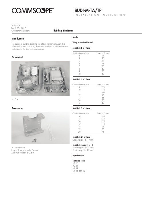
BUDI-M-TA/TPI N S T A L L A T I O N I N S T R U C T I O NBuilding distributorKit contentIntroductionThe Budi is a building distributor for a fiber managment system thatoffers the functions of splicing. Provides a mechanical and environmental protection for the fiber optic components.• BoxAccessories• Loop bracketLoop of 8 loose tubes (ø 2.4 mm).Maximum window of 2.6 m.SealsWrap around cable seals Sealblock 6 x 10 mm Cable diameter (mm) Foam (± 5 mm)3 954 905 806 757 708 609 50 10 40Sealblock 6 x 15 mm Cable diameter (mm) Foam (± 5 mm)9 125 10 115 11 105 12 95 13 85 14 70 15 60Sealblock 3 x 20 mm Cable diameter (mm) Foam (± 5 mm)14 155 15 140 16 125 17 110 18 95 19 85 20 75Sealblock 24 x 8 mm Cable range 1.8 – 7 mm Sealblock rubber 1 x 18To use in ports S6-S7 only Cable range 3 – 18 mm Pigtail seal 48Standard seals PG 16PG 21PG 29PG 29 (PTS 24)TC-1087-IPRev A, Mar 1.1 Different wrap-around ports are available (including brackets). Use two guiding pins to open the ports and to secure the bottom part tothe box. Cut out the plastic part if you want to install a cable.1.2Install the cable bracket depending the cable seal.1Preparation of the box 2.1Install the looped cable into the ports.2Looped feeder cable2.2Store the looped tubes into the loop bracket.2.3Route the loose tube towards the FAS block.3 Installation of the feeder cable3.1 Install the PG21 into the port.3.2Install the cable bracket into the box..3.3Prepare the feeder cable and insert the cable into the box.3.4 Install the cable onto the bracket, secure with hook and loop fastener and secure the aramid yarns if needed.3.5 Route the unused loose tubes towards the loop bracket for storage. Secure with te-wraps when needed.3.6 Route the loose tube towards the tube holder and strip.4Fiber routing4.1 Secure the wraparound groove plate on the UMS by putting the plate with the long protrusions in the S1 UMS-profile and sliding the plate in the S2 UMS-profile until it snaps. (Do not leave gaps between groove plates).S1S24.2 To remove push the two snapfits at S2 UMS-profile and slidethe wraparound plate towards S1 UMS-profile.4.4 Place a tray in the wraparound groove plate; do this by pushing the lip on the groove plate (lowest possible position) slightly down with the tray and move the tray lateral into the hinge-cavities of the groove plate. To snap the High Capacity Single Element tray (HCSE) in the W/a single fiber groove plate leave always one hinge facility open between Fasblock or previous tray and the HCSE-tray.4.5 To remove the tray put the fiber guiding pin between lip onwraparound groove plate and tray and move lateral towards S1.4.3 If box is not completely filled with groove plates, use pigtail clip retainer to hold the pigtails in place in the open area.4.7 Pull gently on the fibers in the tray and make sure that the fibers are well contained in the routing block and wraparound groove plate.4.6 Position the wedge carefully such that the groove is stillaccessible for the fibers and be careful not to push the wedge against fibers. To remove the wedge,use two hands to pull on both ends (near the groove plate). Route the fiber in the grooves of the wraparound groove plates to the entrance of the identified tray. Fiber must be routedin the groove below the hinge of the tray!4.8 Store the fibers temporarily on a tray (picture shows the case of a loopback).4.9 Storing dark fibers can be done in different ways.1) Organise dark fibers into the different trays, following instructions as described.2) Organise dark fibers together into the first available tray (i.e. with amax. of 24cut or 12 loops primary coated fibers in one SE-tray).5 Trays5.1 SMOUV in SC tray.5.2ANT in SE tray.5.3 ANT in SC tray.6 Patch panel TA/TP5.4 RECORDsplice in SC tray.5.5 RECORDsplice in SE tray.5.6 RECORDsplice/ANT in SC tray.5.7 Ribbon 4/8 tray.6.1 Slide the patch panel upwards up till the first locking position,not further.5.8 Ribbon 12 tray.5.9 Use a permanent marker to write on the tray.TATP6.2 Install the pigtails into the designated adaptors.TPTATATP7Connecting customers7.1 Slide the patch panel upwards until the first locking position, not futher. Connect the pigtail/patch cord into the designated adaptor.7.2 Once the top row of pigtails is installed, the pigtails can be routed towards the pigtail seal. Insert one by one into the groove.7.3Top rows can be installed in the first groove.6.3 Route the pigtails towards the tube holder, different grooves can be used to separate the bundle of pigtails if needed.TATP8Closing the box7.4 Bottom can be installed second groove.8.1Close the FAS block with the cover.8.2 Close the last tray with the cover and secure the trays with the hook and loop fastener.8.3 Closing the box.TATP© 2017 CommScope, Inc. All rights reserved. RECORDsplice, SMOUV and all trademarks identified by ® or ™ are registered trademarks or trademarks, respectively, of CommScope, Inc.This document is for planning purposes only and is not intended to modify or supplement any specifications or warranties relating toCommScope products or services.This product is covered by one or more U.S. patents or their foreign equivalents. For patents, see: /ProductPatent/ProductPatent.aspx.To find out more about CommScope® products, visit us on theweb at For technical assistance, customer service, or to report anymissing/damaged parts, visit us at:/SupportCenter。
红杉表Topu伯quick安装指南说明书

PERFORMANCE SERIES IP H4W2PER3*/H4W4PER3*/H4W8PER1* WDR IR Dome CameraQuick Installation Guide(The last “*” represents V or L, and other numbers or letters) Thank you for purchasing a Honeywell Performance Series IP camera. Follow the instructions in this guide to install and log in to your camera. For instructions on configuring the camera, refer to the user guide on the DVD that came with your camera. If you require additional assistance, call the number listed for your region on the back cover.WARNING To ensure compliance with electrical safety standards, this product isintended for use with a Listed Power Adapter marked “Limited Power Source” or “LPS” on the unit, output rated to 12 VDC, minimum 0.33 A, TMA=60 deg C, or from Power over Ethernet (PoE) provided by Listed Information Technology Equipment meeting IEEE 802.3af PoE standard.CAUTION The Ethernet connection is not intended to be connected to exposed(outside plant) networks. Do not connect two power sources to the camera at the same time.CAUTION Invisible LED radiation (850 nm). Avoid exposure to beam.Important Safeguards•Read and keep these instructions.•Confirm the installation surface can support at least three times the weight of the camera.•Do not aim the camera toward a bright light source for extended periods to prevent damage to the imager.•Avoid operating the unit under or close to unstable light sources (may cause flickering), or close to fluorescent lamps or objects reflecting light. •Do not touch the camera lens.•Do not drop the camera or subject it to physical shock.•Do not use a strong or abrasive detergent when cleaning the camera.•Avoid operating or storing the unit in extremely humid, dusty, hot/cold environments, where the operating temperature is outside the recommended range of -22°F to 140°F (–30°C to 60°C).•Do not apply power to the camera before completing installation.Before You BeginBefore you begin, check that you have received all of the parts listed below. If any parts are missing or damaged, contact your dealer immediately. •Camera•Installation DVD•Quick Installation Guide •Allen Key (L-wrench)•Self-tapping Screws (×4) •Plastic Wall Anchors (×4)•Mounting TemplateCAUTION Installation and servicing should be performed only by qualified and experienced technicians to conform to all local codes and to maintain your warranty.Preparing the Mounting Surface1.Apply the mounting template to the mounting surface.Note Observe the orientation of the cable exit notch on the bracket base. In outdoor installations, the notch should point downward to prevent water from entering the camera housing.ing the mounting template as a guide, drill three pilot holes in the mounting surface, then hammer the supplied anchors into the holes.3.Drill a cable entry hole in the mounting surface, then pull the required cables through the hole.Mounting and Aiming the Camera1.Remove the dome cover from the camera assembly using the supplied Allen k ey.2.If you are using a microSD card with the camera, install it before continuing. See below for details.1. Push and slide metal shell to unlock position.2. Openmetal shell.3. Insert microSDcard.4. Close metalshell and slide tolock position.3.Connect the Ethernet cable to the RJ-45 port on the c amera.4.If the other end of the Ethernet cable is not connected to a PoE (Power-over-Ethernet)switch or NVR, connect the power connector of the camera to a 12 VDC power source.5.Fix the camera assembly to the mounting surface using the supplied screws.6.Aim the camera lens in the desired direction, then tighten the screws on the cameraassembly.7.Reattach the dome cover.Logging On to the CameraIf the camera is connected to the PoE port of a Honeywell Embedded NVR, it can be configured using the NVR.To log on remotely from a PC, install the Unified Tool from the software and documentation DVD, find the camera on the network, and then open the web browser. The default user name is admin (case-sensitive) and the default password is 1234.Note •Only Internet Explorer 11 (or later) is supported.•IP address of the device is assigned automatically by DHCP server. If the DHCPserver is not available, the device will acquire192.168.1.108 as the default IPaddress.Recommended RecordersHEN*4 8/16/32/64-channel Focus 4K NVRs (H.264 and H.265)HEN*3 4/8/16/32-channel Performance Series NVRs (H.264 and H.265) Regulatory StatementsFCC ComplianceThis equipment has been tested and found to comply with the limits for a Class B digital device, pursuant to part 15 of the FCC Rules. These limits are designed to provide reasonable protection against harmful interference in a residential installation. This equipment generates, uses, and can radiate radio frequency energy and, if not installed and used in accordance with the instructions, may cause harmful interference to radio communications. However, there is no guarantee that interference will not occur in a particular installation.If this equipment does cause harmful interference to radio or television reception, which can be determined by turning the equipment off and on, the user is encouraged to try to correct the interference by one or more of the following measures:•Reorient or relocate the receiving antenna.•Increase the separation between the equipment and receiver.•Connect the equipment into an outlet on a circuit different from that to which the receiver is connected.•Consult the dealer or an experienced radio/TV technician for help.Note Changes or modifications not expressly approved by the party responsible for compliance could void the user’s authority to operate the equipment.This Class B digital apparatus complies with Canadian ICES-003.Manufacturer’s Declaration of ConformanceNorth America The equipment supplied with this guide conforms to UL 60950-1 and CSA C22.2 No. 60950-1.Europe The manufacturer declares that the equipment supplied is compliant with the European Parliament and Council Directive on the restriction of the use of certain hazardous substances in electrical and electronic equipment (2015/863/EU), the Low Voltage Directive (2014/35/EU) and the essential requirements of the EMC directive (2014/30/EU), conforming to the requirements of standards EN 55032 for emissions, EN 50130-4 for immunity, and EN 62368-1 for electrical equipment safety.WEEE (Waste Electrical and Electronic Equipment)Correct disposal of this product (applicable in the European Union and otherEuropean countries with separate collection systems). This product should bedisposed of, at the end of its useful life, as per applicable local laws, regulations,and procedures.North America Europe Middle East 715 Peachtree St. NE Atlanta,GA 30308Newhouse Industrial EstateMotherwell Lanarkshire ML1 5SBUnited KingdomEmaar Business Park, Building No. 2,Sheikh Zayed RoadP.O. Box 232362 Dubai, United Arab EmiratesTel:180****4576/ukTel: +44 (0) 1928 378005/meTel: +971 4 450 5800 Document 800-26629-A, 03/2021© 2021 Honeywell International Inc. All rights reserved. No part of this publication may be reproduced by any means without written permission from Honeywell. The information in this publication is believed to be accurate in all respects. However, Honeywell cannot assume responsibility for any consequences resulting from the use thereof. The information contained herein is subject to change without notice. Revisions or new additions to this publication may be issued to incorporate such changes.。
TIBCO OpenSpirit Extension for ArcGIS 安装指南说明书

TIBCO OpenSpirit®Extension for ArcGIS Installation GuideArcMap Desktop Add-In Software Release 2019.0.0September 2019Important InformationSOME TIBCO SOFTWARE EMBEDS OR BUNDLES OTHER TIBCO SOFTWARE. USE OF SUCH EMBEDDED OR BUNDLED TIBCO SOFTWARE IS SOLELY TO ENABLE THE FUNCTIONALITY (OR PROVIDE LIMITED ADD-ON FUNCTIONALITY) OF THE LICENSED TIBCO SOFTWARE. THE EMBEDDED OR BUNDLED SOFTWARE IS NOT LICENSED TO BE USED OR ACCESSED BY ANY OTHER TIBCO SOFTWARE OR FOR ANY OTHER PURPOSE. USE OF TIBCO SOFTWARE AND THIS DOCUMENTIS SUBJECT TO THE TERMS AND CONDITIONS OF A LICENSE AGREEMENT FOUND IN EITHER A SEPARATELY EXECUTED SOFTWARE LICENSE AGREEMENT, OR, IF THERE IS NO SUCH SEPARATE AGREEMENT, THE CLICKWRAP END USER LICENSE AGREEMENT WHICH IS DISPLAYED DURING DOWNLOAD OR INSTALLATION OF THE SOFTWARE (AND WHICH IS DUPLICATED IN THE LICENSE FILE) OR IF THERE IS NO SUCH SOFTWARE LICENSE AGREEMENT OR CLICKWRAP END USER LICENSE AGREEMENT, THE LICENSE(S) LOCATED IN THE “LICENSE” FILE(S) OF THE SOFTWARE. USE OF THIS DOCUMENT IS SUBJECT TO THOSE TERMS AND CONDITIONS, AND YOUR USE HEREOF SHALL CONSTITUTE ACCEPTANCE OF AND AN AGREEMENT TO BE BOUND BY THE SAME. This document contains confidential information that is subject to U.S. and international copyright laws and treaties. No part of this document may be reproduced in any form without the written authorization of TIBCO Software Inc. TIBCO, OpenSpirit, and TIBCO OpenSpirit Extension for ArcGIS are either registered trademarks or trademarks of TIBCO Software Inc. in the United States and/or other countries.All other product and company names and marks mentioned in this document are the property of their respective owners and are mentioned for identification purposes only.THIS SOFTWARE MAY BE AVAILABLE ON MULTIPLE OPERATING SYSTEMS. HOWEVER, NOT ALL OPERATING SYSTEM PLATFORMS FOR A SPECIFIC SOFTWARE VERSION ARE RELEASED AT THE SAME TIME. SEE THE RELEASE NOTES FOR THE AVAILABILITY OF THIS SOFTWARE VERSIONON A SPECIFIC OPERATING SYSTEM PLATFORM.THIS DOCUMENT IS PROVIDED “AS IS” WITHOUT WARRANTY OF ANY KIND, EITHER EXPRESS OR IMPLIED, INCLUDING, BUT NOT LIMITED TO, THE IMPLIED WARRANTIES OF MERCHANTABILITY, FITNESS FOR A PARTICULAR PURPOSE, OR NON-INFRINGEMENT.THIS DOCUMENT COULD INCLUDE TECHNICAL INACCURACIES OR TYPOGRAPHICAL ERRORS. CHANGES ARE PERIODICALLY ADDED TO THE INFORMATION HEREIN; THESE CHANGES WILL BE INCORPORATED IN NEW EDITIONS OF THIS DOCUMENT. TIBCO SOFTWARE INC. MAY MAKE IMPROVEMENTS AND/OR CHANGES IN THE PRODUCT(S) AND/OR THE PROGRAM(S) DESCRIBED IN THIS DOCUMENT AT ANY TIME. THE CONTENTS OF THIS DOCUMENT MAY BE MODIFIED AND/OR QUALIFIED, DIRECTLY OR INDIRECTLY, BY OTHER DOCUMENTATION WHICH ACCOMPANIES THIS SOFTWARE, INCLUDING BUT NOT LIMITED TO ANY RELEASE NOTES AND "READ ME" FILES.Copyright © 2002-2019 TIBCO Software Inc. ALL RIGHTS RESERVED.TIBCO Software Inc. Confidential InformationiiiTable of ContentsOverview (4)Installation (6)Prerequisites (6)Installation Steps (6)Uninstall Steps (13)OverviewWith the OpenSpirit Extension, a user can extend ArcGIS functionality to allow a user to browse well, seismic, and interpretation data coming from a variety of G&G data stores and to bi-directionally share interaction events with other OpenSpirit enabled applications. Specifically this extension adds the ability to connect ArcMap to OpenSpirit in order to: •Read well, seismic, and interpretation data from OpenSpirit enabled data stores anddisplay in ArcMap•Send and receive OpenSpirit data selection events (exchange references to data with other applications)•Send and receive OpenSpirit GIS events (exchange point, polyline and polygon features with other applications)•Send and receive OpenSpirit grid events (exchange surface grids with other applications)•Send and receive OpenSpirit cursor tracking events (exchange mouse cursor x,y,z positions with other applications)•Send and receive OpenSpirit map view events (synchronize map view extents with other applications)•Send OpenSpirit map image events (synchronize map view extents with other applications and display an image of the map)•Establish a selection highlighting synchronization session (send and receive instructions to select features)InstallationPrerequisitesIn order to use the TIBCO OpenSpirit Extension for ArcGIS you must have the following applications installed on your Windows PC (running Windows 7, or Windows 10): •ArcGIS Desktop (ArcView or ArcEdit license) version 10.6 or 10.7.•OpenSpirit Runtime version 4.2.0 w/ Runtime HotFix 06 or OpenSpirit Runtime4.3.0 Installation StepsInstallation StepsThe TIBCO OpenSpirit Extension for ArcGIS is delivered as an ArcGIS Desktop Add-In.1.Download the OpenSpirit.ArcMapExtension.UI.esriAddIn file to a convenientlocation on your PC.2.Make sure the file is not blocked by right clicking on the .esriAddin file and selectingthe Unblock option if it is present.3.Install the Extension by double-clicking on the esriAddin file. This will display theESRI Add-In Utility:Then click on "Install Add-In".Your company may choose to install add-ins from a shared network drive, in which case you may just put the OpenSpirit Add-In in this directory and ArcGIS willdiscover it the next time it is run.4.Create a Windows firewall exemption rule for the ArcMap executable to enable theOpenSpirit extension to receive events.Open a Windows command window or a power shell window with administrator privilege and execute the command:netsh.exe firewall add allowedprogram program="C:\Program Files (x86)\ArcGIS\<version>\bin\ArcMap.exe" name="ArcMap"mode=ENABLE scope=ALL profile=ALLwhere <version> is the version of ArcGIS Desktop you have installed.For example, if running with ArcGIS Desktop 10.5 installed in the default location:: netsh.exe firewall add allowedprogram program="C:\ProgramFiles (x86)\ArcGIS\Desktop10.5\bin\ArcMap.exe"name="ArcMap" mode=ENABLE scope=ALL profile=ALLunch ArcGIS Desktop6.If the OpenSpirit toolbar is not visible make sure it is enabled for display bynavigating to the Customize-> Extensions menu item and make sure the toolbar isenabled for display. It should look like this:Check your ArcGIS Add-In Manager options if the OpenSpirit toolbar does not appear in the list of extensions. ArcGIS will not load the OpenSpirit Extension if the Load only ESRI provided Add-Ins option is selected on the Add-In Manager's Options tab. Use the Require Add-Ins to be digitally signed by a trusted publisher option or the Load all Add-Inswithout restrictions option. ArcMap must be restarted for the OpenSpirit Extension to appear in the extension list after changing the setting.7.The OpenSpirit toolbar should appear as a dockable toolbar like this:In order to dock it simply drag it by it's light blue header and deposit it on the arrow icon indicating where you want the toolbar docked:Toolbar docked at North of map window:Uninstall StepsThe TIBCO OpenSpirit Extension for ArcGIS is uninstalled using the ArcMap Add-In Manager. In the ArcMap menu select Customize>Add-in Manager... menu item. The Add-in Manager window will open, under the My Add-ins section, select the TIBCO OpenSpirit Extension for ArcGIS entry, finally click the Delete this Add-in button. This will uninstall the add-in.。
TIBCO安装图示
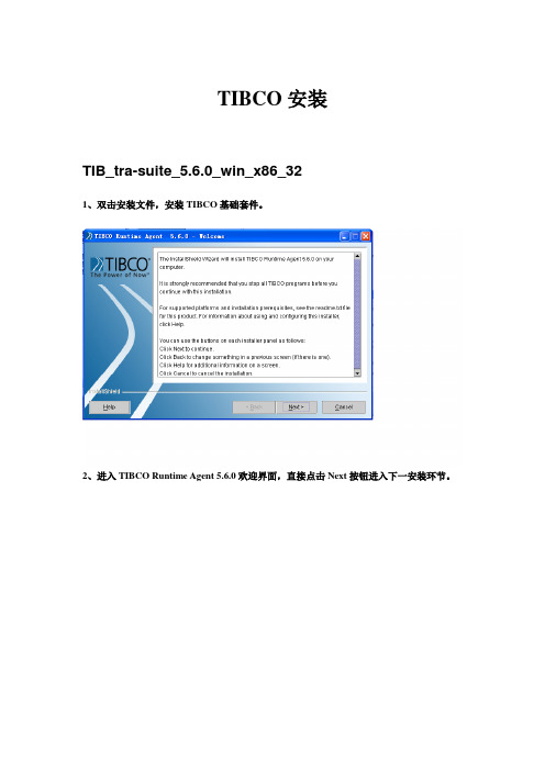
TIBCO安装TIB_tra-suite_5.6.0_win_x86_321、双击安装文件,安装TIBCO基础套件。
2、进入TIBCO Runtime Agent 5.6.0欢迎界面,直接点击Next按钮进入下一安装环节。
议的单选框),选中接受许可协议,然后点击Next进入下一安装环节。
4、进入通知界面,直接点击Next进入下一安装环节。
定义安装路径),然后点击Next按钮进入下一安装环节。
Next按钮进入下一安装环节。
击Next进入下一安装环节。
Next进入下一安装环节。
Next进入下一安装环节。
10、进入安装信息预览界面,浏览安装信息,确认无误后点击Next按钮进入下一安装环节。
进入下一安装环节。
12、进入安装概要信息界面,浏览安装概要,确认无误后点击Finish按钮完成套件安装。
TIB_tra-suite_5.6.2_win_x861、双击安装文件,进入TIBCO Runtime Agent 5.6.2安装界面。
2、进去TIBCO Runtime Agent 5.6.2安装欢迎界面,直接点击Next按钮进入下一安装环节。
议的单选框),选中接受许可协议,然后点击Next进入下一安装环节。
4、进入通知界面,直接点击Next进入下一安装环节。
进入下一安装环节。
Next按钮进入下一安装环节。
7、弹出是否升级的提示框,直接点击YES按钮。
8、进入JAV A运行环境升级界面,点击Next进入下一安装环节。
9、进入安装信息预览界面,浏览安装信息,确认无误后点击Next按钮进入下一安装环节。
10、进入安装概要信息界面,浏览安装概要,确认无误后点击Finish按钮完成Runtime Agent5.6.2安装。
TIB_ems_6.0.0_win_x86_vc81、双击安装文件,安装EMS6.0.02、进入EMS安装欢迎界面,直接点击Next按钮进入下一安装环节。
3、进入安装许可协议界面,勾选接受安装许可协议,然后点击Next进入下一安装环节。
Carbide3D BitSetter自动工具偏移探测器安装和设置指南说明书
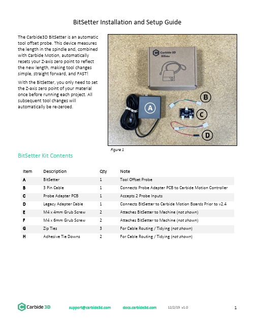
BitSetter Installation and Setup GuideThe Carbide3D BitSetter is an automatictool offset probe. This device measuresthe length in the spindle and, combinedwith Carbide Motion, automaticallyresets your Z-axis zero point to reflectthe new length, making tool changessimple, straight forward, and FAST!With the BitSetter, you only need to setthe Z-axis zero point of your materialonce before running each project. Allsubsequent tool changes willautomatically be re-zeroed.BitSetter Kit ContentsItemDescription Qty Note ABitSetter 1 Tool Offset Probe B3 Pin Cable 1 Connects Probe Adapter PCB to Carbide Motion Controller CProbe Adapter PCB 1 Accepts 2 Probe Inputs DLegacy Adapter Cable 1 Connects BitSetter to Carbide Motion Boards Prior to v2.4 EM4 x 4mm Grub Screw 2 Attaches BitSetter to Machine (not shown ) FM4 x 6mm Grub Screw 2 Attaches BitSetter to Machine (not shown ) GZip Ties 3 For Cable Routing / Tidying (not shown ) HAdhesive Tie Downs2 For Cable Routing / Tidying (not shown )Figure 1Install the BitSetterShapeoko XL/XXL InstallationThe BitSetter attaches to the front of your Shapeoko by sliding over the lip of the front end plate. The unit is secured to the machine with grub screws inserted from the rear of the BitSetter. See Figure 2. 1. Turn off your machine and unplug it. Disconnect the USB cable.2. Insert M4x4mm grub screws into the toptwo screw holes (shown in Figure 3). Juststart the screws so they are barely in thethreads.3. Slide the BitSetter over the edge of the frontend plate, about 4.5 inches (115mm) fromthe right edge of the end plate See Figure 4.4. To make sure the spindle can touch theBitSetter without interference, slowly movethe gantry (by hand) so it is directly abovethe BitSetter. Ensure the center of thespindle is in line with the center of theBitSetter. See Figure 7 below. 5. If necessary, slide your BitSetter to the rightor left along the front end plate to align the trigger with the center of your spindle.6. Once aligned, tighten the two M4x4mm screws so they press into the rail. These need only be snug,do not overtighten!NOTE: If you would prefer your BitSetter to sit higher in the Z direction, you can also install the BitSetter per the Shapeoko 3 installation instructions (see next page).Figure 3Figure 4Figure 2Shapeoko 3 InstallationThe BitSetter attaches to the front of your Shapeoko by sliding over the lip of the front end plate. The unit is secured to the machine with grub screws inserted from the rear of the BitSetter. See Figure 5.1. Turn off your machine and unplug it. Disconnect the USB cable.2. Insert two M4x6mm screws into the middle row of holes. See Figure 6.3. Tighten the screws until they hit the back wall of the BitSetter. These screws will raise your BitSetterup so that it does not rest on the worktable.4. Insert the two M4x4mm screws into the bottom holes;do not tighten them yet. See Figure 5.5. Slide the BitSetter over the lip of the front end plate,about 4.5 inches (115mm) from the right edge of theend plate.6. To make sure the spindle can touch the BitSetterwithout interference, slowly move your gantry (byhand) so it is above the BitSetter. Ensure the center ofthe spindle is in line with the center of the BitSetter.See Figure 7.7. If necessary, slide your BitSetter to the right or leftalong the front end plate to align the trigger with thecenter of your spindle.8. Once aligned, tighten the bottom two M4x4mm screws so they press into the end plate. These needonly be snug, do not overtighten!NOTE: If you are using the stock wasteboard, you can access the bottom screws using a ball-end hex key. If using additional wasteboards, you may need to remove the wasteboard to access the screws.Figure 7 Figure 6Figure 5Route the CableThe BitSetter cable is designed to route to your Carbide Motion controller one of two ways.Routing Option 1ing the cutout on the bottom of the BitSetter, route the cable under the machine, directly back tothe controller.e the included adhesive tie downs and zip ties to secure the cable to the machine. We recommendone tie down immediately behind the BitSetter and another where the wire feeds out near thecontroller.Routing Option 2ing the cutout on the bottom of the BitSetter, route the cable around the front-left side of themachine.e the included adhesive tie downs and zip ties to secure the cable to your machine. Make sure thecable is out of the way and fastened to your machine in convenient locations.Connect the BitSetter to the Controller BoardTo make installation simple, we have included a variety of adapters to allow you to connect the BitSetter without needing to cut or solder any wires.The instructions below apply to versions of the Carbide Motion boards shipped with Shapeoko:- 2.1 - 2.2- 2.3- 2.4d- 2.4eTo identify which version of the Carbide Motion board you own, look in the bottom-left corner of the PCB.Figure 8Version 2.1/2.2/2.3 (Using the Legacy Adapter Cable)1.Connect the female connector (green and white wires) to the probe pins as shown in Figure 9.2.Connect the red wire (+5V) to the upper-leftpin on the AVR PROGRAMMING label asshown in Figure 10.3.Once both wires are plugged in, your boardshould look like Figure 11.4.Connect the Legacy Adapter Cable to the portlabeled TO CARBIDE MOTION on the ProbeAdapter PCB.5.Connect the BitSetter to the port labeledTOOL PROBE on the Probe Adapter PCB.NOTE: If you also have a Carbide 3D probe, plug that into the port labeled TOUCH PROBE on the Probe Adapter PCB.Figure 9Figure 10Figure 11Version 2.4Beginning with version 2.4d of the Carbide Motion Controller PCB, the controller boards have a purpose-built port labeled RESERVED, which is intended for a touch probe.1.Connect the BitSetter:a.If you only have the BitSetter, you can plug it directly into the port labeled RESERVED asshown in Figure 12.b.If you have both the BitSetter and a Touch Probe, use the Probe Adapter PCB as shown inFigure 13.NOTE: If your 2.4d/e board is missing theRESERVED2.After your cable is routed to the Carbide Motion Controller, re-install the controller cover orenclosure. Make sure not to pinch or accidentally loosen any of the cables.Figure 12 Figure 13Set Up and Calibrate Carbide MotionWith the hardware installed, you now need to setup Carbide Motion control software to recognize and calibrate your BitSetter.Connect to Shapeoko1.Open Carbide Motion.2.Power on the Shapeoko, then click the Connect to Cutter button . See Figure 14.3.After the software connects, click the Initialize Machine button. This will begin a homing cycle. SeeFigure 15.Figure 14 Figure 15Clear Offsets and Change to Machine CoordinatesClear Offsets1. After homing completes, click Jog in the top menu bar.2. Click the Set Zero button . See Figure 16.3. On the Set Current Position screen, click the Clear All Offsets button . Then, click DONE . See Figure 17.4. Click the Position label . This will toggle the view to the machine coordinates. See Figure 18.5.Click Rapid Position , then click the SE button to move thespindle to the front-right of the machine. Once in position, clickDONE . See Figure 18.6. From the JOG screen, use the arrows on the screen (or thearrows on your keyboard) to jog the gantry so the spindle isdirectly above the BitSetter (as shown in Figure 19).Figure 16 Figure 17Figure 18Figure 19Configure the Permanent Position of the BitSetterFigure 20 Figure 211.Click Settings in the top menu bar.2.Click the Setup Shapeoko button. See Figure 20.3.Select the appropriate size Shapeoko from the Size dropdown list (Shapeoko 3, XL, XXL). SeeFigure 21.4.Select the Use Shapeoko HDZ checkbox, if you are using an HDZ.5.Select the BitSetter Probe checkbox. This will expand the window and allow you to configure thepermanent location of the BitSetter.6.With your spindle directly above the BitSetter, click the Use Current X/Y button to set the location.This will permanently save the X/Y location of your BitSetter.NOTE: If you physically change the BitSetter location, you will need to re-run this setup.7.Click the Update Shapoeko Configuration button to save the settings. CONGRATULATIONS! Your BitSetter is ready to use!********************* 12/2/19 v1.011Operating Your BitsetterThe start-up workflow using the BitSetter is as follows:1. Power on and connect to machine.2. Initialize Machine – this will begin a homing cycle.3. After the homing cycle completes, the gantry will automatically move to the front-right location and prompt you to insert a tool. Think of this as ‘homing’ the tool off set.4. After the tool is inserted or confirmed, the machine will then measure the length of the tool in the spindle.5. Once the initialization sequence is complete, you can load and run a job by using the Load File feature.Notes About Using Your BitSetter• Ensure tools are long enough to reach the BitSetter trigger button. The minimum length the tool must extend from the collet is 0.5.”• In order to instantiate a tool change and offset measurement, your CAM program must post unique tool numbers with each new tool. Carbide Create does this by default.• If you ever physically move the BitSetter, you will need to reconfigure its new location by following these instructions again.Check Out the BitSetter Installation VideoThere is also a complimentary video to go along with these installation instructions, which can be viewed at: https://youtu.be/I97XwLBmyuc .。
- 1、下载文档前请自行甄别文档内容的完整性,平台不提供额外的编辑、内容补充、找答案等附加服务。
- 2、"仅部分预览"的文档,不可在线预览部分如存在完整性等问题,可反馈申请退款(可完整预览的文档不适用该条件!)。
- 3、如文档侵犯您的权益,请联系客服反馈,我们会尽快为您处理(人工客服工作时间:9:00-18:30)。
TIBCO产品安装手册目录1引言 (1)1.1编写目的 (1)1.2预期读者 (1)1.3术语 (1)1.4参考资料 (1)2产品概述 (3)2.1目标 (3)2.2运行环境 (3)2.3产品架构 (3)2.3.1项目TIBCO产品简介 (4)3产品安装 (6)3.1安装TIBCO R UNTIME A GENT (6)3.1.1前置条件 (6)3.1.2安装步骤 (6)3.2安装TIBCO EMS (9)3.2.1前置条件 (9)3.2.2安装步骤 (10)3.3安装TIBCO A DMINISTRATOR (13)3.3.1前置条件 (13)3.3.2安装步骤 (13)3.4安装TIBCO B USINESS WORKS (18)3.4.1前置条件 (18)3.4.2安装步骤 (19)3.5安装TIBCO A DAPTER FOR A CTIVE D ATABASE (22)3.5.1前置条件 (22)3.5.2安装步骤 (22)3.6安装TIBCO A DAPTER FOR L OTUS N OTES (25)3.6.1前置条件 (25)3.6.2安装步骤 (26)3.7安装TIBCO A DAPTER FOR F ILES (30)3.7.1前置条件 (30)3.7.2安装步骤 (30)3.8安装TIBCO A DAPTER FOR S WIFT (33)3.8.1前置条件 (33)3.8.2安装步骤 (33)3.9安装TIBCO IPROCESS E NGINE (36)3.9.1前置条件 (36)3.9.2安装步骤 (37)3.10安装TIBCO IPROCESS M ODELER (39)3.10.1前置条件 (39)3.10.2安装步骤 (39)4技术支持 ...................................................................................................... 错误!未定义书签。
4.1怎么联系TIBCO技术支持 ............................................................... 错误!未定义书签。
图目录图2-1TIBCO产品架构 (4)表格目录表1-1术语对照 (1)表1-2参考资料 (2)1引言1.1 编写目的为了项目的系统管理员和其他的技术支持人员能够顺利的安装TIBCO产品,并且更好的完成该项目的开发和维护工作,特编写《综合档案管理系统及与行内其他业务系统集成项目TIBCO产品安装手册》(以下简称产品安装手册)。
1.2 预期读者本文读者为应用集成平台的系统管理员和其他的技术支持人员,并且已具备UNIX, UNIX-shells 和Windows 2000 server操作系统的管理知识。
1.3 术语表1-1 术语对照1.4 参考资料表1-2 参考资料2产品概述2.1 目标详细描述项目中所有TIBCO 产品的安装过程,为项目管理员以及技术支持人员提供明确的安装说明,提高项目开发和维护的效率。
2.2 运行环境1、硬件环境2、软件环境系统需安装JDK1.4或更高版本的JA V A环境,此外还需安装TOMCAT4或更高版本。
2.3 产品架构下图所展示的是TIBCO 产品的架构及相互关系:图2-1 TIBCO产品架构2.3.1项目TIBCO产品简介TIBCO Runtime Agent: TIBCO Runtime Agent 即 TRA 是TIBCO所有产品的基础平台. TRA 由 TIBCO Rendezvous, TIBCO Designer 以及第三方组件库构成。
TIBCO Rendezvous 是一个基于消息的中间件,它提供了多样化的消息发送与接收方式,如:可靠模式, 鉴定模式,应答模式等等. 这些多样的消息传输方式可以根据应用的需要进行选择使用.所有集成平台中的应用程序都是通过 TIBCO Rendezvous 来进行相互通讯的。
TIBCO Business works: TIBCO Business works 及BW 是由一个基于图形界面的设计工具和一个流程引擎所组成. 使用BW所提供的图形化设计工具能够非常简单快速地设计、开发业务流程,然后部署到流程引擎中自动运行。
Business works 还支持在TIBCO产品之间进行消息映射和传输的连接方式。
TIBCO Administrator: TIBCO Administrator 是一个和TRA合作使用的管理组件. TIBCO Administrator提供了用户管理和商业应用流程管理。
通过TIBCOAdministrator用户可以轻松的进行商业流程的上传,部署,配置,监控和卸载。
TIBCO EMS:TIBCO Enterprise Message Service™ 即EMS是TIBCO对SUN 的Java Message Service (JMS) protocol的具体实现,也是一个基于标准的消息中间件,它除了实现JMS之外,还可以同TIBCO Rendezvous 之间进行消息通讯,这样为用户在消息传输方面提供了更多的选择。
TIBCO Adapter for ActiveDatabase:TIBCO Adapter for ActiveDatabase 是一个用来监控数据库中数据变化的软件。
它把发布/订阅与请求/回复机制扩充到数据库层面,使数据库应用可以使用多种不同层次的消息传递服务,当数据库中的数据发生变化的时候,TIBCO Adapter for ActiveDatabase 会将这些变化的数据以消息的方式发送给TIBCO集成平台,由平台再触发响应的业务流程。
它是用TIBCO 适配器开发包开发而成,所以可以同其他的基于TIBCO产品的应用进行交互。
它支持所有的ODBC兼容数据库,包括DB2, Oracle, Sybase, Informix, Microsoft SQL Server, TimesTen in-memory database等。
TIBCO Adapter for Lotus Notes: TIBCO Adapter for Lotus Notes 是Lotus Notes应用同TIBCO平台上配置的应用之间的双向的网关,它基于消息中间件产品TIBCO Rendezvous处理Lotus Notes模式及结构,实现实时的应用互联,可以同TIBCO 平台所连接的企业应用完成无缝的连接。
TIBCO Adapter for Files: TIBCO Adapter for Files 是一个可以对文件进行监控,并实时地将文件中的内容发布到TIBCO应用集成环境的产品。
不仅如此,它同样能够监听来自TIBCO应用集成环境的信息,并可以将信息写到文件中。
TIBCO Adapter for Swift: TIBCO Adapter for Swift产品是金融机构完整的端到端解决方案的重要组成部分,用以通过SWIFT消息网络实现交易结算操作,在金融机构同他们的客户以及合作伙伴之间收发消息。
通过TIBCO Adapter for SWIFT 可以实现SWIFT网络的SWIFT消息的收发应用,TIBCO支持多种的同SWIFT网络间的连接技术接口,包括:TCP/IP方式;消息中间件方式;FTP方式等。
TIBCO iprocess Engine: TIBCO iprocess Engine是一个工作流引擎,它为TIBCOBusiness Process Management架构提供了一整套的解决方案,所有开发完成的工作流都将运行在TIBCO iprocess Engine中,以便实现工作流的启动,调用,挂起,终止。
TIBCO iprocess Modeler: TIBCO iprocess Modeler是一个工作流程的开发环境,用户可以利用TIBCO iprocess Modeler进行工作流的开发、调试、部署,不仅如此,它还提供了很多插件功能,用于跟踪,仿真,分析工作流,从而提高工作流设计的合理性以及性能。
3产品安装3.1 安装TIBCO Runtime Agent3.1.1前置条件TBICO Runtime Agent所支持的操作系统:∙Microsoft Windows Server 2003 on x86 with Service Pack 1∙Microsoft Windows XP on x86 with Service Pack 1 or 2∙Microsoft Windows 2000 on x86 with Service Pack 2∙AIX 5.3 on POWER∙AIX 5.2 on POWER with patch 5300-04∙HP-UX 11i v2/11.23 on IA-64/Itanium∙HP-UX 11i/11.11 on PA-RISC∙所有HP-UX 平台必须安装J2SE 包: /products1/unix/java/patches/index.html ∙Linux Kernel 2.4, glibc 2.2 on x86∙Linux Kernel 2.4, glibc 2.3 on x86∙Linux Kernel 2.6, glibc 2.3 on x86∙Solaris 10 on SPARC∙Solaris 10 on x86∙Solaris 9 on SPARC∙Solaris 8 on SPARC with patches 109742-04 109279-183.1.2安装步骤1)双击TRA安装文件进入TIBCO产品安装界面,下一步2)选择接受协议,下一步3)直接下一步4)选择典型安装,下一步5)指定安装路径,下一步6)直接下一步7)开始安装8)安装完成3.2 安装TIBCO EMS3.2.1前置条件TBICO Runtime EMS所支持的操作系统:∙Microsoft Windows Server 2003 on x86 with Service Pack 1∙Microsoft Windows XP on x86 with Service Pack 1 or 2∙Microsoft Windows 2000 on x86 with Service Pack 2∙AIX 5.3 on POWER∙AIX 5.2 on POWER with patch 5300-04∙HP-UX 11i v2/11.23 on IA-64/Itanium∙HP-UX 11i/11.11 on PA-RISC∙所有HP-UX 平台必须安装J2SE 包: /products1/unix/java/patches/index.html∙Linux Kernel 2.4, glibc 2.2 on x86∙Linux Kernel 2.4, glibc 2.3 on x86∙Linux Kernel 2.6, glibc 2.3 on x86∙Solaris 10 on SPARC∙Solaris 10 on x86∙Solaris 9 on SPARC∙Solaris 8 on SPARC with patches 109742-04 109279-183.2.2安装步骤1)双击EMS安装文件进入TIBCO产品安装界面,下一步2)选择接受协议,下一步3)选择安装路径,下一步4)选择典型安装,下一步5)选择EMS服务自动启动,下一步6)察看安装信息,下一步7)开始安装8)安装成功3.3 安装TIBCO Administrator3.3.1前置条件需要预先安装的TIBCO产品:TIBCO Runtime AgentTIBCO Enterprise for JMS(可选)3.3.2安装步骤1)双击Administrator安装文件进入TIBCO产品安装界面,下一步2)接受协议,下一步3)下一步4)默认安装,下一步5)选择典型安装,下一步6)直接下一步7)开始安装8)安装成功,选择下一步,进行Administrator服务配置9)选择Master,下一步10)填写domain名称,其它默认,下一步11)默认,下一步12)输入要创建的用户名密码,下一步13)下一步14)下一步15)配置Administrator 服务完成,Administrator安装全部结束3.4 安装TIBCO Business works3.4.1前置条件需要预先安装的TIBCO产品:TIBCO Runtime AgentTIBCO DesignerTIBCO AdministratorTIBCO Enterprise for JMS(可选)3.4.2安装步骤1)双击TIBCO Business works安装文件进入TIBCO产品安装界面,下一步2)接受协议,下一步3)下一步4)默认,下一步5)选择典型安装,下一步6)下一步7)开始安装8)安装成功3.5 安装TIBCO Adapter for ActiveDatabase3.5.1前置条件需要预先安装的TIBCO产品:TIBCO Runtime AgentTIBCO DesignerTIBCO AdministratorTIBCO Enterprise for JMS(可选)3.5.2安装步骤1)双击ActiveDatabase安装文件进入TIBCO产品安装界面,下一步2)接受协议,下一步3)下一步4)默认,下一步5)选择典型安装,下一步6)下一步7)开始安装8)安装成功3.6 安装TIBCO Adapter for Lotus Notes 3.6.1前置条件需要预先安装的TIBCO产品:TIBCO Runtime AgentTIBCO DesignerTIBCO AdministratorTIBCO Enterprise for JMS(可选)此外,还需安装Lotus Notes应用程序,否则不能安装TIBCO Adapter for Lotus Notes。