
思科入门级基本试验
基本实验路由器基本操作1.Router> //用户模式Router>enable //在用户模式敲入enable 进入特权模式(也叫enable 模式)Router#disable //在特权模式敲入disable 退出到用户模式Router>enable //在用户模式敲入enable 进入特权模式Router#configure terminal //在特权模式敲入configure terminal 进入到配置模式Router(config)#interface ethernet 0/0 //在配置模式敲入“interface+接口类型+接口编号”进入接口模式Router(config-if)#exit //敲入exit 退出接口模式Router(config)#router rip //敲入“router + 路由协议”进入router 模式Router(config-router)#exit //退出router 模式Router(config)#line console 0 //进入line 模式Router(config-line)#end //从line 模式退出(任何时候敲入end 会退出到特权模式)Router#conf tRouter(config)#interface ethernet 0/0.1 //进入子接口模式Router(config-subif)#end //任何时候敲入end 会退出到特权模式常用show命令的介绍:Router#show version 查看路由器版本Router#show flash: 查看路由器flashRouter#show history 查看历史命令记录Router#show interfaces s0/0 查看接口物理相关信息Router#show ip int s0/0 查看接口协议相关信息Router#show ip int brief 查看接口简要信息Router#show running-config 查看路由器启动配置文件Router#show running-config 查看路由器运行配置文件Router#show users 查看当前登录的所有用户Router#show arp 查看路由器ARP表试验如下图:查看路由器日志信息:Router#show buffersBuffer elements:1119 in free list (1119 max allowed)16 hits, 0 misses, 619 createdPublic buffer pools:Small buffers, 104 bytes (total 89, permanent 50, peak 89 @ 00:01:08): 58 in free list (20 min, 150 max allowed)97 hits, 13 misses, 0 trims, 39 created0 failures (0 no memory)Middle buffers, 600 bytes (total 43, permanent 25, peak 43 @ 00:01:09): 40 in free list (10 min, 150 max allowed)92 hits, 6 misses, 0 trims, 18 created0 failures (0 no memory)Big buffers, 1536 bytes (total 50, permanent 50):50 in free list (5 min, 150 max allowed)66 hits, 0 misses, 0 trims, 0 created0 failures (0 no memory)VeryBig buffers, 4520 bytes (total 10, permanent 10):10 in free list (0 min, 100 max allowed)0 hits, 0 misses, 0 trims, 0 created0 failures (0 no memory)Large buffers, 5024 bytes (total 0, permanent 0):0 in free list (0 min, 10 max allowed)0 hits, 0 misses, 0 trims, 0 created0 failures (0 no memory)Huge buffers, 18024 bytes (total 0, permanent 0):0 in free list (0 min, 4 max allowed)0 hits, 0 misses, 0 trims, 0 created0 failures (0 no memory)Interface buffer pools:IPC buffers, 4096 bytes (total 2, permanent 2):2 in free list (1 min, 8 max allowed)0 hits, 0 fallbacks, 0 trims, 0 created0 failures (0 no memory)Header pools:Header buffers, 0 bytes (total 511, permanent 256, peak 511 @ 00:01:19): 255 in free list (256 min, 1024 max allowed)171 hits, 85 misses, 0 trims, 255 created0 failures (0 no memory)256 max cache size, 256 in cache0 hits in cache, 0 misses in cacheParticle Clones:1024 clones, 0 hits, 0 missesPublic particle pools:F/S buffers, 128 bytes (total 512, permanent 512):0 in free list (0 min, 512 max allowed)512 hits, 0 misses512 max cache size, 512 in cache0 hits in cache, 0 misses in cacheNormal buffers, 512 bytes (total 2048, permanent 2048):2048 in free list (1024 min, 4096 max allowed)0 hits, 0 misses, 0 trims, 0 created0 failures (0 no memory)Private particle pools:FastEthernet0/0 buffers, 512 bytes (total 400, permanent 400): 0 in free list (0 min, 400 max allowed)400 hits, 0 fallbacks400 max cache size, 271 in cache129 hits in cache, 0 misses in cache14 buffer threshold, 0 threshold transitionsSerial1/0 buffers, 512 bytes (total 64, permanent 64):0 in free list (0 min, 64 max allowed)64 hits, 0 fallbacks64 max cache size, 27 in cache37 hits in cache, 0 misses in cache10 buffer threshold, 0 threshold transitionsSerial1/1 buffers, 512 bytes (total 64, permanent 64):0 in free list (0 min, 64 max allowed)64 hits, 0 fallbacks64 max cache size, 27 in cache37 hits in cache, 0 misses in cache10 buffer threshold, 0 threshold transitionsSerial1/2 buffers, 512 bytes (total 64, permanent 64):0 in free list (0 min, 64 max allowed)64 hits, 0 fallbacks64 max cache size, 27 in cache37 hits in cache, 0 misses in cache10 buffer threshold, 0 threshold transitionsSerial1/3 buffers, 512 bytes (total 64, permanent 64):0 in free list (0 min, 64 max allowed)64 hits, 0 fallbacks64 max cache size, 27 in cache37 hits in cache, 0 misses in cache10 buffer threshold, 0 threshold transitionsSerial1/4 buffers, 512 bytes (total 64, permanent 64):0 in free list (0 min, 64 max allowed)64 hits, 0 fallbacks64 max cache size, 27 in cache37 hits in cache, 0 misses in cache10 buffer threshold, 0 threshold transitionsSerial1/5 buffers, 512 bytes (total 64, permanent 64):0 in free list (0 min, 64 max allowed)64 hits, 0 fallbacks64 max cache size, 27 in cache37 hits in cache, 0 misses in cache10 buffer threshold, 0 threshold transitionsSerial1/6 buffers, 512 bytes (total 64, permanent 64):0 in free list (0 min, 64 max allowed)64 hits, 0 fallbacks64 max cache size, 27 in cache37 hits in cache, 0 misses in cache10 buffer threshold, 0 threshold transitionsSerial1/7 buffers, 512 bytes (total 64, permanent 64):0 in free list (0 min, 64 max allowed)64 hits, 0 fallbacks64 max cache size, 27 in cache37 hits in cache, 0 misses in cache10 buffer threshold, 0 threshold transitionsFastEthernet2/0 buffers, 512 bytes (total 400, permanent 400):0 in free list (0 min, 400 max allowed)400 hits, 0 fallbacks400 max cache size, 271 in cache129 hits in cache, 0 misses in cache14 buffer threshold, 0 threshold transitions查看路由器CPU使用信息:Router#show process cpuCPU utilization for five seconds: 3%/0%; one minute: 1%; five minutes: 0%PID Runtime(ms) Invoked uSecs 5Sec 1Min 5Min TTY Process 1 0 4 0 0.00% 0.00% 0.00% 0 Chunk Manager2 0 14 0 0.00% 0.00% 0.00% 0 Load Meter3 0 1 0 0.00% 0.00% 0.00% 0 chkpt message ha4 0 1 0 0.00% 0.00% 0.00% 0 EDDRI_MAIN5 84 10 8400 0.00% 0.05% 0.01% 0 Check heaps6 0 1 0 0.00% 0.00% 0.00% 0 Pool Manager7 0 2 0 0.00% 0.00% 0.00% 0 Timers8 0 2 0 0.00% 0.00% 0.00% 0 ATM AutoVC Perio9 0 2 0 0.00% 0.00% 0.00% 0 ATM VC AutoCrea10 0 2 0 0.00% 0.00% 0.00% 0 IPC Dynamic Cach11 0 1 0 0.00% 0.00% 0.00% 0 IPC Zone Manager12 0 67 0 0.00% 0.00% 0.00% 0 IPC Periodic Tim13 0 67 0 0.00% 0.00% 0.00% 0 IPC Deferred Por14 0 1 0 0.00% 0.00% 0.00% 0 IPC Seat Manager15 0 1 0 0.00% 0.00% 0.00% 0 IPC BackPressure16 164 66 2484 3.44% 0.27% 0.05% 0 EnvMon17 0 1 0 0.00% 0.00% 0.00% 0 OIRHandler18 0 1 0 0.00% 0.00% 0.00% 0 Crashwriter19 0 5 0 0.00% 0.00% 0.00% 0 ARP Input20 0 2 0 0.00% 0.00% 0.00% 0 ATM Idle Timer21 0 2 0 0.00% 0.00% 0.00% 0 AAAhigh-capacit--More--查看物理内存使用信息:Router#show memaryI/O memoryddress Bytes Prev Next Ref PrevF NextF Alloc PC what000000 0000000032 00000000 0F000050 000 6506981C 0 00000000 (fragmenta*0050 0000000272 0F000000 0F000190 001 -------- -------- 60325474 *Packet Da*0190 0000000272 0F000050 0F0002D0 001 -------- -------- 60325474 *Packet D0002D0 0000000272 0F000190 0F000410 001 -------- -------- 60325474 *Packet Da*000410 0000000272 0F0002D0 0F000550 001 -------- -------- 60325474 *Packet Da*a*0550 0000000272 0F000410 0F000690 001 -------- -------- 60325474 *Packet D000690 0000000272 0F000550 0F0007D0 001 -------- -------- 60325474 *Packet Da*0007D0 0000000272 0F000690 0F000910 001 -------- -------- 60325474 *Packet Da*000910 0000000272 0F0007D0 0F000A50 001 -------- -------- 60325474 *Packet Da*查看running-config配置文件Router#show running-config //running-config是运行在RAM里面的配置信息// Building configuration...Current configuration:!version 11.3service timestamps debug uptimeservice timestamps log uptimeno service password-encryption!hostname Router!interface Ethernet0 //接口默认情况下是关闭的//no ip addressshutdown!interface Serial0no ip addressshutdown!!interface Serial1no ip addressshutdown!no ip classless7line con 0line aux 0line vty 0 4end查看FLASH:Router#show flashFile Length Name/status1 7890728 c2500-ds-l_113-9.bin[7890792 bytes used, 497816 available, 8388608 total]8192K bytes of processor board System flash (Read ONLY)注意:FLASH有两种类型,一种是只读的(read only),这种类型的FLASH内IOS是不能升级的,出厂的时候IOS就已经固化在里面;另一种是可擦写的(read write),这种类型的FALSH是可以升级IOS的。
思科模拟器试验基础指导书

Packet Tracer 5.0软件使用教程进一步详解前言可以这样说,我用过有许多好旳网络模拟软件,其中不乏有特别优秀旳!例如Boson 旳Boson NetSim for CCNA 6.0就很优秀。
但是自从我用了Packet Tracer这个思科官方模拟软件后,我发现竟有更优秀旳。
她旳最新版本是Packet Tracer 5.0,直到目前我使用这个工具仍然是爱不释手,好了闲话不多说,工作!网络上有有关Packet Tracer旳所谓“教程”,但是都只是皮毛,今天我从如下三个方面入手简介Packet Tracer 5.0这个软件。
力求做到“进一步、详解”。
此外我不反对人们转载这篇文章,但是我但愿朋友转载后请注明链接:第一篇、熟悉界面一、设备旳选择与连接在界面旳左下角一块区域,这里有许多种类旳硬件设备,从左至右,从上到下依次为“路由器”、“互换机”、“集线器”、“无线设备”、“设备之间旳连线(Connections)”、“终端设备”、“仿真广域网”、以及“Custom Made Devices(自定义设备)”。
下面着重讲一下“设备之间旳连线:Connections”,用鼠标点一下它之后,在右边你会看到多种类型旳线,依次为Automatically Choose Connection Type(自动选线,万能旳,一般不建议使用,除非你真旳不懂得设备之间该用什么线)、控制线、直通线、交叉线、光纤、电话线、同轴电缆、DCE、DTE。
其中DCE和DTE是用于路由器之间旳连线。
实际当中,你需要把DCE和一台路由器相连,DTE和另一台设备相连。
而在这里,你只需选一根就是了,若你选了DCE这一根线,则和这根线先连旳路由器为DCE,配备该路由器时需配备时钟哦。
交叉线只在路由器和电脑直接相连,或互换机和互换机之间相连时才会用到。
注释:那么Custom Made Devices(自定义设备)是做什么旳呢?通过实验发现:当我们用鼠标单击不放开左键把位于第一行旳第一种设备也就是Router中旳任意一种拖到工作区,然后再拖一种然后我们尝试用串行线Serial DTE连接两个路由器时发现,她们之间是不会正常连接旳,因素是这两个设备初始化对然虽然都是模块化旳,但是没有添加,例如多种串口等等。
思科OSPF实验1:基本的OSPF配置

思科OSPF实验1:基本的OSPF配置实验步骤:1.首先在3台路由器上配置物理接口,并且使用ping命令确保物理链路的畅通。
2.在路由器上配置loopback接口:R1(config)#int loopback 0R1(config-if)#ip add 1.1.1.1 255.255.255.0R2(config)#int loopback 0R2(config-if)#ip add 2.2.2.2 255.255.255.0R3(config)#int loopback 0R3(config-if)#ip add 3.3.3.3 255.255.255.0路由器的RID是路由器接口的最高的IP地址,当有环回口存在是,路由器将使用环回口的最高IP地址作为起RID,从而保证RID的稳定。
3.在3台路由器上分别启动ospf进程,并且宣告直连接口的网络。
R1(config)#router ospf 10R1(config-router)#network 192.168.1.0 0.0.0.255area 0R1(config-router)#network 1.1.1.0 0.0.0.255 area 0R1(config-router)#network 192.168.3.0.0.0.255 area 0ospf的进程号只有本地意义,既在不同路由器上的进程号可以不相同。
但是为了日后维护的方便,一般启用相同的进程号。
ospf使用反向掩码。
Area 0表示骨干区域,在设计ospf网络时,所有的非骨干区域都需要和骨干区域直连!R2,R3的配置和R1类似,这里省略。
不同的是我们在R2和R3上不宣告各自的环回口。
*Aug 13 17:58:51.411: %OSPF-5-ADJCHG: Process 10, Nbr 2.2.2.2 on Serial1/0 from LOADING to FULL, Loading Done配置结束后,我们可以看到邻居关系已经到达FULL状态。
思科设备基本开局配置实验教程
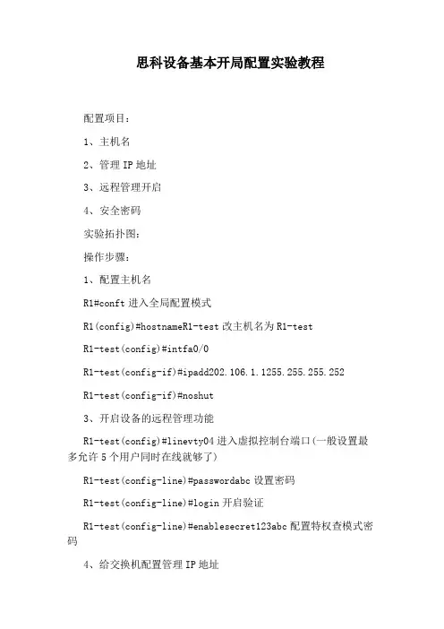
思科设备基本开局配置实验教程配置项目:1、主机名2、管理IP地址3、远程管理开启4、安全密码实验拓扑图:操作步骤:1、配置主机名R1#conft进入全局配置模式R1(config)#hostnameR1-test改主机名为R1-testR1-test(config)#intfa0/0R1-test(config-if)#ipadd202.106.1.1255.255.255.252R1-test(config-if)#noshut3、开启设备的远程管理功能R1-test(config)#linevty04进入虚拟控制台端口(一般设置最多允许5个用户同时在线就够了)R1-test(config-line)#passwordabc设置密码R1-test(config-line)#login开启验证R1-test(config-line)#enablesecret123abc配置特权查模式密码4、给交换机配置管理IP地址SW1(config)#intvlan1交换机配IP是要进vlan1配SW1(config-if)#ipadd202.106.1.2255.255.255.252SW1(config-if)#noshutSW1(config)#noiprouting关闭路由功能SW1(config)#ipdefault-gateway202.106.1.1给交换机指网关,使之连接外网5、开启交换机远程管理SW1(config)#linevty04SW1(config-line)#loginlocal使用本地用户名和密码进行验证,不使用接口密码验证SW1(config-line)#usernametestprivilege15passwordabc加一个用户为test,密码abc,权限设为15级(注:使用这种方法验证不需要设置特权模式密码)6、分别在SW1和R1上做远程管理测试SW1telnetR1:R1telnetsw1:7、配置控制台密码SW1(config)#lineconsole0SW1(config-line)#passwordabcSW1(config-line)#loginSW1(config-line)#enablesecret123abc看了“思科设备基本开局配置实验教程”还想看:。
思科模拟器试验步骤.概要
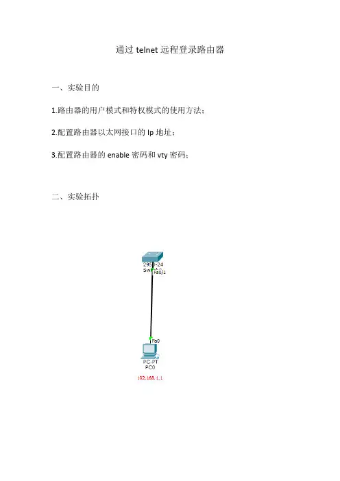
通过telnet远程登录路由器一、实验目的1.路由器的用户模式和特权模式的使用方法;2.配置路由器以太网接口的Ip地址;3.配置路由器的enable密码和vty密码;二、实验拓扑三、实验步骤第一步:按照拓扑图搭建实验环境;第二步:实验步骤;(1)步骤一:配置路由器以太网接口IP地址;1、交换机上基本操作Switch>enable \\进入全局模式Switch#conf t \\进入特权模式Switch(config)#interface vlan 1 \\进入端口Switch(config-if)#ip address 192.168.1.10 255.255.255.0 \\配置IP地址Switch(config-if)#no shutdown \\打开端口Switch(conffig-if)#exit \\回到上一步2、配置虚拟终端密码Switch(config)#line vty 0 4 \\进入vty虚拟终端Switch(config-line)#password 123 \\配置telnet密码Switch(config-line)#login \\注册Switch(config-line)#exit \\回到上一级模式下四、实验调试(1)通过telnet访问路由器在计算机配置网卡的IP地址为192.168.1.1/255.255.255.0,并打开DOS命令行窗口。
首先测试计算机和路由器的IP连通性,在进行Telnet远程登录。
如下:Ping statistics for 192.168.1.10:Packets: Sent = 4, Received = 0, Lost = 4 (100% loss),PC>ping 192.168.1.10Pinging 192.168.1.1 with 32 bytes of data:Request timed out.Reply from 192.168.1.10: bytes=32 time=0ms TTL=255Reply from 192.168.1.10: bytes=32 time=0ms TTL=255Reply from 192.168.1.10: bytes=32 time=0ms TTL=255Ping statistics for 192.168.1.10:Packets: Sent = 4, Received = 3, Lost = 1 (25% loss),Approximate round trip times in milli-seconds:Minimum = 0ms, Maximum = 0ms, Average = 0ms//以上表明计算机能ping通路由器接口fastethernet0/1的IP地址PC>telnet 192.168.1.10 //从计算机telnet路由器以太网卡上的IP地址Trying 192.168.1.10 ...OpenUser Access VerificationPassword:Switch>enablePassword:Switch#//输入vty的密码123、输入enable的密码456,能正常进入路由器的特权模式。
思科基础实验(中英文对照)CCNA,CCNP实验

目录实验一路由器基本配置 (1)实验二静态路由 (3)实验三缺省路由 (5)实验四静态路由&缺省路由&CDP协议 (7)实验五三层交换机实现VLAN间通信 (9)实验六Vtp (11)实验七生成树STP (13)实验八RIP路由协议1 (17)实验九RIP路由协议2 (19)实验十OSPF单区域1 (21)实验十一OSPF单区域2 (22)实验十二OSPF单区域3 (24)实验十三EIGRP (26)实验十四ACL标准访问控制列表 (29)实验十五扩展ACL -1 (31)实验十六扩展ACL -2 (33)实验十七专家级访问控制列表 (36)实验十八动态NAT (37)实验十九NAT地址转换 (39)实验二十单臂路由 (41)实验二十一PPP chap认证 (43)实验二十二研究应用层和传输层协议 (44)实验二十三检查路由 (45)实验二十四研究ICMP 数据包 (47)实验二十五研究第2 层帧头 (49)实验二十六地址解析协议(ARP) (50)实验二十七中间设备用作终端设备 (52)实验二十八管理设备配置 (54)实验一路由器基本配置一、实验设备一台路由器,一台PC,配置线一条。
二、实验要求1.更改路由器名称为RA2.设置password为cisco1,secret为cisco2,vty为cisco3,并要求所有密码都加密。
3.关闭域名查找,命令输入同步。
4.配置以太网口的IP为202.119.249.2195.设置登陆提示信息6.对串行口进行描述(描述信息为:welcome to lixin lab)7.将上述信息保存到tftp server8.将实验过程配置写在记事本中进行粘贴。
9.配置VTY访问权限。
10.禁止路由器进行域名解析。
三、实验步骤Router>enableRouter#configure terminalRouter(config)#hostname RA 设置路由器名RA(config)#enable password cisco1 设置密码RA(config)#enable secret cisco2 设置加密密码RA (config)#no ip domain-lookup关闭域名查找(当我们打错命令时,不会去查找DNS,造成延时)RA (config)#line console 0RA (config-line)#logging synchronous命令输入达到同步(信息提示不会打断你的输入)RA (config-line)#exec-timeout 0 0 设置永久不超时RA (config-line)#exitRA(config)#line vty 0 4RA(config-line)#(enable)password cisco3 设置vty密码RA(config-line)#exitRA(config)#service password-encryption 对密码加密RA(config)#int fastEthernet 0/0RA(config-if)#ip address 202.119.249.1 255.255.255.0 对以太网口fa0/0配置IP RA(config-if)#no shutdown 开启端口RA(config-if)#exitRA(config)#banner motd & welcome welcome to ccna lab & 设置登陆提示信息RA(config)#int fa0/1RA(config-if)#description this is a fast port 描述端口信息RA(config-if)#exitRA(config)#copy running-config tftp 把信息保存到tftp实验二静态路由一、实验设备两台28系列型号路由器通过串口相连。
cisco思科交换机试验手册之-实验03交换机CLI界面调试技巧
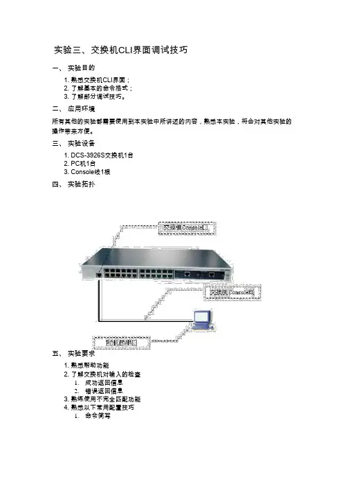
Ethernet0/0/4
Ethernet0/0/5 Ethernet0/0/6 Ethernet0/0/7 Ethernet0/0/8 Ethernet0/0/9
Ethernet0/0/10 Ethernet0/0/11 Ethernet0/0/12 Ethernet0/0/13 Ethernet0/0/14
左光标键?←? 右光标键?→? Ctr+p
Ctr+n Ctr+z Ctr+c Tab 键
光标向左移动一个位置
左右键的配合使用, 可对已输入的命令做覆 盖
光标向右移动一个位置
修改
相当于上光标键?↑?的作用
相当于下光标键?↓?的作用
从其他配置模式(一般用户配置模式除外)直接退回到特权用户模式
打断交换机 ping 其他主机的进程
五、 实验要求 1. 熟悉帮助功能 2. 了解交换机对输入的检查 1. 成功返回信息 2. 错误返回信息 3. 熟练使用不完全匹配功能 4. 熟悉以下常用配置技巧 1. 命令简写
2. 命令完成 3. 命令查询 4. 否定命令的作用 5. 命令历史
aaaaaaaaaaaaaaaaaaa.实验步骤
第一步:?的使用。
parameter!
Ambiguous command
根据已有输入可以产生至少两种不同的解释
Invalid command or parameter
命令解析成功,但没有任何有效的参数记录
Shell Task error ....
多任务时,新的 shell 任务启动失败
命令可解析,但当前模式下不能配置该命令 This command is not exist in current
思科内部资料BGP 基础实验【VIP专享】
BGP目录BGP基础实验 (2)BGP 路由聚合 (62)BGP 默认路由 (84)BGP 路由过滤 (86)BGP条件路由 (95)BGP Peer Group (102)BGP Community (114)BGP Reflector(BGP反射器) (146)BGP Confederation(BGP联邦) (166)BGP 后门路由 (186)BGP Dampening (196)BGP重分布进IGP (209)BGP基础实验说明:上图中所有路由器都配有Loopback地址,地址分别为:R1 Loopback 0 1.1.1.1/32 Loopback 11 11.1.1.1/24R2 Loopback 0 2.2.2.2/32 Loopback 22 22.2.2.2/24R3 Loopback 0 3.3.3.3/32 Loopback 33 33.3.3.3/24R4 Loopback 0 4.4.4.4/32 Loopback 44 44.4.4.4/24所有路由器之间运行OSPF,并将Loopback 0的地址发布到OSPF中,保证全网Loopback 0之间是可以通信的,以此来作为BGP的连接地址。
1.IGP使全网Loopback 0互通说明:使用OSPF保证Loopback 0之间的通信,从而建立BGP连接。
(1)配置各路由器的OSPFR1:r1(config)#router ospf 1r1(config-router)#router-id 1.1.1.1r1(config-router)#network 12.1.1.1 0.0.0.0 area 0r1(config-router)#network 13.1.1.1 0.0.0.0 area 0r1(config-router)#network 1.1.1.1 0.0.0.0 area 0R2:r2(config)#router ospf 1r2(config-router)#router-id 2.2.2.2r2(config-router)#network 12.1.1.2 0.0.0.0 area 0r2(config-router)#network 24.1.1.2 0.0.0.0 area 0r2(config-router)#network 2.2.2.2 0.0.0.0 area 0R3:r3(config)#router ospf 1r3(config-router)#router-id 3.3.3.3r3(config-router)#network 13.1.1.3 0.0.0.0 area 0r3(config-router)#network 34.1.1.3 0.0.0.0 area 0r3(config-router)#network 3.3.3.3 0.0.0.0 area 0R4:r4(config)#router ospf 1r4(config-router)#router-id 4.4.4.4r4(config-router)#network 24.1.1.4 0.0.0.0 area 0r4(config-router)#network 34.1.1.4 0.0.0.0 area 0r4(config-router)#network 4.4.4.4 0.0.0.0 area 0说明:发布各路由器的直连网段与Loopback 0到OSPF中。
思科路由器试验
实验的基本配置一、试验环境IP地址配置:步骤 1. 配置全局配置主机名设置:可以使用哪两个命令离开特权执行模式?exit和end。
可使用什么快捷命令进入特权执行模式?enable。
研究可以通过命令configure 进入的不同配置模式:Router>enableRouter# configure terminal Router(config)#将设备的主机名设为Router1:router(config)# hostname Router1 Router1(config)#步骤 2. 配置MOTD 标语:Router1(config)# banner motd %Enter TEXT message.End with the character ‘%’ *** *** % Router1(config)#1步骤3:配置特权执行口令。
将特权执行口令设置为class:Router1(config)# enable secret classRouter1(config)#步骤4:配置控制台口令:将控制台访问口令设置为cisco:Router1(config)# line console 0Router1(config-line)# password ciscoRouter1(config-line)# login步骤5:配置虚拟线路口令。
将虚拟线路访问口令设置为cisco:Router1(config-line)# line vty 0 4Router1(config-line)# password ciscoRouter1(config-line)# loginRouter1(config-line)# exitRouter1(config)#步骤6:配置路由器的fa0/0 接口:Router1(config)# interface fa0/0Router1(config-if)# description Connection to PC1 with crossover cable Router1(config-if)# ip address 198.168.1.1 255.255.255.0Router1(config-if)# no shutdownRouter1(config-if)# exitRouter1(config)#步骤7:配置路由器的s2/0 接口:Router1(config)# interface s2/0Router1(config-if)# description Connection to Router1 with DCE serial line Router1(config-if)# ip address 198.168.10.1 255.255.255.0Router1(config-if)# no shutdownRouter1(config-if)# exitRouter1(config)#步骤8:配置路由器Router2和Router3:依照以上Router1的配置注:路由器之间连接①串口(须在路由器的DCE端口设置时钟);②以太网设置路由器1(Router1)的s2/0端口(DCE线连接)设置路由器1(Router1)的s2/0端口时钟:Router1(config)# interface s2/0Router1(config-if)# clock rate 12002Router1(config-if)# exit Router1(config)#设置路由器2(Router2)的s3/0端口(DCE线连接)设置路由器2(Router2)的s3/0端口时钟:Router2(config)# interface s3/0Router2(config-if)# clock rate 1200 Router2(config-if)# exit Router2(config)#缺省路由和静态路由试验知识点静态路由静态路由是指由网络管理员手工配置的路由信息。
cisco基础配置实验指导书
[在此处键入]设备基础配置实验1 设备基础配置学习目标•掌握设备系统参数的配置方法,包括设备名称、系统时间及系统时区•掌握Console口空闲超时时长的配置方法•掌握登录信息的配置方法•掌握登录密码的配置方法•掌握保存配置文件的方法•掌握配置路由器接口IP地址的方法•掌握测试两台直连路由器连通性的方法•掌握重启设备的方法拓扑图图1 设备基础配置拓扑图场景您是公司的网络管理员,现在公司购买了两台CISCO 2811系列路由器。
路由器在使用之前,需要先配置路由器的设备名称、系统时间及登录密码等管理信息。
操作步骤步骤一进入特权模式CISCO IOS有三种模式即:用户模式(用“>”表示);特权模式(用“#”表示);配置模式(用“(config) #”表示)。
1.用户模式交换机启动完成后按下Enter键,首先进入的就是用户模式,在些用户模式下用户将受到极大的限制,只能用来查看一些统计信息。
Switch>2.特权模式在用户模式下输入enable(可简写为en)命令就可以进入特权模式,用户在该模式下可以查看并修改Cisco设备的配置。
Switch>enSwitch#3.全局配置模式在特权模式下输入config terminal(可简写conf t)命令即可,用户在该模式下可修改交换机的全局配置。
如修改主机名。
Switch#conf tSwitch(config)#4.各模式退出命令,在任意模式下输入exit,将退出当前模式。
步骤二查看系统信息执行show version命令,查看路由器的软件版本与硬件信息。
Router#show version(截图)命令回显信息中包含了IOS版本,设备型号等信息。
步骤三修改系统时间执行show clock命令查看当前系统时间。
Router#show clock(截图)IOS系统会自动保存时间,但如果时间不正确,可以在特权模式下执行clock set命令修改系统时间。
思科 路由与交换基础实验lab2
实验 1.5.2:路由器基本配置拓扑图地址分配表设备接口IP 地址子网掩码默认网关Fa0/0192.168.1.1 255.255.255.0 不适用R1S0/0/0192.168.2.1 255.255.255.0 不适用Fa0/0192.168.3.1 255.255.255.0 不适用R2S0/0/0192.168.2.2 255.255.255.0 不适用PC1不适用192.168.1.10 255.255.255.0 192.168.1.1 PC2不适用192.168.3.10 255.255.255.0 192.168.3.1学习目标完成本实验后,您将能够:•根据拓扑图进行网络布线。
•清除启动配置并将路由器重新加载为默认状态。
•在路由器上执行基本配置任务。
•配置并激活以太网接口。
•测试并检验配置。
•思考网络实施方案并整理成文档。
场景在本次实验中,您将创建一个与拓扑图类似的网络。
首先请根据拓扑图布线。
然后执行网络连通所需的初始路由器配置。
使用拓扑图中提供的 IP 地址为网络设备分配地址。
网络配置完成后检查路由表,验证网络是否能够正常工作。
本实验是实验1.5.1:网络布线和路由器基本配置的精简版,开始实验之前,您需要熟练掌握基本布线技能和配置文件管理技能。
任务 1:网络布线。
构建一个类似拓扑图所示的网络。
本实验中使用的输出来自 1841 路由器。
您可以在实验中使用任何路由器,只要它具备拓扑图中所要求的接口即可。
请确保使用正确类型的以太网电缆连接主机与交换机、交换机与路由器,以及主机与路由器。
如果您在连接设备时遇到问题,请参考实验 1.5.1:网络布线和基本路由器配置。
请确保将串行 DCE 电缆连接到路由器 R1,并将串行 DTE 电缆连接到路由器 R2。
回答以下问题:应该使用什么类型的电缆将主机 PC 上的以太网接口连接到交换机上的以太网接口?___________应该使用什么类型的电缆将交换机上的以太网接口连接到路由器上的以太网接口?___________应该使用什么类型的电缆将路由器上的以太网接口连接到主机 PC 上的以太网接口?___________任务 2:清除配置并重新启动路由器。