仿德国无刷电调板制作说明
{生产工艺技术}无刷直流电动机调速器组装工艺

{生产工艺技术}无刷直流电动机调速器组装工艺无刷直流电动机调速器组装工艺陈先勇摘要:目前在工业先进的国家里,工业自动化领域中的有刷直流电动机已经逐步被无刷直流电动机所替代。
随着电子技术的进步,电子工业的发展,电子元器件的价格不断下降。
考虑综合指标(系统性能、重量、能量消耗等)之后,无刷直流电机的应用正处上升趋势。
我所设计的是直流无刷电动机的调速器。
关键词:无刷直流电动机;霍尔位置传感器;调速;引言:无刷直流电动机是近年迅速兴起的一种新型电机,它广泛应用与工业,农业,以及军事等领域。
无刷直流电动机系统既保持了直流电动机良好的调速控制特性,由具有寿命长、可靠性高、无换向火花及低噪音等优点,又消除了电刷和换向器的机械接触。
它的应用将越来越广。
1无刷直流电动机的发展和研究状况无刷直流电动机是近年来随着电子技术的迅速发展而发展起来的一种新型直流电动机。
传统的直流电动机存在换向器,因而存在碳刷磨损和碳刷粉末玷污线圈绝缘及其它零部件问题,由此带来火花、维护困难、寿命短等致命缺陷,但直流电动机的调速性能好,起动性能好,故在调速性能要求高的场合,可用直流电动机。
随着电子技术的迅速发展和高能永磁材料的出现,能使直流电动机做得和交流电动机一样结构简单,耐用,而又具有良好的性能。
它是现代工业设备、现代科学技术和军事装备中重要的机电元件之一。
无刷直流电动机是以法拉第的电磁感应定律为基础,而又以新兴的电子技术、数字电子技术和各种物理原理为后盾。
因此它具有很强的生命力。
1.1无刷直流电动机的发展和特点研究和分析微特电机的应用和发展,人们肯定会得出这样的看法和结论:无刷直流电动机将会持续目前迅速发展的势头,并将在要求高性能的应用领域中逐步取代其他类型的电机,占主导地位。
由于无刷直流电动机保持着有刷直流电动机的优良控制特性,在电磁结构上和有刷直流电动机一样,但它的电枢绕组放在定子上,转子上放永久磁钢。
无刷直流电动机的电枢绕组相交流电机的绕组一样,采用多相形式,经由驱动器接到直流电源上,定子采用位置传感器实现电子换向代替有刷电机的电刷和换向器,各相逐次通电产生电流,和转子磁极主磁场相互作用,产生转矩。
自制电调原理说明

无位置传感器直流无刷电机原理位置传感器的直流无刷电机的换向主要靠位置传感器检测转子的位置,确定功率开关器件的导通顺序来实现的,由于安装位置传感器增大了电机的体积,同时安装位置传感器的位置精度要求比较高,带来组装的难度。
研究过程中发现,利用电子线路替代位置传感器检测电机在运行过程中产生的反电动势来确定电机转子的位置,实现换向。
从而出现了无位置传感器的直流无刷电机,其原理框图如图3.1所示。
武汉理工大学硕士学位论文图2-1无位置传感器无刷直流电机原理图无位置传感器无刷直流电机(BLDCM)具有无换向火花、无无线电干扰、寿命长、运行可靠、维护简便等特点,而且不必为一般无刷直流电机所必须的位置传感器带来的对电机体积、成本、制造工艺的较高要求和抗干扰性差问题而担忧,因此应用前景广阔。
由图2-1无刷直流电动机的运行原理图可知,当电机在运行过程中,总有一相绕组没有导通,此时可以在该相绕组的端口检测到该绕组产生反电动势,该反电动势60度的电角度是连续的,由于电机的规格,制造工艺的差别,导致相同电角度的反电动势值是不同,如要通过检测反电动势的数值来确定转子的位置难度极大。
因此必须找到该反电动势与转子位置的关系,才能确定转子的位置。
由于BLDCM的气隙磁场、反电势、以及电流波型是非正弦的,因此采用直交轴坐标变化不是很有效的分析方法。
通常直接利用电机本身的相变量来建立数学模型。
假设三相绕组完全对称,磁路不饱和,不计涡流和磁滞损耗,忽略齿槽相应,则三相绕组的电压平衡方程则可以表示为:根据电压方程得电机的等效电路图,如图2.2所示:2.3.2反电势法电机控制的原理无刷直流电机中,受定子绕组产生的合成磁场的作用,转子沿着一定的方向转动。
电机定子上放有电枢绕组,因此,转子一旦旋转,就会在空间形成导体切割磁力线的情况,根据电磁感应定律可知,导体切割磁力线会在导体中产生感应电热。
所以,在转子旋转的时候就会在定子绕组中产生感应电势,即运动电势,一般称为反电动势或反电势哺1。
无感无刷直流电机之电调设计全攻略

无感无刷直流电机之
电调设计全攻略
ห้องสมุดไป่ตู้
前 言.............................................................................................................................................1
3. 右手螺旋定则(安培定则二)..................................................................................3
1.2 内转子无刷直流电机的工作原理....................................................................................3
1. 左手定则......................................................................................................................2
2. 右手定则(安培定则一)..........................................................................................3
1. BLMC.h中定义的宏................................................................................................56
2. 过零检测与换相代码分析.......................................................................................59
无刷电调编程讲解

无刷电调编程讲解
无刷电调是一种电子元件,常用于控制电机的转速和方向。
为了实现不同的功能,需要对无刷电调进行编程。
下面是无刷电调编程的讲解:
1. 确定编程设备:通常使用电脑和USB转串口线作为编程设备。
2. 安装编程软件:根据无刷电调的品牌和型号,选择相应的编程软件并安装。
3. 连接电调和编程设备:将USB转串口线连接到电脑的USB端口上,另一头连接到电调的编程口上。
4. 进入编程模式:根据电调的说明书,按压指定按键或操作指令,进入编程模式。
5. 编写程序:在编程软件中编写程序,实现电调所需的功能。
常见的功能包括调整最大电流、最大转速和刹车时间等。
6. 下载程序:将编写好的程序下载到电调中,以实现相应的功能。
7. 测试:将电调和电机连接,进行测试以确认编程是否成功。
如果存在问题,可以重新进入编程模式并修改程序。
以上就是无刷电调编程的基本讲解,希望能够帮助大家更好地理解和使用无刷电调。
- 1 -。
航模无刷电调电路图
53 X6 K1X1 1X01
54 X7 K1X1 1X01
55 X8 K1X1 1X01
56 X2 K1X3 1X03
57 X3 K1X3 1X03
58 X1 K1X6 1X06
59 IC1 L4941 BDT D-PAK
60 D3 LGR971 805 SMD-LED 805 grün (Conrad)
20 R21 20k 805
21 R22 20k 805
22 R26 20k 805
23 R27 20k 805
24 R30 20k 805
25 R03 2k2 805
26 R07 2k2 805
27 R09 2k2 805
28 R10 2k2 805
29 R12 2k2 805
30 R13 2k2 805
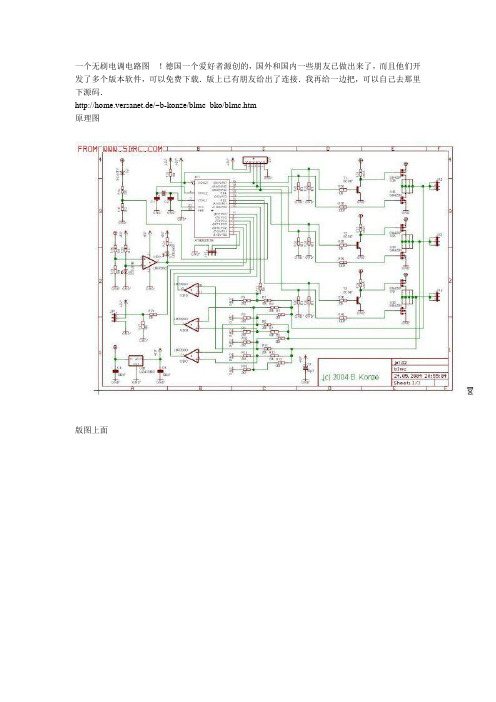
原理图
版图上面
元器件列表
Nr Name Wert Gehäuse Bemerkungen
1 C1 100n 805
2 C3 100n 805
3 R36 100R 805
4 R38 100R 805
5 R40 100R 805
6 R02 10k 805
7 R04 10k 805
8 R06 10k 805
61 D2 LHR974 805 SMD-LED 805 rot (Conrad)
62 IC3 LM339D SO14
63 T4 SI4420N SO8 Oder anderer Logik-Level SO8 N-FET
64 T6 SI4420N SO8
65 T8 SI4420N SO8
66 T5 SI4425P SO8 Oder anderer Logik-Level SO8 P-FET
HOBBYWING无刷电调说明书
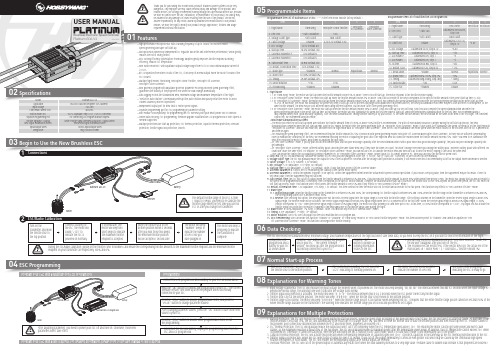
0102Specifications03Begin to Use the New Brushless ESC04ESC Programming05Programmable Items06Data Checking07Normal Start-up ProcessProgrammable Item List of Platinum 60A V4 ESC. (“*” in the form below indicate factory defaults. )Programmable Item List of Multifunction LCD Program BoxUSER MANUALPlatinum 60A V4Brushless Electronic Speed Controller201512031. Flight Mode1.1. In “Fixed-wing” mode, the motor will start up when the throttle amount reaches 5% or above. There is no soft start-up, the motor responds to the throttle increase rapidly.1.2. In “Helicopter (Linear Throttle)” mode, the motor will start up when the throttle amount reaches 5% or above. And it will accelerate to the RPM corresponds to the specific throttle amount in the preset start-up time (4~25s). 1.3. In “Helicopter (Elf Governor)” mode, the motor will start up when the throttle amount reaches 40% or above. And it will complete the speed standardization and enter the speed-governing operation in the preset start-up time(4~25s). In this mode, the motor will standardize its speed every time it starts up. Due to different discharge rates/capabilities of different batteries, the RPM you standardize each time may be a little different. In consequence, at the same throttle amount, the RPM may be a bit different when using different batteries, but this won’t affect the speed-governing effect.1.4. In “Helicopter (Store Governor)” mode, the motor will start up when the throttle amount reaches 40% or above. It will also start up in a very soft way. And it will also complete the speed standardization and enter thespeed-governing operation in the preset start-up time. In this mode, the motor will only standardize its speed the first time when it starts up. When performing RPM standardization for the first time, we recommend using afully-charged battery with good discharge capability. After the RPM standardization, change another battery to fly your aircraft. At the same throttle amount, the RPM should be the same as the RPM of the first flight. For consistent control feel, we recommend using this mode. About RPM Standardization & Others• The motor will enter the soft start-up when user switches the throttle amount from 0 to 40% or above (50% throttle is recommended). The pitch of main blades should be 0 degree during the soft start-up process, the RPMstandardization completes when the soft start-up ends, and the ESC makes the motor enter the speed-governing state. In “Helicopter (Store Governor)” mode, if user wants to re-standardize the speed, he needs to set the flight mode to “Helicopter (Elf Governor)” and save this mode first, and then reset the flight mode back to “Helicopter (Store Governor)”, then the ESC will re-standardize the motor speed when the motor rotates for the first time after the ESC is powered off and then on again.• For ensuring the speed-governing effect, we recommend setting the throttle amount to 85% or below in both speed-governing modes (Helicopter (Elf Governor)&Helicopter (Store Governor), so there will be sufficient compensating room to maintain the consistency of the RPM. We recommend replacing the motor or adjusting the gear ratio if the expected RPM still cannot be reached when the throttle amount exceeds 85%. (Note: You need to re-standardize the RPM after replacing the motor, blades, body frame or adjusting the gear ratio.)• In “Heli Store Governor” mode, if you fly your aircraft with another pack that has poor discharge capability after the RPM standardization (with a pack which has good discharge capability), the pack has poor discharge capability will get damaged.• In “Helicopter (Store Governor)” mode, different battery packs can bring the same stable RPM only if they have the same cell count. This won’t change even when you change the battery pack. However, battery packs with different cell count don’t have the same effect. For instance, in “Helicopter (Store Governor)” mode, you can not use a 4S to calibrate the motor RPM and then use a 6S to drive the motor, hoping it can run at the same RPM. • User can decide the control feel via adjusting Governor Parameter P/I. In “Helicopter (Store Governor)” mode, connect your ESC to a smart phone or PC, then you can check the throttle vs speed chart.2. LiPo Cells: the ESC will automatically calculate the number of LiPo cells you have plugged in as per the “3.7V/Cell” rule if “Auto Calc” is selected. Or user can set this item manually.3. Voltage Cutoff Type: the ESC will gradually reduce the output to 50% of the full power in 3 seconds after the voltage cutoff protection is activated, if soft mode is selected..It will immediately cut off all the output when hard mode is selected.4. Cutoff Voltage: 2.7V-3.7V (custom), 3.3V (default).5. BEC Voltage: 5-8V (adjustable), 0.1V (step), 6V (default).6. Start-up Time: 4-25s (adjustable), 1s (step), 15s (default). (Note: It only functions in Heli Elf/Store Governor Mode)7. Governor Parameter P: Control the ESC maintaining the stability of the current motor speed.8. Governor Parameter I: Control the dynamic response. To be specific, control the supplement extent when the actual motor speed is below expectation. If you choose a very big value, then the supplement may be too much. If select a very small value, then the supplement may not sufficient.9. Auto Restart Time: the ESC will cut off its output when the throttle amount is between 25% and 40%. If you increase the throttle amount to above 40% within preset time period (0-90s), the motor will rapidly start up and accelerate to the speed (in the programmed Restart Acceleration Time) corresponds to the specific throttle amount, complete the shutdown and restart up.If you move the throttle stick to over 40% beyond the preset time period, the ESC will enter the soft start-up process. (Note: This function won’t effect unless the throttle amount is over 25% and it only effects in “Heli Governor Elf/Store” mode.)10. Restart Acceleration Time: 1-3s (adjustable), 0.5s (step), 1.5s (default). This item controls the time the motor will cost to restart and accelerate to the full speed. (This function only effects in “Heli Governor Elf/Store” mode) 11. Brake Type11.1. Proportional Brake: when the throttle range on the transmitter is between 20% and 100%, the corresponding ESC throttle output is between 0% and 100%.When the throttle range on the transmitter is between 20% and 0%, the corresponding brake force is between 0 and 100%.11.2. Reverse: after selecting this option, the RPM signal wire will turn into a reverse signal wire (the signal range is in line with the throttle range). After setting a channel on the transmitter, when the reverse signal length is above 20% signal length, the Reverse mode will be activated. The reverse signal length must be below 20% signal length when the ESC is powered on for the first time. When the reverse signal length is below 20% signal length, 0-100%throttle corresponds to “CW”; when the reverse signal length is above 20% signal length, the motor will stop spinning CW (and then spin CCW); at this time, 0-100% throttle corresponds to “CCW”. Any signal loss will activate the throttle signal loss protection, no matter it happens to the RPM signal wire or the throttle signal cable during the flight.12. Brake Force: 0-100% (adjustable), 1% (step), 0 (default). (Note: this function only effects in “Normal Brake” mode.)13. Timing: 0-30° (adjustable), 1° (step), 15° (default).14. Motor Rotation: CW/CCW. User can adjust this item via a multifunction LCD program box.15. DEO Freewheeling: User can decide this function “Enabled” or “Disabled” in “Fixed Wing” mode or in “Heli (Linear Throttle Response)” mode. This item has been preset to “Enabled” and cannot be adjusted in “Heli (Elf Governor/Store Governor)” mode. This function can brings better throttle linearity.Model Application Input VoltageCont./Peak Current (10s)(Switch-mode) BEC Platinum 60A V4450-480 Class Heli (Propeller: 325-360mm )3-6S LiPo 60A/80A5V-8V Adjustable (Step: 0.1V), 7A/18A Cont./Peak For connecting LCD Program Box/WIFI Express White Throttle Signal Wire/Red & Black BEC Output Wires/Yellow RPM Signal Transmission Wire14AWG Input/Output Wires 49g / 48x30x15.5mmProgrammingConnect the LCD program box and a battery to your ESC as shown above.Platinum 60A V4Program Your ESC with a WIFI Express: For detailed information, please refer to the user manual of WIFI Express.Turn on the transmitter, and then move the throttle stick to the bottom position.After connected to a battery, the ESC will emit “♪123” indicating it’s normally powered on.The motor will emit several beeps to indicate the number of LiPo cells.The motor emits a long beep indicating the ESC is ready to go.08Explanations for Warning Tones1. Input voltage is abnormal: The ESC will measure the input voltage the moment when it’s powered on. The motor will keep beeping “BB, BB, BB” (the interval between two BBs is 1 second) when the input voltage is beyond the normal range. The warning tone won’t stop until the voltage turns normal.2. Throttle signal loss protection is activated: The motor will beep “B-, B-, B-” (the interval between two B-s is 2 seconds) when the ESC doesn’t detect any throttle signal.3. Throttle stick is not at the bottom position: The motor will beep “B-B-B-B-B-” when the throttle stick is not moved to the bottom position.4. Throttle range is too narrow: The motor will beep “B-B-B-B-B-” when the throttle range you set is too narrow (when designing this ESC, it requires that the entire throttle range you set cannot be less than 50% of the whole throttle range available on the transmitter.) The warning tone indicates the throttle range you set is void and you need to set it again.09Explanations for Multiple Protections1. Start-up Protection: The ESC will monitor the motor speed during the start-up process. When the speed stops increasing or the speed increase is not stable, the ESC will take it as a start-up failure. At that time, if the throttle amount is less than 15%, the ESC will automatically try to restart up; if it is larger than 15%, you need to move the throttle stick to back the bottom position and then restart up the ESC. (Possible causes of this problem: poor connection/ disconnection between the ESC and motor wires, propellers are blocked, etc.)2. ESC Thermal Protection: The ESC will gradually reduce the output but won’t cut it off completely when the ESC temperature goes above 110℃. For ensuring the motor can still get some power and won’t causecrashes, so the maximum reduction is about 50% of the full power. The ESC will gradually resume its maximum power after the temperature lowers down. In addition, the ESC temperature cannot exceed 70℃ when it’s powered on. Otherwise, it cannot be started up. (Here we are describing the ESC’s reaction in soft cutoff mode, while if in hard cutoff mode; it will immediately cut off the power.)3. Capacitor Thermal Protection: The ESC will activate this protection when the operating temperature of capacitors goes over 130℃. It protects capacitors in the same way as the ESC thermal protection does to the ESC .4. Throttle Signal Loss Protection: When the ESC detects loss of signal for over 0.25 second, it will cut off the output immediately to avoid an even greater loss which may be caused by the continuous high-speed rotation of propellers or rotor blades. The ESC will resume the corresponding output after normal signals are received.5. Overload Protection: The ESC will cut off the power/output or automatically restart itself when the load suddenly increases to a very high value. (Possible cause to sudden load increase is that propellers are blocked.)0104可编程参数项目及其说明Platinum 60A V420151203空模无刷电子调速器使用说明书下表中带“*”的为出厂默认参数:可编程参数表(英文对照)1、飞行模式1.1 固定翼模式下,油门达到5%启动电机,无缓启动,油门响应迅速;1.2 直升机线性模式下,油门达到5%启动电机,有缓启动,马达在设定的缓启动时间内加速至当前油门应有转速;1.3 直升机精灵定速模式下,油门达到40%启动电机,有缓启动,马达在设定的缓启动时间内完成转速标定进入定速运行状态。
德恩科电机BG系列无刷直流电机产品说明书
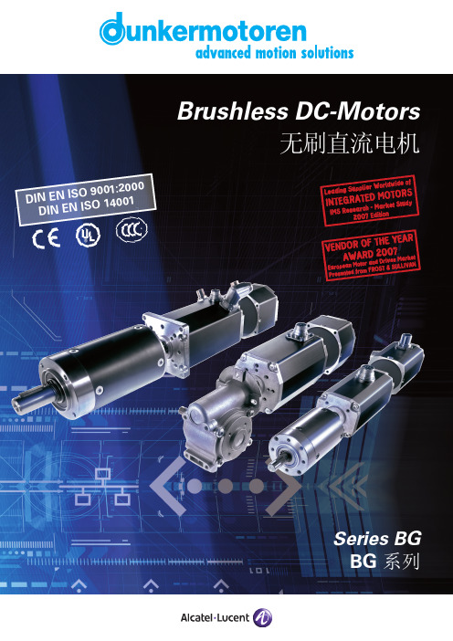
D I NE N I S O9001:2000D I N EN I S O 14001Foreword / 前言To Our Valued Customers,Alcatel-Lucent Dunkermotoren is a world class leader in high quality motion control solutions to meet the ever increasing demands for cost effective and reliable drive solutions.Our comprehensive product range offers the flexibilityto provide customized solutions as well as standardized components.The catalog represents Dunkermotoren´s years of engineering excellence.The Dunkermotoren Team will continue to utilize our outstanding engineering and industrial capabilities to meet the requirements helping you to succeed.Wishing you great success in your business.Nikolaus GräfGeneral Manager 致我们尊敬的客户,阿尔卡特-朗讯旗下的德恩科电机是世界一流的运动控制领域的领先制造商,它提供的优质的传动控制解决方案,满足了客户对成本和可靠性日益增长的的需求。
我们的产品范围包括各种类型的产品,因此具有灵活性;除了提供标准化的部件,还提供用户化的解决方案。
自制无刷电机控制器,牛啊

自制无刷电机控制器,牛啊很早之前就想做一款无刷电机控制器,忙于工作一直没有弄。
最近有点时间画板,打样,焊接,调试,总算顺利的转起来。
期间也遇到很多问题,上网查资料,自己量波形前前后后搞了差不多近一个月,(中间又出差一周)总算搞的差不多了,特意写个总结。
板子外观100*60mm 中等大小。
DC 12V输入,设计最大电流10A.(实际没试过那么大的电机,手头的电机也就5 6A的样子)硬件上可以切换有感(HALL)和无感(EMF)两种模式,外部滑动变阻器调速预留有 PWM输入、刹车、正反转、USB和uart等接口。
先来说下原理无刷电机其实就是直流电机,和传统的DC电机是一样的,只是把有刷的电滑环变成了电子换向器。
因为少了电滑环的摩擦所以寿命静音方面有了很大的提升,转速也更高。
当然难点就在如何获取当前转子的位置好换相,所以又分为两种有感和无感。
有感就是在电机端盖的部位加装霍尔传感器分别相隔30度或60度。
无感就是靠检测悬浮相的感应电动势过零点(后面细讲)。
当然各有各的优缺点,有感在低速方面好,可以频繁启停换相。
无感的结构简单成本低,航模上应用居多。
先说有感,电源首先被分成了3个绕组U V W这个交流电还是有区别的。
它只是3个h桥按一定的顺序导通模拟出来的,本质还是直流电。
电机靠hall位置按一定顺序换相,转速与电压电流有关。
这一点切记,不是换的越快转的越快。
(位置决定换相时刻,电压决定转速)一般调速就是调电压,6步pwm方式是目前常用的。
当然后续还有foc等更好算法。
硬件部分网上基本都是成熟的方案。
三相H桥,H桥一般有上臂mos和下臂mos组成,如果只是简单的做演示上臂选pmos下臂选nmos控制电路简单直接用单片机的io就可以驱动。
但是pmos低内阻的价格高。
功率上面很难做大。
这也就是为什么基本所有的商业控制器全是nmos的原因。
但是上臂用nmos存在一个问题vgs控制电压大与vcc 4v以上才能完全导通。
- 1、下载文档前请自行甄别文档内容的完整性,平台不提供额外的编辑、内容补充、找答案等附加服务。
- 2、"仅部分预览"的文档,不可在线预览部分如存在完整性等问题,可反馈申请退款(可完整预览的文档不适用该条件!)。
- 3、如文档侵犯您的权益,请联系客服反馈,我们会尽快为您处理(人工客服工作时间:9:00-18:30)。
无刷电调板制作说明
参数:
驱动方法: A、ppm 信号驱动
B、I2C 信号驱动
功率: 55W 电压: 7.2-14.8V 电流: 8.0-20A
w w
w .o u r a v r .c o m 转载请注明出处
电路图
w w
w .o u r a v r .c o m 转载请注明出处
元件位置图:
正面:
反面:
w w
w .o u r a v r .c o m 转载请注明出处
元件清单
数量 元件
描述 位号 1 ATMEGA8-16 单片机 IC1
1 78L05 三端稳压块 IC
2
3 IRFR1205 功率MOSFET NA-, NB-, NC- 3 IRFR5305 功率MOSFET NA+, NB+, NC+ 3 BC817 三极管 T1, T2, T3 1 10R 电阻(100) R32 3 100R
电阻(101) R17, R19, R25 3 470R ( 680R ) 电阻(471/681) R2, R5, R8 2 1k 电阻(102) R27, R33
15 4k7
电阻(472) R1,R3, R4, R6,R7, R9,R11,
R12, R13,R15, R18,R20,
R21, R22, R26
5 18k 电阻(183) R10, R14, R16, R23, R24 1 LED 绿LED LED1 1 LED 红LED LED2
17 100nF 电容(104) C1, C2, C3, C4, C5, C6, C7,
C8, C10, C11, C13, C15,
C16, C17, C18,C19, C20
1 1uF
电容(105) C14 1 10uF/50V 电容(106) C12 1 330uF/25V
电解电容 C9
w w
w .o u r a v r .c o m 转载请注明出处
焊接调试方法
第一步:
确认M8最小系统工作正常,步骤如下:
先焊单片机M8及三端稳压块,再焊104、105、106电容共计19个,电阻R10、R26、R32。
如图:
再焊上调试口及接一电源线,测量三端稳压块的电源输入及输出均没有短路,上电并确认78L05输出为5V。
(请使用限流直接电源,如:8V/100mA)
第二步: 烧熔丝位
w w
w .o u r a v r .c o m 转载请注明出处
第三步:
进行BootLoader的烧录 (使用德国人的调试工具SerCon,注意要插上RST跳线帽) 打开MK-Tool,点图中的红圈进入烧录工具
进入如下画面:
w w
w .o u r a v r .c o m 转载请注明出处
点下方 FLASH Bootloader(ISP)…
选中Bootloader文件,烧录完成后显示如下:
w w
w .o u r a v r .c o m 转载请注明出处
第四步:
把没有焊的元件全部补焊全,并请仔细确认没有错焊、漏焊及测量没有短路。
(先不接电机)
w w
w .o u r a v r .c o m 转载请注明出处
第五步:
烧录程序文件(如V0.41版HEX文件)请去掉跳线帽,点Update Software(seriell)…并选中要烧的文件,完成后如下: (请使用限流直接电源,如:8V/100mA)
此时两LED应该都亮,表示电调已经准备好接收油门值。
恭喜你!你可以接上电机进行测试了。
(注:如上面打印出错误信息,并出现红灯闪烁,请查阅德国网站内的相关说明)
w w
w .o u r a v r .c o m 转载请注明出处
第六步
测试,焊上电机,并烧录测试用的HEX文件:(如:Test_Schub_BrushLess-Ctrl_V0_21.hex) (请使用限流直接电源,如:8V/1A)
如使用新西达2212/1000KV的电机,正常电流为0.5-0.8A。
进一步测试请使用PPM或I2C信号。
第七步
请选择合适自己的程序文件并烧录使用。
(可能因各人的电机不一样,暂不提供最终HEX文件)上面使用的到三个HEX文件可以到德国人开源网站上下载。
以上为个人制作心得,提供给大家进行技术交流,如果有涉及版权,请告知。
w w
w .o u r a v r .c o m 转载请注明出处。