A3977步进电机驱动芯片中文说明
A3967SLB中文资料
A3967中文资料A3967SLTB带转换器的微步进驱动芯片特点±750毫安,30 V额定输出Satlington™灌电流驱动器自动电流衰减模式检测/选择3.0 V至5.5 V逻辑电源电压范围混合,快与慢电流衰减模式内部欠压锁定(UVLO)和热关断电路交叉电流保护描述A3967SLB是一个完善的微电机驱动器内置逻辑器。
它的设计操作双极步进电机具有全步进,1/2,1/4,和1/8模式,输出驱动能力30 V和±750毫安。
A3967SLB包括一个固定关断时间的电流调节器,具有慢,快,或混合电流衰减模式的功能。
此电流衰减控制方案可以减少可听到的电流噪音,增加步进精确度,并减少功耗。
A3967SLB的驱动转换非常容易实现,通过简单的“步进”输入中输入一个脉冲电动机将产生一个步骤(全,半,四分,或八分,这取决于两个逻辑输入)。
无需相位顺序表、高频率控制线或复杂的程序。
该A3967SLB是一个理想的适合复杂的微型项目开发的接口驱动芯片。
内部电路保护包括热关机与滞后,电压锁定(UVLO)下和交叉电流保护。
不需要特别的加电排序。
A3967SLB是提供一个24-PIN SOIC封装,能够自由焊接的磨砂100%雾锡引线框架。
选项卡处于接地电位,并且不需要绝缘。
的无铅(100%雾锡引线框架)版本也已经推出。
绝对最大额定值热特性热特性表电气特性在T A = +25°C,V BB = 30 V,V CC = 3.0 V至5.5V(除非另有说明)功能说明设备操作A3967 是一个操作方便、控制线少、完整的微型步进电机驱动器,。
它可用于双极步进电机在全,半,四分和八分模式的操作。
每两个中的电流 H桥输出的调节与固定关断时间脉冲宽度调制(PWM)控制电路。
在每个步骤中的电流由一个外部的值被设置电流检测电阻(R S),一个参考电压(V REF),以及 DAC 的输出电压的输出,通过控制转换。
在上电或复位时,将根据DAC设置和相电流极性初始的内部状态设置转换(见图内部状态情况),并设定的电流调节器两相混合衰减模式。
基于A3977两相步进电机驱动器的应用
的 D S输 出。HO MO ME输 出为 低电 平 时 , 有 的 S E 所 TP 输 入无 效 , 直到雨丽
示 器。
( )HO 3 ME输 出 : 是 分 配器 开 始 状 态 的逻 辑 指 它 ( )S E 4 T P输 入 :T P输 入 的一 个 上 升沿 将 脉 冲 SE 分 配器转 到下 一个 顺序 状态 ,而且使 电机 前进 一个 增 量 , 量 的大小 由输 入 的 MS 增 1和 MS 2的状 态 决定 。
( )D R( 向 ) 入 : 定 电机 的旋 转 方 向。 ( ) 5 I 方 输 决 6
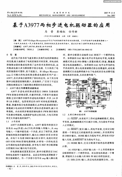
11 工 作 原 理 .
图 1 A3 7 9 7内 部 框 图
12 主 要 引脚 功 能 说 明 .
() 面 1
: 在系 统不 工 作时 选择 睡 眠模 式 , 电 低
平 有效 , 选择 睡 眠模式 可 以减少 功耗 , 当为高 电平 时进
入 正常模 式 。 () 2 雨丽 ( 复位 ) 入 : 电平有效 , 设定 分配 输 低 它
平高 或相 等 , 么 电流衰 减模 式将 会是 慢速 的 , 电流 那 此 衰减模 式 自动选 择将 减少 由于 电动 机 的反 电动 势引起
的电流 波形扭 曲 , 而改善 性能 [ 从 2 1 。
A 9 7 在许 多场 合就得 到 了很好 的应 用 。由于其 自有 37 ,
脉 冲分 配器 使控 制线 最少 , 易操作 , 泛用 于不 适宜 容 广 用 微处理 器 或为 了减 轻微 处理器 的负担 的 系统
个脉 冲, 电机 就 走 一 步 , 需要 相 序 表 、 不 高频 控 制 线 或 复 杂 的 程 序 接 I。 最后 还 介 绍 了A 9 7 典 型 应 用 电路 。 2 ' 37的
电机驱动芯片选型-步进电机和BLDC-Allegro

厂家型号描述Allegro A3901Dual Full Bridge Low Voltage Motor DriverAllegro A3916Dual DMOS Full-Bridge Motor DriverAllegro A3966Dual Full-Bridge PWM Motor DriverAllegro A3967Microstepping Driver with TranslatorAllegro A3977Microstepping DMOS Driver with TranslatorAllegro A3979Microstepping DMOS Driver with TranslatorAllegro A3981K Automotive, Programmable Stepper DriverAllegro A3982DMOS Stepper Motor Driver with TranslatorAllegro A3983DMOS Microstepping Driver with TranslatorAllegro A3984DMOS Microstepping Driver with TranslatorAllegro A3985Digitally Programmable Dual Full-Bridge MOSFET DriverAllegro A3987DMOS Microstepping Driver with TranslatorAllegro A3988Quad DMOS Full Bridge PWM Motor DriverAllegro A3989Bipolar Stepper and High Current DC Motor DriverAllegro A3992DMOS Dual Full-Bridge Microstepping PWM Motor DriverAllegro A3995DMOS Dual Full Bridge PWM Motor DriverAllegro A3998Dual DMOS Full Bridge Motor Driver With Serial Port Control and Allegro A4970Dual Full-Bridge PWM Motor DriverAllegro A4975Full-Bridge PWM Microstepping Motor DriverAllegro A4979Microstepping Programmable Stepper Motor Driver With Stall Dete Allegro A4980K Automotive, Programmable Stepper DriverAllegro A4982DMOS Microstepping Driver with Translator And Overcurrent Prote Allegro A4983DMOS Microstepping Driver with TranslatorAllegro A4984DMOS Microstepping Driver with Translator And Overcurrent Prote Allegro A4985DMOS Microstepping Driver with Translator And Overcurrent Prote Allegro A4986DMOS Dual Full-Bridge PWM Motor Driver With Overcurrent Protect Allegro A4987DMOS Dual Full-Bridge PWM Motor Driver with Overcurrent Protect Allegro A4988DMOS Microstepping Driver with Translator And Overcurrent Prote Allegro A4989Dual Full-Bridge MOSFET Driver with Microstepping Translator Allegro A4990K Automotive Dual Full Bridge DriveAllegro A4992K Automotive Stepper DriverAllegro A4993Automotive Stepper Motor DriverAllegro A5976Microstepping DMOS Driver with TranslatorAllegro A5977Microstepping DMOS Driver with TranslatorAllegro A5979Microstepping DMOS Driver with TranslatorAllegro A5984DMOS Microstepping Driver with Translator And Overcurrent Prote Allegro A5985DMOS Microstepping Driver with Translator And Overcurrent Prote Allegro A5988Bipolar Stepper and High-Current DC Motor DriverAllegro A5989Bipolar Stepper and High-Current DC Motor DriverAllegro A5990Quad DMOS Full-Bridge PWM Motor DriverAllegro AMT49701Quad DMOS Full-Bridge PWM Motor DriverAllegro AMT49702Dual DMOS Full-Bridge Motor Driver后缀“K”表示汽车级产品(通过 AEC-Q100 认证)下列器件已停产:A3986, A3972电桥数量峰值输出电流最大电源电压接口位置反馈最小电源电压Parallel External 2.5 5.50.4Full-Bridge x2 Parallel External 2.7151Full-Bridge x2 PH/EN External 4.75300.75Full-Bridge x2 Translator (Step/DIR)External 4.75300.85Full-Bridge x2 Translator (Step/DIR)External835 2.5Full-Bridge x2 Translator (Step/DIR)External835 2.5Full-Bridge x2 SPI,Translator (Step/DIR)External732 1.4Full-Bridge x2 Translator (Step/DIR)External8352Full-Bridge x2 Translator (Step/DIR)External8352Full-Bridge x2 Translator (Step/DIR)External8352Full-Bridge x2 SPI External1250Full-Bridge x2 Translator (Step/DIR)External850 1.5Full-Bridge x2 Parallel External836 1.2Full-Bridge x4 Parallel,PH/EN External836 1.2Full-Bridge x4 SPI External1550 1.5Full-Bridge x2 PH/EN External836 2.4Full-Bridge x4 SPI External950 1.5Full-Bridge x2 Parallel External7.45451Full-Bridge x2 Parallel External550 1.5Full-Bridge x1 SPI,Translator (Step/DIR)External750 1.5Full-Bridge x2 SPI,Translator (Step/DIR)External 3.332 1.4Full-Bridge x2 Translator (Step/DIR)External8352Full-Bridge x2 Translator (Step/DIR)External835 2.5Full-Bridge x2 Translator (Step/DIR)External8352Full-Bridge x2 Translator (Step/DIR)External8351Full-Bridge x2 Parallel External8352Full-Bridge x2 Parallel External8351Full-Bridge x2 Translator (Step/DIR)External8352Full-Bridge x2 Translator (Step/DIR)External1250 1.2Full-Bridge x2 Parallel External632 1.4Full-Bridge x2 SPI,Translator (Step/DIR)External 3.832 1.4Full-Bridge x2 SPI,Translator (Step/DIR)Open Loop 3.532 1.4Full-Bridge x2 Translator (Step/DIR)External840 2.8Full-Bridge x2 Translator (Step/DIR)External840 2.8Full-Bridge x2 Translator (Step/DIR)External840 2.8Full-Bridge x2 Translator (Step/DIR)External8402Full-Bridge x2 Translator (Step/DIR)External8402Full-Bridge x2 Parallel External840 1.6Full-Bridge x4 Parallel External840 1.6Full-Bridge x4 Parallel External840 1.6Full-Bridge x4 Parallel External4181Full-Bridge x4 Parallel External 3.5151Full-Bridge x2封装DFN Consumer,Industrial QFN Consumer,Industrial SOIC Consumer,Industrial SOIC Consumer,Industrial TSSOP Consumer,Industrial TSSOP Consumer,Industrial TSSOP AutomotiveSOIC Consumer,Industrial TSSOP Consumer,Industrial TSSOP Consumer,Industrial TSSOP Consumer,Industrial TSSOP Consumer,Industrial QFN,LQFP Consumer,Industrial QFN Consumer,Industrial DIP,TSSOP Consumer,Industrial QFN Consumer,Industrial QFN Consumer,Industrial SOIC Consumer,Industrial DIP,SOIC Consumer,Industrial TSSOP Consumer,Industrial TSSOP AutomotiveQFN,TSSOP Consumer,Industrial QFN Consumer,Industrial QFN,TSSOP Consumer,Industrial QFN,TSSOP Consumer,Industrial QFN,TSSOP Consumer,Industrial QFN,TSSOP Consumer,Industrial QFN Consumer,Industrial TSSOP Consumer,Industrial TSSOP AutomotiveTSSOP AutomotiveTSSOP AutomotiveTSSOP Consumer,Industrial TSSOP Consumer,Industrial TSSOP Consumer,Industrial QFN,TSSOP Consumer,Industrial QFN Consumer,Industrial QFN Consumer,Industrial QFN Consumer,Industrial QFN Consumer,Industrial,Of QFN Consumer,Industrial TSSOP AutomotiveFull, Half Step Resolution, Single Supply, Sleep ModeInternal PWM Current Control, Single Supply, OCP Protection, Fault Output, Sleep Mode, Parallel Ope Internal PWM Current Control, Full, Step Resolution, Sleep ModeInternal PWM Current Control, Full, Half, 1/4, 1/8 Step Resolution, Sleep Mode, Automatic Mixed Dec Internal PWM Current Control, Full, Half, 1/4, 1/8 Step Resolution, Sleep Mode, Automatic Mixed Dec Internal PWM Current Control, Full, Half, 1/4, 1/16 Step Resolution, Sleep Mode, Automatic Mixed De Internal PWM Current Control, Full, Half, 1/4, 1/16 Step Resolution, OCP Protection, Programable Fa Internal PWM Current Control, Full, Half Step Resolution, Sleep Mode, Automatic Mixed DecayInternal PWM Current Control, Full, Half, 1/4, 1/8 Step Resolution, Sleep Mode, Automatic Mixed Dec Internal PWM Current Control, Full, Half, 1/4, 1/16 Step Resolution, Sleep Mode, Automatic Mixed De Internal PWM Current Control, Full, Half, 1/4, 1/16 Step Resolution, Sleep Mode, Mixed Decay Internal PWM Current Control, Full, Half, 1/4, 1/16 Step Resolution, OCP Protection, Sleep Mode, Au Internal PWM Current Control, Full, Half, 1/4 Step Resolution, Automatic Mixed DecayInternal PWM Current Control, Full, Half, 1/4 Step Resolution, Automatic Mixed DecayInternal PWM Current Control, Full, Half, 1/4, 1/16 Step Resolution, OCP Protection, Sleep Mode, Mi Internal PWM Current Control, Automatic Mixed DecayInternal PWM Current Control, Full, Half, 1/4, 1/8 Step Resolution, OCP Protection, Sleep Mode, 3.3 Internal PWM Current Control, Full, Half Step Resolution, Sleep ModeInternal PWM Current Control, Full, Half, 1/4, 1/8 Step Resolution, Automatic Mixed DecayInternal PWM Current Control, Full, Half, 1/4, 1/16 Step Resolution, OCP Protection, Programable Fa Internal PWM Current Control, Full, Half, 1/4, 1/16 Step Resolution, OCP Protection, Programable Fa Internal PWM Current Control, Full, Half, 1/4, 1/16 Step Resolution, OCP Protection, Sleep Mode, Au Internal PWM Current Control, Full, Half, 1/4, 1/8, 1/16 Step Resolution, Sleep Mode, Automatic Mix Internal PWM Current Control, Full, Half, 1/4, 1/8 Step Resolution, OCP Protection, Sleep Mode, Aut Internal PWM Current Control, Full, Half, 1/4, 1/8 Step Resolution, OCP Protection, Sleep Mode, Aut Internal PWM Current Control, Full, Half, 1/4 Step Resolution, OCP Protection, Sleep Mode, Mixed De Internal PWM Current Control, Full, Half, 1/4 Step Resolution, OCP Protection, Sleep Mode, Mixed De Internal PWM Current Control, Full, Half, 1/4, 1/8, 1/16 Step Resolution, OCP Protection, Sleep Mod Internal PWM Current Control, Full, Half, 1/4, 1/16 Step Resolution, Sleep Mode, Mixed Decay Internal PWM Current Control, Full Step Resolution, Single Supply, Sleep ModeInternal PWM Current Control, Full, Half, 1/4, 1/16 Step Resolution, Single Supply, OCP Protection, Integrated Current Sense, Internal PWM Current Control, 50V Transient compatible, Full, Half, 1/4, Internal PWM Current Control, Full, Half, 1/4, 1/16 Step Resolution, OCP Protection, Fault Output, Internal PWM Current Control, Full, Half, 1/4, 1/8 Step Resolution, OCP Protection, Sleep Mode, Aut Internal PWM Current Control, Full, Half, 1/4, 1/16 Step Resolution, OCP Protection, Sleep Mode, Au Internal PWM Current Control, Full, Half, 1/4, 1/8, 1/16, 1/32 Step Resolution, Single Supply, OCP Internal PWM Current Control, Full, Half, 1/4, 1/8, 1/16, 1/32 Step Resolution, Single Supply, OCP Internal PWM Current Control, Full, Half, 1/4 Step Resolution, Single Supply, OCP Protection, Sleep Internal PWM Current Control, Full, Half, 1/4 Step Resolution, Single Supply, OCP Protection, Sleep Adaptive Percent fast decay, Adjustable off time, Internal PWM Current Control, Full, Half, 1/4 Ste Internal PWM Current Control, Full, Half, 1/4 Step Resolution, Single Supply, OCP Protection, Sleep Internal PWM Current Control, Half step resolution, Single Supply, OCP Protection, Fault Output, SlParallel OperationAutomatic Mixed DecayAutomatic Mixed Decay, Automatic Mixed Decaytion, Programable Fault Output, Sleep Mode, Advanced DiagnosticsMixed DecayAutomatic Mixed Decay, Automatic Mixed Decay, Mixed Decaytion, Sleep Mode, Automatic Mixed Decaytion, Sleep Mode, Mixed Decayion, Sleep Mode, 3.3/5.0V LDO, Mixed Decayixed Decaytion, Programable Fault Output, Sleep Mode, Advanced Diagnosticstion, Programable Fault Output, Sleep Mode, Advanced Diagnosticstion, Sleep Mode, Automatic Mixed DecayMode, Automatic Mixed Decayion, Sleep Mode, Automatic Mixed Decayion, Sleep Mode, Automatic Mixed DecaySleep Mode, Mixed DecaySleep Mode, Mixed Decayrotection, Sleep Mode, Automatic Mixed Decay, Mixed Decayply, OCP Protection, Programmable Fault Output, Sleep Mode, Mixed Decaye, Full, Half, 1/4, 1/16 Step Resolution, OCP Protection, Programable Fault Output, Sleep Mode, Advanced Dia tion, Fault Output, Sleep Mode, Automatic Mixed Decayion, Sleep Mode, Automatic Mixed Decaytion, Sleep Mode, Automatic Mixed DecaySingle Supply, OCP Protection, Fault Output, Sleep Mode, Adaptive Percent Fast DecaySingle Supply, OCP Protection, Fault Output, Sleep Mode, Adaptive Percent Fast DecayCP Protection, Sleep Mode, Mixed DecayCP Protection, Sleep Mode, Mixed DecayFull, Half, 1/4 Step Resolution, Single Supply, OCP Protection, Sleep Mode, Mixed Decay, diagnostic output CP Protection, Sleep Mode, Mixed Decayon, Fault Output, Sleep Modeep Mode, Advanced Diagnostic d Decay, diagnostic output。
A3967中文资料

A3967SLTB微步进驱动器带转换器负载电源电压,V BB ................ 30 V输出电流,I OUT连续.....................±750毫安的*峰值.................................±850毫安的逻辑电源电压,V CC ........... 7.0 V逻辑输入电压范围,V IN(T W> 30纳秒)............. -0.3 V至+7.0 V(T W <30纳秒)................ -1 V至+7.0 V检测电压,V SENSE ............... 0.68 V参考电压,V REF ................ V CC包装功耗,P D ................................. 见第8页工作温度范围,T A ............................. -20°C至+85°C结温,T J ......... +150°C存储温度范围,T S ......................... -55°C至+150°C*输出电流额定值可能是有限的,占空比,环境温度,和热下沉。
在任何条件下,不超过规定的额定电流或结温度为150℃。
A3967SLB是一个完善的微电机驱动器内置逻辑器。
它的设计操作双极步进电机全,半,季,和第八步模式,输出驱动能力30 V和±750毫安性。
A3967SLB包括一个固定关断时间的电流调节器,有能力在慢,快,或混合电流衰减模式。
此电流衰减控制方案以减少可听到的电流噪音,增加步进精确度,并减少功耗。
A3967SLB通过简单的“步进”输入中输入一个脉冲电动机将产生一个步骤(全,半,四分之一,或八分,这取决于两个逻辑输入)。
有没有相位顺序表、高频率控制线或复杂的界面。
A3977步进集成驱动
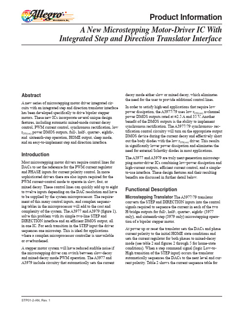
Product Information A New Microstepping Motor-Driver IC With Integrated Step and Direction Translator InterfaceAbstractA new series of microstepping motor driver integrated circuits with an integrated step and direction translator interface has been developed specifically to drive bipolar stepper motors. These new ICs incorporate several unique design features, including automatic mixed-mode current decay control, PWM current control, synchronous rectification, low rDS(on) power DMOS outputs, full-, half-, quarter-, eighth-, and sixteenth-step operation, HOME output, sleep mode, and an easy-to-implement step and direction interface.decay mode either slow or mixed decay, which eliminates the need for the user to provide additional control lines. In order to satisfy high-end applications that require low power dissipation, the A3977/79 uses low rDS(on) n-channel power DMOS outputs rated at ±2.5 A and 35 V. Another benefit of the DMOS outputs is the ability to implement synchronous rectification. The A3977/79 synchronous- rectification control circuitry will turn on the appropriate output DMOS device during the current decay and effectively short out the body diodes with the low rDS(on) driver. This results in significantly lower power dissipation and eliminates the need for external Schottky diodes in most applications. The A3977 and A3979 are truly next-generation microstepping motor-driver ICs combining low-power dissipation and high-current outputs, efficient current control, and a simpleto-use interface. These design features and their resulting benefits are discussed in further detail below.IntroductionMost microstepping motor drivers require control lines for DACs to set the reference for the PWM current regulator and PHASE inputs for current polarity control. In more sophisticated drivers there are also inputs required for the PWM current-control mode to operate in slow, fast, or mixed decay. These control lines can quickly add up to eight to twelve inputs depending on the DAC resolution and have to be supplied by the system microprocessor. The requirement of this many control inputs, and complex sequencing tables in the microprocessor will add to the cost and complexity of the system. The A3977 and A3979 (figure 1), solve this problem with its simple two-line STEP and DIRECTION interface and an efficient DMOS output, all in one IC. For each transition in the STEP input the driver sequences one microstep. This is ideal for applications where a complex microprocessor controller is unavailable or overburdened. A stepper motor system will have reduced audible noise if the microstepping driver can switch between slow-decay and mixed-decay mode PWM operation. The A3977 and A3979 include circuitry that automatically sets the currentFunctional DescriptionMicrostepping Translator The A3977/79 translator converts the STEP and DIRECTION inputs into the control signals required to sequence the current in each of the two H-bridge outputs for full-, half-, quarter-, eighth- (3977 only), and sixteenth-step (3979 only) microstepping operation of a bipolar stepper motor. At power up or reset the translator sets the DACs and phase current polarity to the initial HOME state conditions and sets the current regulator for both phases to mixed-decay mode (see table 2 and figures 2 through 5 for home-state conditions). When a step command signal (logic Low-toHigh transition of the STEP input) occurs the translator automatically sequences the DACs to the next level and current polarity. Table 2 shows the current sequence table forSTP01-2-AN, Rev. 1LOGIC SUPPLY VDD REF. SUPPLY REF DAC + RC1 PWM LATCH BLANKING 4 STEP MIXED DECAY PWM TIMER SENSE1 UVLO AND FAULT 2V REGULATOR BANDGAPVREGCP2CP1 VCP LOAD SUPPLYCHARGE PUMPVBB1 DMOS H BRIDGEVCPOUT 1A OUT1BMS 1 MS 2 HOME SLEEP VPFD SRCONTROL LOGICGATE DRIVERESETTRANSLATORDIRSENSE1DMOS H BRIDGE VBB2OUT 2A OUT2BENABLE PWM TIMER PFD RC 2 4 PWM LATCH BLANKING MIXED DECAY+ DAC-SENSE2Dwg. FP-050-2Figure 1. A3977 Functional Block DiagramTable 1 MS1 MS2L L H H HMicrostepping ResolutionFull Step (2 phase) Half Step Quarter Step Sixteenth Step (3979) Eighth Step (3977)motor operation (DIRECTION input logic Low). For the reverse operation the DIRECTION input is set to logic High and the translator reverses the sequence through table 2. The DAC outputs are used by the PWM current regulator to set the trip point of the current output of each phase. The (micro)step resolution is set by inputs MS1 and MS2 as shown in table 1.L H L H HSTP01-2-AN, Rev. 1Allegro MicroSystems, Inc. 115 Northeast Cutoff Worcester, Massachusetts 01615-0036 U.S.A. 1.508.853.5000; 2Internal PWM Current Control Each H-bridge is controlled by a fixed-off-time PWM current-control circuit that limits the load current to a desired value (ITRIP). Initially, a diagonal pair of source and sink DMOS outputs are enabled and current flows through the motor winding and the current-sense resistor (RS) as shown in figure 6. When the voltage across RS equals the DAC output voltage, the current-sense comparator resets the PWM latch, which turns off either the source drivers (slow-decay mode) or both the source and sink drivers (fast-decay or mixed-decay modes) and the current recirculates as shown in figure 6. During this recirculation the current decreases until the fixed-off time expires. The appropriate output drivers are enabled again, the motor-winding current again increases, and the PWM cycle is repeated. The maximum value of current limiting is set by the selection of RS and the voltage at the VREF input with a transconductance function approximated by: ITRIPmax = VREF / (8RS ) The DAC output reduces the VREF output to the current-sense comparator in precise steps (see table 2 for % ITRIPmax at each step). ITRIP = (% ITRIPmax / 100) × ITRIPmax The internal PWM current-control circuitry uses a one shot to control the time the driver(s) remain(s) off. The one shot off-time, toff , is determined by the selection of an external resistor (RT) and capacitor (CT) connected from the RC timing terminals to ground. The off time is approximated by: toff = RTCT In addition to the fixed-off time of the PWM control circuit, the CT component sets the comparator blanking time. This function blanks the output of the current-sense comparator when the outputs are switched by the internal current-control circuitry. The comparator output is blanked to prevent false over-current detections due to reverse-recovery currents of the clamp diodes, and / or switching transients related to the capacitance of the load. This blanking feature eliminates the low-pass filter between RS and theFigure 6. Current Pathscurrent-sense comparator that is required on most PWM-current regulators. The blank time, tBLANK , can be approximated by: tBLANK = 1900 CT Mixed-Decay Operation Automatic mixed decay is a key feature of the A3977/79. Automatic mixed-decay operation optimizes the current chopping mode in order to achieve the best sinusoidal current waveform for microstepping. Slow decay (figure 7) has the advantage of minimum current ripple. However, when microstepping at higher step rates, slowdecay chopping may fail to properly regulate current on the falling slope of the sine wave when current is decreasing. This is a result of motor BEMF overriding the voltage applied to the motor, forcing the current to increase during the decay period. Figure 8 is a scope plot of motor current that illustrates the limitations of slow-decay chopping. This distortion in the current will cause increased audible noise in the motor.STP01-2-AN, Rev. 1Allegro MicroSystems, Inc. 115 Northeast Cutoff Worcester, Massachusetts 01615-0036 U.S.A. 1.508.853.5000; 3Table 2. Step SequencingHome microstep position at Step Angle 45º; DIR = H; 360° = 4 full steps(A3977 (A3979 only) only) Phase 1 Phase 2 Full 1/2 1/4 1/8 1/16 Current Current Step Step Step Step Step Step [% Itripmax] [% Itripmax] Angle # # # # # (%) (%) (º) 1 1 1 1 100.00 0.00 0.0 2 2 2 3 4 1 2 3 5 6 4 7 8 3 5 9 10 6 11 12 2 4 7 13 14 8 15 16 3 4 5 6 7 8 9 10 11 12 13 14 15 16 17 18 19 20 21 22 23 24 25 26 27 28 29 30 31 32 99.52 98.08 95.69 92.39 88.19 83.15 77.30 70.71 63.44 55.56 47.14 38.27 29.03 19.51 9.80 0.00 –9.80 –19.51 –29.03 –38.27 –47.14 –55.56 –63.44 –70.71 –77.30 –83.15 –88.19 –92.39 –95.69 –98.08 –99.52 9.80 19.51 29.03 38.27 47.14 55.56 63.44 70.71 77.30 83.15 88.19 92.39 95.69 98.08 99.52 100.00 99.52 98.08 95.69 92.39 88.19 83.15 77.30 70.71 63.44 55.56 47.14 38.27 29.03 19.51 9.80 5.6 11.3 16.9 22.5 28.1 33.8 39.4 45.0 50.6 56.3 61.9 67.5 73.1 78.8 84.4 90.0 95.6 101.3 106.9 112.5 118.1 123.8 129.4 135.0 140.6 146.3 151.9 157.5 163.1 168.8 174.4 32 16 31 30 4 8 15 29 28 14 27 26 7 13 25 24 12 23 22 3 6 11 21 20 10 19 18 (A3977 (A3979 only) only) Phase 1 Phase 2 Full 1/2 1/4 1/8 1/16 Current Current Step Step Step Step Step Step [% Itripmax] [% Itripmax] Angle # # # # # (%) (%) (º) 5 9 17 33 –100.00 0.00 180.0 34 35 36 37 38 39 40 41 42 43 44 45 46 47 48 49 50 51 52 53 54 55 56 57 58 59 60 61 62 63 64 –99.52 –98.08 –95.69 –92.39 –88.19 –83.15 –77.30 –70.71 –63.44 –55.56 –47.14 –38.27 –29.03 –19.51 –9.80 0.00 9.80 19.51 29.03 38.27 47.14 55.56 63.44 70.71 77.30 83.15 88.19 92.39 95.69 98.08 99.52 –9.80 –19.51 –29.03 –38.27 –47.14 –55.56 –63.44 –70.71 –77.30 –83.15 –88.19 –92.39 –95.69 –98.08 –99.52 –100.00 –99.52 –98.08 –95.69 –92.39 –88.19 –83.15 –77.30 –70.71 –63.44 –55.56 –47.14 –38.27 –29.03 –19.51 –9.80 185.6 191.3 196.9 202.5 208.1 213.8 219.4 225.0 230.6 236.3 241.9 247.5 253.1 258.8 264.4 270.0 275.6 281.3 286.9 292.5 298.1 303.8 309.4 315.0 320.6 326.3 331.9 337.5 343.1 348.8 354.4STP01-2-AN, Rev. 1Allegro MicroSystems, Inc. 115 Northeast Cutoff Worcester, Massachusetts 01615-0036 U.S.A. 1.508.853.5000; 4STEP INPUTHOME OUTPUTSLOW DECAYMIXED DECAYSLOW DECAYMIXED DECAY100% 70.7% 38.3%PHASE 1 CURRENTFigure 2. A3977 Eighth-Step (Microstepping) Operation–38.3% –70.7% –100%MS1 = MS2 = H, DIR = HMIXED DECAYSLOW DECAYMIXED DECAYSLOW DECAY100% 70.7% 38.3%PHASE 2 CURRENT–38.3% –70.7% –100%Dwg. WK-004-12STEP INPUTNOTE – Refer to table 2 for complete phase current level at each step.HOME OUTPUTSLOW DECAYMIXED DECAYSLOW DECAYMIXED DECAY100% 70.7% 38.3%PHASE 1 CURRENTFigure 3. A3977 Quarter-Step Operation–38.3% –70.7% –100%MS1 = L, MS2 = H, DIR = HMIXED DECAYSLOW DECAYMIXED DECAYSLOW DECAY100% 70.7% 38.3%PHASE 2 CURRENT–38.3% –70.7% –100%Dwg. WK-004-13STP01-2-AN, Rev. 1Allegro MicroSystems, Inc. 115 Northeast Cutoff Worcester, Massachusetts 01615-0036 U.S.A. 1.508.853.5000; 5STEP INPUTHOME OUTPUTMIXED DECAY SLOW DECAY SLOW DECAY SLOW DECAY MIXED DECAY MIXED DECAY SLOW DECAY MIXED DECAY100% 70.7%PHASE 1 CURRENTFigure 4. A3977 Half-Step OperationMS1 = H, MS2 = L, DIR = H–70.7% –100%SLOW DECAY MIXED DECAY SLOW DECAY MIXED DECAY SLOW DECAY MIXED DECAY MIXED DECAY SLOW DECAY100% 70.7%PHASE 2 CURRENT70.7% –100%Dwg. WK-004-14NOTE – Refer to table 2 for complete phase current level at each step.STEP INPUTHOME OUTPUTSLOW DECAY70.7%PHASE 1 CURRENTFigure 5. A3977 Full-Step OperationMS1 = MS2 = L, DIR = H–70.7%SLOW DECAY70.7%PHASE 2 CURRENT–70.7%Dwg. WK-004-15STP01-2-AN, Rev. 1Allegro MicroSystems, Inc. 115 Northeast Cutoff Worcester, Massachusetts 01615-0036 U.S.A. 1.508.853.5000; 6I TRIP SLOW DECAY MIXED DECAY FAST DECAY t FDt OFFDwg. WP-031-4Figure 7. Current-Decay WaveformsFast decay (figure 7) solves the current-regulation problem of slow decay. With almost the full supply across the motor winding it has the ability to quickly get the current out of the winding. The disadvantage of fast decay is the increased current ripple, which in turn causes increased motor heating. Mixed decay (figure 7) splits the fixed-off time of the PWM cycle into fast and then slow decay. When the current reaches ITRIP , the device will go into fast-decay mode until the voltage on the RC terminal decays to the voltage on the PFD terminal (VPFD ). The time that the device operates in fast decay is approximated by: tFD = RTCTln( 0.6VDD / VPFD ) After this fast-decay portion (tFD), the device will switch to slowdecay mode for the remainder of the fixed-off time period. The result is low current ripple, but with increased bandwidth to track the ideal sine wave for microstepping. Although mixed decay improves microstepping performance it will still have higher current ripple than slow decay. The best solution is to use a slow decay on the increasing slope of the sine wave and mixed decay on the falling slope of the sine wave output, which the A3977/97 does automatically. When a step-command signal occurs on the STEP input the translator automatically sequences the DACs to the next level. If the new DAC output level is lower than the previous level then the decay mode for that H-bridge will be set by the voltage level on theFigure 8. Slow-Decay Motor CurrentPFD input (fast, slow, or mixed decay). If the new DAC level is equal or higher to the previous level then the decay mode for that H-bridge will be slow decay (see figures 2 thru 5). Figure 9 is a scope plot of the A3977 motor current with slow decay on the rising slope and mixed decay on the falling slope. For comparison, included is a motor current scope plot (figure 10) of the A3977 set to 100% fast decay on the falling slope of the sine wave and slow decay on the rising slope.Figure 9. Mixed-Decay Motor CurrentSTP01-2-AN, Rev. 1Allegro MicroSystems, Inc. 115 Northeast Cutoff Worcester, Massachusetts 01615-0036 U.S.A. 1.508.853.5000; 7VBBDRIVE CURRENT RECIRCULATION (SLOW-DECAY MODE) RECIRCULATION (FAST-DECAY MODE)Dwg. EP-006-52RSFigure 10. Fast-Decay Motor CurrentFigure 11. Current Paths with Synchronous Rectification EnabledSynchronous Rectification When a PWM off cycle is triggered, by a bridge disable command or internal fixed-off time cycle, load current will recirculate according to the decay mode selected by the control logic (figure 6). The A3977/79 synchronous rectification (SR) feature will turn on the appropriate DMOS devices during the current decay and effectively short out the body diodes with the low rDS(on) driver (figure 11). In fastdecay synchronous rectification mode the voltage across RS is monitored to prevent reverse conduction. Just before the recirculation current reaches zero all of the DMOS devices are turned off and current flows through the body diodes. In a typical stepper-motor application the motor driver IC is in current-decay (recirculation) mode for a higher percentage of the PWM cycle compared to the on time. This means that most of the power dissipation is a result of the forward-voltage drop of the internal body diode of the power DMOS. This is illustrated by the first order power calculation of output power dissipation in slowdecay recirculation mode with and without synchronous rectification enabled for the A3979.Assume: I = ILOAD = 1.5 A, and rDS(on) = on resistance of the sink DMOS transistors = 0.22 ohm, and VF = forward voltage drop of the sink DMOS body diodes = 1.4 V. With synchronous rectification enabled: PD = I2 ( rDS(on) + rDS(on) ) = 1.52 (0.22 + 0.22) = 0.99 W. With synchronous rectification disabled: PD = ( IVF ) + ( I2 (rDS(on) ) = (1.5 × 1.4) + (1.52 × 0.22) = 2.595 W. The power dissipation reduction by using the A3977’s synchronous rectification feature can eliminate the need for external Schottky diodes in most stepper-motor applications thereby saving the cost and board space for these components.STP01-2-AN, Rev. 1Allegro MicroSystems, Inc. 115 Northeast Cutoff Worcester, Massachusetts 01615-0036 U.S.A. 1.508.853.5000; 8Logic Control The A3977/79 SLEEP input is used to minimize power consumption when not in use. This disables much of the internal circuitry including the output DMOS, regulator, and charge pump. Total logic plus motor supply current in sleep mode is <40 μA. Logic Low will put the device into sleep mode; logic High will allow normal operation and starts up the device in the home position. The A3977/79 sleep-mode feature is critical to new designs requiring low off-state current draw. The ENABLE and RESET inputs turn on or off all of the DMOS outputs. Translator inputs are independent of the ENABLE input state so the outputs can be disabled and then stepped to a defined microstep state and then reenabled in this position. The RESET input resets the translator to the home state. The HOME output is a logic output indicator of the initial state of the translator. At power up, the translator is reset to the home state. (See figures 2 through 5 for home state conditions). The HOME output-current level is common to all four microstepping levels in the A3977/79. It can be used as a control input to indicate that the microstepping resolution can be changed at this step without causing a current and therefore torque disturbance to the motor. Protection Circuitry An under-voltage lockout circuit protects the A3977/79 from potential shoot-through currents when the motor supply voltage is applied before the logic supply voltage. All outputs are disabled until the logic supply voltage is above 2.7 V; the control logic is then able to correctly control the state of the outputs. Thermal protection circuitry turns off all the power outputs if the junction temperature exceeds 165°C. As with most integrated thermal shutdown circuits, this is intended only to protect the A3977/79 from failure due to excessive junction temperature and will not necessarily protect the IC from output short circuits. Normal operation is resumed when the junction temperature has decreased by about 15°C.Packaging The A3977/79 is offered in two power packages, a 44-lead plastic power PLCC package (A3977SED) and a 28-lead TSSOP package with exposed thermal pad (A3977SLP and A3979SLP). The 44-lead PLCC has four copper batwing tabs for maximum heat transfer and a thermal resistance of 32°C/W. The 28-lead TSSOP measures only 9.7 mm × 4.4 mm × 0.9 mm and has a thermal resistance of 38°C/W. The TSSOP package is less than 1/4 the size of the PLCC package yet it can achieve close to the same thermal resistance. This is an important advantage in applications that have extreme space constraints.CONCLUSIONAllegro’s new microstepping motor driver ICs, A3977 and A3979, with integrated step and direction translator interface offers several features resulting in application benefits. The A3977/79 features automatic mixed-mode current-decay control, PWM current control, synchronous rectification, low rDS(on) power DMOS outputs, full-, half-, quarter-, eighth-, and sixteenth-step operation, home output, sleep mode, and an easyto-implement step and direction interface. With the A3977 and A3979, Allegro has produced high performance and cost-effective solutions for the next generation of stepper motor drivers.This paper was originally presented at the PCIM 2001 Conference, PowerSystems World, Rosemont, IL on September 10, 2001. Reprinted by permission. Insertion material regarding the A3979 added August 2010.STP01-2-AN, Rev. 1Allegro MicroSystems, Inc. 115 Northeast Cutoff Worcester, Massachusetts 01615-0036 U.S.A. 1.508.853.5000; 9。
L297_L298中文资料
Unit 单位
Vs
Supply voltage 电源电压
10
V
Vi
Input signals 输入信号
7
V
Ptot
Total power dissipation 总功率耗散(Tamb = 70℃)
1
W
Tstg, Tj Storage and junction temperature 储存和结温
-40 to + 150 ℃
Ptot
Total Power Dissipation (Tcase=75℃)总功率耗散(Tcase=75℃)ຫໍສະໝຸດ 25WTop
Junction Operating Temperature 结工作温度
–25 to 130 ℃
Tstg,Tj
Storage and Junction Temperature 储存温度
图 9 L298 引脚图
图 10 L298 内部逻辑图 L298 ABSOLUTE MAXIMUM RATINGS 绝对最大额定值:
Symbol 符 号
Parameter 参数
单 Value 数值 位
VS
Power Supply 电源
50
V
VSS
Logic Supply Voltage 电源电压
7
Sense B
SEN2 分别为两个 H 桥的电流反馈脚,不用时可以直接接地
2;3 4;5
Out 1; Out 2 1Y1、1Y2 输出端
4
6
VS
功率电源电压,此引脚与地必须连接 100nF 电容器
5;7 7;9
Input
1; 1A1、1A2 输入端,TTL 电平兼容
设计报告
简易自动电阻测试仪设计报告摘要:本系统对于不同的量程分别采用恒流源测阻电路、分压法测阻电路和惠更斯桥I/V 变换测阻电路进行电阻测量,充分的发挥出不同电路不同量程的工作特点,并且在软件上进行了校准。
本自动电阻测试仪恒流源以及稳压电路由CA3140、TL431等元器件实现,由ATmega128高速单片机为主控制器,通过其内部自带10位AD 转换器的A/D 转换,对被测电阻两端电压信号进行采样,把连续信号离散化,然后通过LCD 液晶显示屏显示电阻的大小。
该自动测试仪能够较精确的测量1Ω—10M Ω范围内的电阻,其测量误差为±1%,是一个简单易用的电阻测试仪方案。
该系统有,能够自动换档,筛选电阻,并且绘制电阻变化曲线。
实现了测量准确度为±(1%读数+2 字)的三位有效数字显示的简易自动电阻测试仪。
通过偏置电源的改进提高了精度,又通过软件算法的改进再次提高了精度,对22个范围在0~10M 电阻的反复测试,证明了该系统测量精度的明显改善(见表3)。
关键词:A Tmega128 稳压源 恒流源 继电器 电阻分压原理1、系统方案:1、1方案描述 被测电阻 4.7半周克条电阻步进马达模拟放大电路数据采集系统电源图1 系统硬件图简易自动电阻测试仪由5大部分构成:(如图1)1、电源向检测电路提供+-12V ,+5V 模拟电源和+5V 数字电源,模拟地与数字地被光耦隔离。
2、模拟放大电路有三部分构成,第一部分是100Ω档的恒流源测阻电路,第二部分是1K Ω,10K Ω分压法测阻电路,第三部分是1M Ω.档的惠更斯桥I/V 变换测阻电路。
3、步进马达采用信农200步,每步1.8度。
驱动器采用A3977八细分驱动电路。
4、数据采集系统采用ATMEGA128L 单片机。
5、LCD240641、2比较与选择对于电阻的测试方法,一般可以从以下几个方面入手:1、四线测电阻法:为减少接触电阻对测量结果的影响,用一对线通电流(接触电阻对电流的测量无影响),用另一对线测电位(通过的电流很少,接触电阻对电位的影响可忽略)。
A3977
A3977高性能细分驱动器A3977细分驱动器采用高性能专用微步距电脑控制芯片,开放式微电脑可根据用户要求把控制功能设计到驱动器中,组成最小控制系统。
该控制器适合驱动中小型的任何两相或四相混合式步进电机。
由于采用新型的双极性恒流斩波技术,使电机运行精度高, 振动小, 噪声低,运行平稳。
1. 特点:1.1电源电压15~35VDC1.2斩波频率大于35KHZ1.3输入信号与TTL兼容1.4最大驱动电流2.5A/相1.5可驱动两相或四相混合式步进电机1.6双极性恒流斩波方式1.7光电隔离信号输入1.8细分数可选1、2、4、8。
1.9驱动电流可由电位器或开关设定。
1.10外型尺寸:6.6CM*9.4CM*16CM。
1.11重量:______。
2.引脚说明2.1 +35V,GND端为外接直流电源,直流电压范围为+15V~+35V。
2.2 A1,A2端为电机A相。
2.3 B1,B2端为电机B相。
2.4 STEP电机脉冲输入端。
2.5 RW1(SW1)电机电流选择信号端。
2.6 EN驱动器使能信号端。
2.7 DIR电机正反转信号端。
2.8 COM输入信号端地线。
2.9 FAN强制风冷接口3.0 SL休眠控制3.1 +5V外部电源提供(可选)3.电气特性(Tj=25℃)3.1输入电压+15V-+35V,典型值为+24V。
3.2输出相电流0-2.54A可调。
3.3信号逻辑输入最大电流10mA。
3.4下降沿脉冲时间大于5us。
3.5绝缘电阻大于500MΩ;绝缘强度常温1KV,一分钟。
3.6 在电源接通,且不连接插头条件下,电机处于自由状态。
3.7光耦为共阴极。
输入端地线和输出端的地线隔离;使能端为高电平时,电机驱动器使能。
3.8电流选择信号线为高电平时,电机通大电流,为低电平时,电机通小电流,低电流保持锁定状态。
3.9当驱动器长时间以高于2A的电流工作时,建议更换大一点的散热片或安装风扇。
3.10 为可靠起见,电机连线最好使用直径0.75以上的电缆。
全自动贴片机电动飞达电控模块研制
全自动贴片机电动飞达电控模块研制作者:何善印来源:《科技与创新》2017年第11期摘要:简要阐述了电动飞达在贴片机上的应用优势,介绍了电动飞达的机构,重点论述了飞达电控模块方案,对比采用AVR单片机和ARM7控制方案,分析了2种方案的优缺点及其具体应用注意事项,以期为日后的相关工作提供参考。
关键词:电动飞达;AVR单片机;ARM7;电控模块中图分类号:TM910.6 文献标识码:A DOI:10.15913/ki.kjycx.2017.11.112随着电子工业的飞速发展,贴片设备已被广泛应用于大规模电子产品组装生产上,分为自动和手动2种,而全自动贴片机是电子组装行业的发展方向。
供料器FEEDER(飞达)是贴片机的一个重要部件,目前,供料器基本采用的是气动工作方式,就是行业所说的气动飞达。
随着电子产品的发展,要求贴片机向速度更快、精度更高和柔性连接模块化发展。
气动飞达是纯机械结构,各型号间不能替换,速度和精度都不能满足全自动贴片机发展的要求,而电动飞达就是替代气动飞达的产品。
目前,进口高端贴片机使用电动飞达。
1 电动飞达的优点1.1 提高产能电子马达可以微调进给料距离,解决机械飞达使用中不同步贴装的问题,节约了大量的换料和调机时间。
1.2 节约成本使用机械飞达,容易因磁化、气缸不良等原因引发工作误差。
而电动飞达精度高,能够有效解决贴片机贴片零件翻件、侧立、送料不到位、抛料等问题。
1.3 通用性电动飞达用单片机控制,可以通过调整工作参数用于不同型号的贴片机上。
1.4 高安全性机械飞达加装保护装置,结构复杂、难实现,而电动飞达是电气控制的,容易加装保护装置,能够避免因外部问题而造成的设备维修损失。
1.5 人机对话电动飞达可以实时监控每支飞达的贴装数量,可作为设备数据库分析使用。
2 电动飞达的结构2.1 飞达的主要结构飞达包括变速皮带、马达、齿轮、卷取齿轮、加块和控制电路板等部分。
2.2 飞达端口说明飞达采用14Pin易插式插头与机台连接,端口通讯协议如下:引脚1为(24 V)外部供电24 V;引脚2为(NC)空脚;引脚3为(GND)外部供电0 V;引脚4为(NC)空脚;引脚5为(CHECK)飞达状态指示,上电默认低电平,当自动吐料几个后至为高电平;引脚6为(WRITE)写飞达数据控制,高电平有效,与PLUS同时为高电平时,可修改飞达内部数据;引脚7为(PLUS)进给脉冲,高电平有效;引脚8为(RUN)运行指示,飞达运转中输出低电平,待机时高电平;引脚9为(ALM)故障输出,飞达有故障时输出低电平;引脚10为(CONT)飞达插入确认,连接飞达插入保护开关,插入后与GND短接;引脚11为(GND)外部供电0 V;引脚12为(TXD)串口数据发送,TTL电平,逻辑反向;引脚13为(RXD)串口数据接收,TTL电平,逻辑反向;引脚14为(FG)地线,连接外壳。
A3977SED-T中文资料
A3977
Microstepping DMOS Driver with Translator
Features and Benefits
▪ ±2.5 A, 35 V output rating ▪ Low rDS(on) outputs, 0.45 Ω source, 0.36 Ω sink typical ▪ Automatic current decay mode detection/selection ▪ 3.0 to 5.5 V logic supply voltage range ▪ Mixed, fast, and slow current decay modes ▪ Home output ▪ Synchronous rectification for low power dissipation ▪ Internal UVLO and thermal shutdown circuitry ▪ Crossover-current protection
Output current rating may be limited by duty cycle, ambient temperature, and heat sinking. Under any set of conditions, do not exceed the specified current rating or a junction temperature of 150°C. Range K Range S
MIXED DECAY
4
PWM TIMER
DMOS H BRIDGE
PWM TIMER
4
PWM LATCH
BLANKING
MIXED DECAY
- 1、下载文档前请自行甄别文档内容的完整性,平台不提供额外的编辑、内容补充、找答案等附加服务。
- 2、"仅部分预览"的文档,不可在线预览部分如存在完整性等问题,可反馈申请退款(可完整预览的文档不适用该条件!)。
- 3、如文档侵犯您的权益,请联系客服反馈,我们会尽快为您处理(人工客服工作时间:9:00-18:30)。
1 引言随着微步进电机应用的日益广泛,其驱动电路的发展也相当迅速,各类控制芯片的功能越来越丰富,操作也越来越简便。
A3977是一种新近开发出来、专门用于双极型步进电机的微步进电机驱动集成电路,其内部集成了步进和直接译码接口、正反转控制电路、双H桥驱动,电流输出2.5A,最大输出功率可接近90W。
它主要的设计功能包括:自动混合模式电流衰减控制,PWM电流控制,同步整流,低输出阻抗的DMOS电源输出,全、半、1/4及1/8步进操作,HOME输出,休眠模式以及易实现的步进和方向接口等。
其应用电路结构简单、使用及控制方便,有着极其广泛的应用价值。
2 A3977工作特点大多数微步进电机驱动器都需要一些额外的控制线,通过D/A转换器为PWM电流调节器设置参考值以及通过相输入完成电流极性控制等。
许多改进型驱动器仍然需要一些输入来调整PWM电流控制模式使其工作在慢、快或混合衰减模式。
这就需要系统的微处理器额外负担8~12个需依靠D/A变换处理的输入端。
如果一个系统需要如此多的控制输入,而且其微处理器还要存储实现其控制的时序表,这就增加了系统的成本和复杂程度。
A3977可以通过其特有的译码器来使这些功能实现简单化,如图1所示,其最简单的步进输入只需“STEP”(步进)和“DIR”(方向)2条输入线,输出由DMOS的双H桥完成。
通过“STEP”脚简单的输入1个脉冲就可以使电机完成1次步进,省去了相序表,高频控制线及复杂的编程接口。
这使其更适于应用在没有复杂的微处理器或微处理器负担过重的场合。
同时A3977的内部电路可以自动地控制其PWM操作工作在快、慢及混合衰减模式。
这不但降低了电机工作时产生的噪声,也同时省去了一些额外的控制线。
另外,其内部低输出阻抗的N沟道功率DMOS输出结构,可以使其输出达到2.5A,35V。
这一结构的另一优点是,使它能完成同步整流功能。
由于有同步整流流功能,既降低了系统的功耗,又可以在应用时省去外加的肖特基二极管。
A3977的休眠功能可以使系统不工作时的功耗达到最低。
休眠时芯片的大部分内部电路,如输出DMOS、比较器及电荷泵等都将停止工作。
从而在休眠模式时,包括电机驱动电流在内的总电流消耗在40μA以内。
此外,内部保护电路还有利用磁滞实现的热停车、低压关断及换流保护等功能。
集成电路的主要特点:(1)额定输出为:±2.5A,35V。
(2)低输出阻抗,源端0.45Ω,接收端0.36Ω。
(3)自动电流衰减检测并选择混合、快和慢等电流衰减模式。
(4)逻辑电平范围为3.0~5.5V。
(5)HOME输出。
(6)降低功耗的同步整流功能。
(7)内部低压关断、热停车电路及环流保护。
3 A3977引脚说明A3977有两种封装:一种是44引脚铜标塑封(后缀为ED,A3977SED),另一种是28引脚带散热衬垫的塑封(后缀为LP,A3977SLP),其引脚功能说明如表1所示。
电荷泵CP1、CP2可以产生一个高于VBB的门电平,用来驱动DMOS源端的门。
其实现方法是在CP1和CP2之间接一个0.22μF的陶瓷电容。
同时VCP和VBB间也需要一个0.22μF的陶瓷电容作为一个蓄能器,用来操作DMOS的高端设备。
VREG是由系统内部产生,用于对DMOS漏端输出进行操作。
VREG引脚须对地加一个0.22μF的陶瓷电容作为一个蓄能器,用来操作DMOS的高端设备。
VREG是由系统内部产生,用于对DMOS漏端输出进行操作。
VREG引脚须对地加一个0.22μF的电容去耦。
VREG是受内部的电平调节器控制的,发生故障时其输出是被禁止的。
RC1和RC2引脚是为内部PWM电路提供固定截止时间的。
A3977的内部PWM控制电路是用一个脉冲来控制器件的截止时间的。
而这个脉冲的—84—截止时间toff就是由RC1和RC2引脚对地所接的电阻RT和电容CT决定的,即:toff=RT CT式中,电阻RT和电容CT的取值范围分别为12~100kΩ及470~1 500pF〉另外,除了可以为内部PWM控制提供截止时间外,CT还为比较器提供了关断时间tBLANK。
A3977的设计要求当其输出由内部电流控制电路切换时,电路取样比较器的输出是被禁止的。
从而可以防止对过电流检测作出误判断。
tBLANK的取值为:tBLANK=1400CTENABLE输入为低电平有效,它是DMOS输出的使能控制信号。
RESET输入也是低电平有效,当其为低电平时,DMOS的输出将被关断,所有的步进逻辑输入也将被忽略直至其输入变高为止。
4 基本功能说明及应用电路由于采用了内置译码器技术,A3977可以很容易的使用最少的控制线对步进电机实施微步进控制。
具体功能实现如下:(1)步进控制:步进控制信号有步进输入(STEP)、步进模式逻辑输入(MS1,MS2)以及方向控制信号(DIR)。
每一次上电或复位(RESET=0)后,在内置译码器的作用下将H桥的输出预置到HOME输入所对应的输出状态,然后当STEP输入的上升沿到来后,内置译码器将根据步进逻辑的输入值(步进模式见表2)控制H桥的输出,使电机在当前步进模式下产生1次步进。
步进的方向由DIR的输入逻辑控制,其高、低电平分别控制双相电机正反转。
注:①全步进转过的角度为45°。
(2)内部PWM电流控制:每一个H桥都有一个有固定截止时间的PWM电流控制电路,以限制其负载电流在一个设计值。
初始时,对角线上的一对源接收DMOS(一对上下桥臂)处于输出状态,电流流经电机绕组和SENCE脚所接的电流取样电阻(见图1)。
当取样电阻上的压降等于D/A的输出电压时,电流取样比较器将PWM锁存器复位,从而关断源驱动器(上桥臂),进入慢衰减模式;或同时关断源接收驱动器(上下桥臂)进入快或混合衰减模式,使产生环流或电流回流至源端。
该环流或回流将持续衰减至固定截止时间结束为止。
然后,正确的输出桥臂被再次启动,电机绕组电流再次增加,整个PWM循环完成。
其中,最大限流Imax是由取样电阻RS和电流取样比较器的输入电平VREF控制的:Imax=VREF/8RS固定截止时间toff的计算如上所述。
(3)电流衰减模式控制:A3977具有自动检测电流衰减及选择电流衰减模式功能,从而能给微步进提供最佳的正弦电流输出。
电流衰减模式由PFD的输入进行控制,其输入电平的高低控制输出电流处于慢、快及混合衰减模式。
如果PFD的输入电压高于0.6VDD,则选择慢衰减模式。
如果PFD的输入电压低于0.21VDD,则选择快衰减模式。
处于二者之间的PFD电平值将选择混合衰减模式。
其中混合衰减模式将一个PWM周期的固定截止时间分为快、慢两个衰减部分。
当电流达到最大限流Imax 后,系统将进入快衰减模式直至SENCE上的取样电压衰减至PFD的端电压VPFD。
经过tFD的快衰减后,器件将切换至慢衰减模式直至固定截止时间结束。
其中,器件工作在快衰减模式的时间tFD为:tFD=RTCrln(0.6VPFD/VPFD)(4)同步整流控制:同步整流控制是由SR的逻辑输入控制的。
当SR输入为低电平时,同步整流功能将被启动。
此期间,当检测到电流为零值时,可通过关闭同步整流功能来防止负载电流反向,从而防止了电机绕组反方向导通。
而当SR输入为高电平时,同步整流将被禁止。
(5)休眠模式:当SLEEP引脚输入为低电平时,器件将进入休眠模式,从而大大降低器件空闲的功耗。
进入休眠模式后器件的大部分内部电路包括DMOS输出电路、调节器及电荷泵等都将停止工作。
当其输入为高电平时,系统恢复到正常的操作状态并将器件的输出预置到HOME状态。
(6)典型应用电路:其典型应用电路如图1所示,可见其应用电路是非常简单的,其正常工作时仅需5个逻辑输入即可。
5 应用注意事项(1)PFD引入端应加一个0.1μF的电容去耦。
(2)布线时应布一个较厚的地层,最好在本器件周围布上星形地。
(3)最好将芯片直接焊接在线路板上。
(4)为VBB引脚加一个大于47μF的电解电容去耦(越靠近芯片越好)。
(5)为保证输出电流取样的精确,最好使取样电阻有自己单独的地,并将其连到器件周围的星形地上,而且引线越短越好。
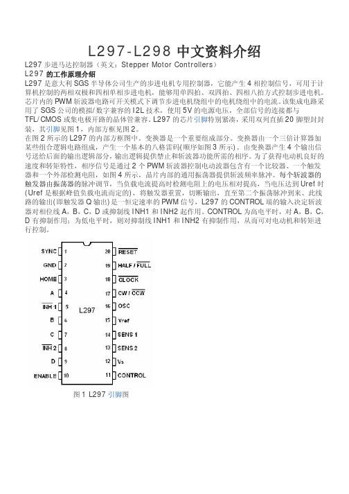
(6)当系统由休眠模式退出后,最少要延迟1ms才可以输入步进命令,从而为驱动DMOS的电荷泵复位提供充裕的时间主要特点及应用:(1)额定输出为:±2.5A,35V.(2)低输出阻抗,源端0.45Ω,接收端0.36Ω.(3)自动电流衰减检测并选择混合、快和慢等电流衰减模式.(4)逻辑电平范围为3.0~5.5V.(5)HOME输出.(6)降低功耗的同步整流功能.(7)内部低压关断、热停车电路及环流保护.A3977带转换器的微步 DMOS 驱动器特点•±2.5 安培 35 伏特输出率•低 r DS(ON)输出(一般为 0.45 欧源极,0.36 欧灌电流)•自驱电流衰减模式检测/选择• 3.0 至 5.5 伏特逻辑电源电压范围•混合、快与慢电流-衰减模式•自动导向输出•对低功率耗散同步整流•内部欠压锁定 (UVLO) 及过热关机电路•交叉电流保护转换器是 A3977 易于实施的关键。
通过简单的在"步进"输入中输入一个脉冲,电动机会产生步进(完整、1/2、1/4 或 1/8 步进,根据两个逻辑输入的情况而定)。
该程序中没有相位顺序表、高频率控制行或复杂的界面。
A3977 界面非常适合复杂的µP 不可用或过载的应用。
内部同步整流控制电路用来改善脉宽调制 (PWM) 操作时的功率消耗。
内部电路保护包括因滞后引起的过热关机、欠压锁定 (UVLO) 及交叉电流保护。
不需要特别的加电排序。
A3977 具有两种功率封装可供选择,即带铜质蝙蝠翼状片的 44 引脚塑料 PLCC 以及带外露隔热盘的(后缀为 LP)的较薄(<1.2 毫米)28 引脚 TSSOP。
该 SLP 封装是无铅产品,且引脚框采用 100% 雾锡电镀。
功能方框图完整型号型号封装类型RoHS符合性温度A3977SED44-铅 PLCC否-20 °C 至 85 °CA3977SED-T44-铅 PLCC是-20 °C 至 85 °CA3977SEDTR44-铅 PLCC否-20 °C 至 85 °CA3977SEDTR-T44-铅 PLCC是-20 °C 至 85 °CA3977SLP28-铅 TSSOP否-20 °C 至 85 °CA3977SLP-T28-铅 TSSOP是-20 °C 至 85 °CA3977SLPTR28-铅 TSSOP否-20 °C 至 85 °CA3977SLPTR-T28-铅 TSSOP是-20 °C 至 85 °CA3977KED-T44-铅 PLCC是-40 °C 至 125 °CA3977KEDTR-T44-铅 PLCC是-40 °C 至 125 °CA3977KLP-T28-铅 TSSOP是-40 °C 至 125 °CA3977KLPTR-T28-铅 TSSOP是-40 °C 至 125 °C特点及注意事项:A3977是一种新近开发出来、专门用于双极型步进电机的微步进电机驱动集成电路,其内部集成了步进和直接译码接口、正反转控制电路、双H桥驱动,电流输出2.5A,最大输出功率可接近90W.它主要的设计功能包括:自动混合模式电流衰减控制,PWM电流控制,同步整流,低输出阻抗的DMOS电源输出,全、半、1/4及1/8步进操作,HOME输出,休眠模式以及易实现的步进和方向接口等.其应用电路结构简单、使用及控制方便,有着极其广泛的应用价值.A3977工作特点大多数微步进电机驱动器都需要一些额外的控制线,通过D/A转换器为PWM电流调节器设置参考值以及通过相输入完成电流极性控制等.许多改进型驱动器仍然需要一些输入来调整PWM电流控制模式使其工作在慢、快或混合衰减模式.这就需要系统的微处理器额外负担8~12个需依靠D/A变换处理的输入端.如果一个系统需要如此多的控制输入,而且其微处理器还要存储实现其控制的时序表,这就增加了系统的成本和复杂程度.A3977可以通过其特有的译码器来使这些功能实现简单化,如图1所示,其最简单的步进输入只需“STEP”(步进)和“DIR”(方向)2条输入线,输出由DMOS的双H桥完成.通过“STEP”脚简单的输入1个脉冲就可以使电机完成1次步进,省去了相序表,高频控制线及复杂的编程接口.这使其更适于应用在没有复杂的微处理器或微处理器负担过重的场合.同时A3977的内部电路可以自动地控制其PWM 操作工作在快、慢及混合衰减模式.这不但降低了电机工作时产生的噪声,也同时省去了一些额外的控制线.另外,其内部低输出阻抗的N沟道功率DMOS输出结构,可以使其输出达到2.5A,35V.这一结构的另一优点是,使它能完成同步整流功能.由于有同步整流流功能,既降低了系统的功耗,又可以在应用时省去外加的肖特基二极管.A3977的休眠功能可以使系统不工作时的功耗达到最低.休眠时芯片的大部分内部电路,如输出DMOS、比较器及电荷泵等都将停止工作.从而在休眠模式时,包括电机驱动电流在内的总电流消耗在40μA以内.此外,内部保护电路还有利用磁滞实现的热停车、低压关断及换流保护等功能.集成电路的主要特点:(1)额定输出为:±2.5A,35V.(2)低输出阻抗,源端0.45Ω,接收端0.36Ω.(3)自动电流衰减检测并选择混合、快和慢等电流衰减模式.(4)逻辑电平范围为3.0~5.5V.(5)HOME输出.(6)降低功耗的同步整流功能.(7)内部低压关断、热停车电路及环流保护.应用注意事项(1)PFD引入端应加一个0.1μF的电容去耦.(2)布线时应布一个较厚的地层,最好在本器件周围布上星形地.(3)最好将芯片直接焊接在线路板上.(4)为VBB引脚加一个大于47μF的电解电容去耦(越靠近芯片越好).(5)为保证输出电流取样的精确,最好使取样电阻有自己单独的地,并将其连到器件周围的星形地上,而且引线越短越好.(6)当系统由休眠模式退出后,最少要延迟1ms才可以输入步进命令,从而为驱动DMOS的电荷泵复位提供充裕的时间.关于步进电机驱动芯片A3977常见问题的解答Q1,问:能否提供A3977的应用笔记?答:是的,请参看应用笔记STP01-2“一种新型的集成步进和方向控制译码器的细分步进电机驱动芯片”。