LEU 安装手册
安装指南 格雷霍尔无线电产品说明书
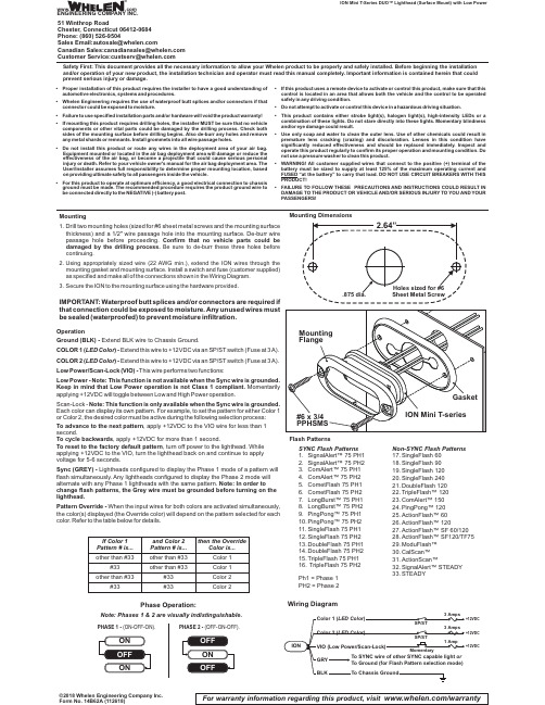
Safety First: This document provides all the necessary information to allow your Whelen product to be properly and safely installed. Before beginning the installation and/or operation of your new product, the installation technician and operator must read this manual completely. Important information is contained herein that could prevent serious injury or damage.•Proper installation of this product requires the installer to have a good understanding of automotive electronics,systems and procedures.•Whelen Engineering requires the use of waterproof butt splices and/or connectors if that connector could be exposed to moisture.•Failure to use specified installation parts and/or hardware will void the product warranty!•If mounting this product requires drilling holes,the installer MUST be sure that no vehicle components or other vital parts could be damaged by the drilling process.Check both sides of the mounting surface before drilling begins.Also de-burr any holes and remove any metal shards or remnants.Install grommets into all wire passage holes.•Do not install this product or route any wires in the deployment area of your air bag.Equipment mounted or located in the air bag deployment area will damage or reduce the effectiveness of the air bag,or become a projectile that could cause serious personal injury or death.Refer to your vehicle owner's manual for the air bag deployment area.The User/Installer assumes full responsibility to determine proper mounting location,based on providing ultimate safety to all passengers inside the vehicle.•For this product to operate at optimum efficiency,a good electrical connection to chassis ground must be made.The recommended procedure requires the product ground wire to be connected directly to the NEGATIVE (-)battery post.•If this product uses a remote device to activate or control this product,make sure that this control is located in an area that allows both the vehicle and the control to be operated safely in any driving condition.•Do not attempt to activate or control this device in a hazardous driving situation.•This product contains either strobe light(s),halogen light(s),high-intensity LEDs or a combination of these lights.Do not stare directly into these lights.Momentary blindness and/or eye damage could result.•Use only soap and water to clean the outer e of other chemicals could result in premature lens cracking (crazing)and discoloration.Lenses in this condition have significantly reduced effectiveness and should be replaced immediately.Inspect and operate this product regularly to confirm its proper operation and mounting condition.Do not use a pressure washer to clean this product.•WARNING!All customer supplied wires that connect to the positive (+)terminal of the battery must be sized to supply at least 125%of the maximum operating current and FUSED “at the battery”to carry that load.DO NOT USE CIRCUIT BREAKERS WITH THIS PRODUCT!•FAILURE TO FOLLOW THESE PRECAUTIONS AND INSTRUCTIONS COULD RESULT IN DAMAGE TO THE PRODUCT OR VEHICLE AND/OR SERIOUS INJURY TO YOU AND YOUR PASSENGERS!ION Mini T-Series DUO™Lighthead (Surface Mount) with Low Power©2018 Whelen Engineering Company Inc.Form No. 14B62A (112618)For warranty information regarding this product, visit /warrantyWiring DiagramNon-SYNC Flash Patterns 17.SingleFlash 6018.SingleFlash 9019.SingleFlash 12020.SingleFlash 24021.DoubleFlash 12022.TripleFlash™Alert™15024.PingPong™12025.ActionFlash™6026.ActionFlash™12027.ActionFlash™SF 60/12028.ActionFlash™SF120/TF7529.ModuFlash™30.CalScan™31.ActionScan™32.SignalAlert™STEADY 33.STEADYSYNC Flash Patterns 1.SignalAlert™75 PH12.SignalAlert™75 Alert™75 Alert™75 etFlash 75 etFlash 75 PH27.LongBurst™75 PH18.LongBurst™75 PH29.PingPong™75 PH110.PingPong™75 PH211.SingleFlash 75 PH112.SingleFlash 75 PH213.DoubleFlash 75 PH114.DoubleFlash 75 PH215.TripleFlash 75 PH116.TripleFlash 75 PH2Ph1 = Phase 1PH2 = Phase 2Mounting DimensionsFlash PatternsMounting1.Drill two mounting holes (sized for #6sheet metal screws and the mounting surface thickness)and a 1/2"wire passage hole into the mounting surface.De-burr wire passage hole before proceeding.Confirm that no vehicle parts could be damaged by the drilling process.Be sure to de-burr these three holes before continuing.ing appropriately sized wire (22AWG min.),extend the ION wires through the mounting gasket and mounting surface.Install a switch and fuse (customer supplied)as specified and make all of the connections shown in the Wiring Diagram.3.Secure the ION to the mounting surface using the hardware provided.IMPORTANT:Waterproof butt splices and/or connectors are required if that connection could be exposed to moisture.Any unused wires must be sealed (waterproofed)to prevent moisture infiltration.Phase Operation:Note: Phases 1 & 2 are visually indistinguishable.PHASE 1 -(ON-OFF-ON).PHASE 2 -(OFF-ON-OFF).OperationGround (BLK) -Extend BLK wire to Chassis Ground.COLOR 1()-LED Color Extend this wire to +12VDC via an SP/ST switch (Fuse at 3A).COLOR 2(LED Color )-Extend this wire to +12VDC via an SP/ST switch (Fuse at 3A).Low Power/Scan-Lock (VIO)-This wire performs two functions:Low Power -Note:This function is not available when the Sync wire is grounded.Keep in mind that Low Power operation is not Class 1compliant.Momentarily applying +12VDC will toggle between Low and High Power operation.Scan-Lock -Note:This function is only available when the Sync wire is grounded.Each color can display its own pattern.For example,to set the pattern for either Color 1or Color 2,the desired color must be active during the following selection process:To advance to the next pattern , apply +12VDC to the VIO wire for less than 1second., apply +12VDC for more than 1 second.To cycle backwards To reset to the factory default pattern , turn off power to the lighthead. While applying +12VDC to the VIO, turn the lighthead back on and continue to apply voltage for 5-6 seconds.Sync (GREY) -Lightheads configured to display the Phase 1 mode of a pattern will flash simultaneously.Any lightheads configured to display the Phase 2 mode will alternate with any Phase 1 lightheads with the same pattern.Note: In order to change flash patterns, the Grey wire must be grounded before turning on the lighthead.Pattern Override -When the input wires for both colors are activated simultaneously,the color(s)displayed (the Override color)will depend on the pattern selected for each color.Refer to the table below for details.If Color 1Pattern # is...#33#33#33and Color 2Pattern # is...other than #33other than #33other than #33other than #33#33then the OverrideColor is...Color 1Color 1Color 2Color 2®ENGINEERING COMPANY INC.51 Winthrop RoadChester, Connecticut 06412-0684Phone: (860) 526-9504SalesEmail:*******************CanadianSales:************************CustomerService:*******************www..comWarnings to InstallersWhelen’s emergency vehicle warning devices must be properly mounted and wired in order to be effective and safe. Read and follow all of Whelen’s written instructions when installing or using this device. Emergency vehicles are often operated under high speed stressful conditions which must be accounted for when installing all emergency warning devices. Controls should be placed within convenient reach of the operator so that he can operate the system without taking his eyes off the roadway. Emergency warning devices can require high electrical voltages and/or currents. Properly protect and use caution around live electrical connections.Grounding or shorting of electrical connections can cause high current arcing, which can cause personal injury and/or vehicle damage, including fire. Many electronic devices used in emergency vehicles can create or be affected by electromagnetic interference.Therefore, after installation of any electronic device it is necessary to test all electronic equipment simultaneously to insure that they operate free of interference from other components within the vehicle. Never power emergency warning equipment from the same circuit or share the same grounding circuit with radio communication equipment.All devices should be mounted in accordance with the manufacturer’s instructions and securely fastened to vehicle elements of sufficient strength to withstand the forces applied to the device. Driver and/or passenger air bags (SRS) will affect the way equipment should be mounted.This device should be mounted by permanent installation and within the zones specified by the vehicle manufacturer, if any.Any device mounted in the deployment area of an air bag will damage or reduce the effectiveness of the air bag and may damage or dislodge the device. Installer must be sure that this device, its mounting hardware and electrical supply wiring does not interfere with the air bag or the SRS wiring or sensors. Mounting the unit inside the vehicle by a method other than permanent installation is not recommended as unit may become dislodged during swerving; sudden braking or collision. Failure to follow instructions can result in personal injury. Whelen assumes no liability for any loss resulting from the use of this warning device. PROPER INSTALLATION COMBINED WITH OPERATOR TRAINING IN THE PROPER USE OF EMERGENCY WARNING DEVICES IS ESSENTIAL TO INSURE THE SAFETY OF EMERGENCY PERSONNEL AND THE PUBLIC.Warnings to UsersWhelen’s emergency vehicle warning devices are intended to alert other operators and pedestrians to the presence and operation of emergency vehicles and personnel. However, the use of this or any other Whelen emergency warning device does not guarantee that you will have the right-of-way or that other drivers and pedestrians will properly heed an emergency warning signal. Never assume you have the right-of-way. It is your responsibility to proceed safely before entering an intersection, driving against traffic, responding at a high rate of speed, or walking on or around traffic lanes. Emergency vehicle warning devices should be tested on a daily basis to ensure that they operate properly. When in actual use, the operator must ensure that both visual and audible warnings are not blocked by vehicle components (i.e.: open trunks or compartment doors), people, vehicles, or other obstructions. It is the user’s responsibility to understand and obey all laws regarding emergency warning devices.The user should be familiar with all applicable laws and regulations prior to the use of any emergency vehicle warning device. Whelen’s audible warning devices are designed to project sound in a forward direction away from the vehicle occupants. However, because sustained periodic exposure to loud sounds can cause hearing loss, all audible warning devices should be installed and operated in accordance with the standards established by the National Fire Protection Association.。
布жде好品 UL控制单元安装器系列说明书

UL Online Certifications DirectoryHome Quick Guide Contact Us UOXX.S5579Control Unit Accessories, SystemPage Bottom Control Unit Accessories, SystemSee General Information for Control Unit Accessories, SystemBOSCH SECURITY SYSTEMS INC S5579 130 Perinton PkwyFairport, NY 14450-9107 USAAudio adjunct systems, Model(s) EVAX 300B, EVAX 300EB, EVAX 400B, EVAX 400EB, EVAX 500B, EVAX 500EB, EVAX 600B, EVAX 600EB, EVAX-100, EVAX-100E, EVAX-150, EVAX-150E, EVAX-200, EVAX-200E, EVAX-25, EVAX-25E, EVAX-50, EVAX-50E, HMB-DP, HMB-MPBattery Supervision Modules, Model(s) D113 (f05)Bell modules, Model(s) D327A, FLM-325-N4City tie kits, Model(s) D184AClass A output modules, Model(s) FLM-325-NA4, FLM-325-NAI4Command centers, Model(s) D1255(f03)(f04)(f06), D1260, D720(f03)(f04)(f06)Contact module, Model(s) FLM-325-I4-A, FLM-325-I4-AIControl Unit accessories, Model(s) D185, D9131AControl Unit Accessory Enclosure, Model(s) AE203R(f07)Conventional Zone Modules, Model(s) FLM-325-CZM4Digital alarm communicator transmitters, Model(s) D9068Direct plug-in transformers, Model(s) D1625(f08), D1640 (f08)Door release/access control modules, Model(s) D9210BC(f02)(f09), D9210BLC(f02)(f09), D9210C (f19)Dual input modules, Model(s) D7041Eight point LED annunciators, Model(s) D730XEight point LED annunciators expanders, Model(s) D7032Enclosures, Model(s) ULPS (+)(f10)Ethernet Module, Model(s) B420 (f19), B426 (f19)Fire annunciator keypads, Model(s) FMR-7036Fireman's Handset, Model(s) MB-FHFireman's phone jacks, Model(s) MB-FJFireman's telephone stations, Model(s) MB-FSInput/output modules, Model(s) B208 (*S)(f18), B308 (*S)(f18), D7043Keypads, Model(s) D1256RB, D1257RB, D1260(f06), D1260B, D1260BLK, D1260R,D1260W, FMR-7033, SC-4000DSCLED modules, Model(s) D9078Main enclosures, Model(s) EVB-CAB2Monitor module, Model(s) FLM-325-IMMonitor modules, Model(s) D326A, D334A, D339A, FLM-325-2I4, FLM-325-I4 Multiplex dual input modules, Model(s) D7052(f01)Multiplex input/output modules, Model(s) D7053(f01)Multiplex mini-single input modules, Model(s) D7044M(f01)Multiplex single input modules, Model(s) D7044(f01)Network adapters, Model(s) D6680-E120 (f12)Notification appliance circuit expander / Power Supply, Model(s) FPP-RNAC-8A-4C +++ (f13)Notification appliance circuit expanders, Model(s) D9072Octal driver modules, Model(s) D7048, D7048BPoint LED annunciators, Model(s) D7030X, D7030X-S2, D7030X-S8Power Supply, Model(s) B520Printers, Model(s) SC9002Relay modules, Model(s) D328A, FLM-325-2R4, FLM-325-2R4-2A, FLM-325-2R4-2AI, FLM-325-2R4-8A, FLM-325-2R4-8AIRemote annunciators, Model(s) FMR-1000-RA# (f14), FMR-1000-RCMD# (f14) Remote keyswitches, Model(s) D7031Remote microphones, Model(s) EVX-RM, EVX-SCReverse polarity modules, Model(s) D185RF communication modules, Model(s) SC-4000, SC-4000 Guard Unit, SC-4000DShort circuit isolators, Model(s) D333A, FLM-325-ISOSingle point multiplex input modules, Model(s) D7044Splitter, Model(s) ICP-SDI-9114(f04) (f15)Surface enclosures, Model(s) EVB-CAB3Telephone storage cabinets, Model(s) MB-TCTransformer enclosures, Model(s) D8004 (f16)Warden's telephone stations, Model(s) MB-WSZone expander subassemblies, Model(s) D8128D (f17), OctoPIT Module# - Complementary Listed for FSYE.(*S) - Compliance to ANSI/SIA CP-01 (2010)(f01) - For use with Model D7024 control units(f02) - For use with Listed Radionics Model D9412/D7412 control units(f03) - May be followed by suffixes R, TD, B or W(f04) - For use with control panels indicated in the installation instructions(f05) - Complementary Listed to AMCX, AOTX, APAW, APOU, NBSX, UTOU(f06) - Complementary Listed to ALVY, AMCX, AMTB, AOTX, AOTX7, APAW, APOU, APOU7, NBSX, NBSX7, UTOU, UTOU7(f07) - Complementary Listed to AMCX(f08) - Complementary Listed to UTOU(f09) - Complementary Listed to ALVY, AMCX, AOTX, AOTX7, APAW, APOU, APOU7, NBSX, NBSX7, UTOU, UTOU7(f10) - Complementary Listed to ALVY, AMCX, AOTX, APAW, APOU, NBSX, UTOU (f12) - Complementary Listed to ALVY, AMCX, AOTX, AOTX7, APAW, APOU, APOU7, NBSX, NBSX7, UTOU, UTOU7(f13) - Complementary Listed to UTRZ(f14) - Complementary Listed to FSYE(f15) - Complementary Listed to ALVY, AMCX, AOTX, AOTX7, APAW, APOU, NBSX, NBSX7, UTOU, UTOU7(f16) - Complementary Listed to AMCX, AOTX, APAW, APOU, NBSX(f17) - Complementary Listed to ALVY, AMCX, AOTX, AOTX7, APAW, APOU, APOU7, NBSX, NBSX7(f18) - Complementary Product Category: AMCX, AMTB, ANET, AOTX, APAW, APOU, NBSX, UOJZ, UTOU(f19) - Complementary Product Category: ALVY, AMCX, AOTX, APAW, APOU, NBSX, UTOU, UTRZ+ - + - Complementary Listed in BP6365 to under ALVY, and in S1871 under AMCX, AOTX, APAW, APOU, NBSX, and UTOU. +++-Complementary Listed to UTRZ under File S5603 Trademark and/or Tradename: ,Last Updated on 2013-10-31 Questions?Print this page Terms of Use Page Top© 2014 UL LLCWhen the UL Leaf Mark is on the product, or when the word "Environment" is included in the UL Mark, please search the UL Environment database for additional information regarding this product's certification.The appearance of a company's name or product in this database does not in itself assure that products so identified have been manufactured under UL's Follow-Up Service. Only those products bearing the UL Mark should be considered to be Certified and covered under UL's Follow-Up Service. Always look for the Mark on the product.UL permits the reproduction of the material contained in the Online Certification Directory subject to the following conditions: 1. The Guide Information, Assemblies, Constructions, Designs, Systems, and/or Certifications (files) must be presented in their entirety and in a non-misleading manner, without any manipulation of the data (or drawings). 2. The statement "Reprinted from the Online Certifications Directory with permission from UL" must appear adjacent to the extracted material. In addition, the reprinted material must include a copyright notice in the following format: "© 2014 UL LLC".。
Relius Documents PC Version 6.1 安装和配置指南说明书

Relius Documents PCVersion 6.1 Installation and ConfigurationAugust 19, 2008Table Of ContentsSection Subject1Overview2Installation and Environment Considerations 3Performing the RDPC Installation4Licensing and Connecting to Your Database 5Database Maintenance6Adding Language and Amendment Packs1OverviewA new, consolidated instruction manual has been compiled for you. This document covers both new installations and upgrades from Relius Documents PC 6.0 or higher. Additionally, the instructions contained in this document are used for standalone and networked workstations.The installations of the RDPC language packs and database server are detailed in separate documentation.The installation of RDPC 6.1 consists of the following basic procedures:1)Read and understand the entire document.2)Back up your system and database.3)Install and configure RDPC 6.1.4)Convert your database.Important NoticeBeginning with Relius Documents PC version 6.0, the application will install to the local hard drive of each workstation. Users who connect to a networked database and centrally located Document Storage Area will still connect to their networked data, but the program files will be installed locally to the workstations.“Network Setup” will no longer exist. Instead, additional workstations will install RDPC using the same installation file as the initial (Admin) workstation. Additionally, program updates must be applied to each workstation.2Installation and Environment ConsiderationsSome Considerations have changed since the last major release of Relius Documents. Please pay special attention to those marked as “NEW” or “Updated.”2.1Hardware Requirements & Supported Operating SystemsAll hardware requirements are specified on our web site(/support/qt_technology.aspx). Once you are logged on to thesupport site, click the “Documents 6.0 Hardware Requirements” link.The only supported operating systems for RDPC workstations are Windows 2000Professional with Service Pack 4 or higher and Windows XP Home or Professional with Service Pack 2 or higher. (Network systems: Windows Server 2003 with Service Pack 1 and Windows 2000 Server with Service Pack 4 are supported for hosting your RDPCnetworked database.) All other operating systems will cause the installation to fail.SunGard Relius cannot guarantee “workaround” scenarios for workstations, regardless of whether they work in the short term.2.2Updated -- Upgrade TimesBecause of the type of update being run on your database for this release, the update ofyour system may take much longer than traditionally expected. The installation process usually takes approximately 1/2 hour or less to complete. However, very large databases may take 1 ½ hours to complete. Due to the nature of this upgrade, the conversionprocess will take significantly more time than in previous upgrades. Some systems may possibly take up to several hours, depending on environment variables, such as database size, the speed and capacity of the database servers and workstations, and the number and size of files in the DP_Data directory. However, once the networked database is updated, the subsequent workstations will take much less time.2.3Internet Licensing SystemSunGard Relius has implemented a more convenient method for licensing your ReliusDocuments system. Now, licensing is available via your Internet connection. When the installation is complete, you will be prompted to license the system. Follow the stepsoutlined in Section 4 of this document. Now, whenever a new or updated module isprovided, you can relicense via the Internet instead of having to call Relius DocumentsSupport.Please note that licensing must be repeated for each standalone system, but only once fora networked database since licensing is now stored in the database.2.4NEW -- Licensing Wide-Area NetworksLicensing your Relius Documents system on a Windows Terminal Server or ICA Citrix Server is now fully supported. Clients who wish to purchase a WAN license mustcontact their Relius Documents Sales representative.2.5NEW -- Program File LocationThe standalone installation of RDPC will default to C:\Program Files\Relius\Docs.Networked systems will have their program files installed to a local drive. These systems must ensure that the location of their DP_Data folder (hereinafter referred to as theDocument Storage Area) is set to a network drive and path consistently mapped acrossthe enterprise so the same drive letter and path will be available to all users. SunGardRelius strongly recommends allowing the defaults to remain in place.2.6Installation MethodsRDPC is only available via download from the SunGard Relius web site. Downloading the file to a local hard drive is recommended and supported. Other methods of installing (network volumes, “push” or “ghost” technology, Z.E.N. Works, Zip Drives, etc.) are not supported or recommended. If a network drive is used to install the software, it must be mapped with a drive letter assigned. Dial-up clients need to contact Relius TechnologySupport before attempting a download.2.7Software fixes and documents via InternetFixes, support files, language updates, and updated documentation are distributed via the web at /support/loginform.aspx. Users must have Internet capability to receive these updates. Once you have logged on, click the “Technology” link tobrowse the list of available material. You can click “Subscribe”(/support/subscribe.aspx) to receive notification of new fixes by e-mail. SunGard no longer sends patches, updates, notifications, and update documentation through the mail, and we strongly urge all users to subscribe to this service.2.8Virtual EnvironmentsThe use of virtual environments and connections, such as Microsoft Virtual Server orVMWare, are not officially supported by SunGard Relius. If a virtual environment isdetected, the installation will abort. For additional technical information regarding thistopic, please contact Relius Technology at 1-800-326-7235.2.9Hidden File ExtensionsSome systems experience certain difficulties when file extensions are hidden within the Windows Operating System. If you encounter this problem, click Tools | Folder Options in Windows Explorer. Select the “View” tab and uncheck “Hide extensions for knownfile types.”2.10Virus ScannersAlthough SunGard Relius does not endorse, support, or recommend any particularmethod, virus protection is encouraged on servers and workstations. The two mostpopular are Symantec’s Norton Anti-Virus and McAfee VirusScan by NetworkAssociates. You should update your virus definition files regularly. Some virus scanners – if active during the installation – can interfere with a successful installation. Symptoms include an error message stating that a file cannot be overwritten. Temporarily disablevirus scanning before starting the installer. Clients using Norton with Script Blockingturned on should test the functionality of RDPC to determine whether script blocking is affecting the application.Please note: NOD32 by ESET has been reported as problematic with RDPC.2.11Security ConsiderationsResponsibility for support of problems and issues related to RDPC running in a locked-down security configuration is that of the end user. Certain circumstances may requirebilling on a time and material basis for troubleshooting. SunGard Relius cannotguarantee that RDPC will install or operate properly on any given locked-down security configuration. RDPC is certified and supported only when run on the default Windows security settings. The local Windows Administrator (or a user with equivalentAdministrator rights) must run the installation.2.12Networked Database Server InformationClients using a networked environment will be required to use one of three varieties ofMicrosoft SQL: SQL Server Express (Default), SQL Server 2000, or SQL Server 2005.SunGard Relius provides clients with SQL Server Express, as well as instructions on the installation and maintenance of SQL Express systems. The other two editions ofMicrosoft SQL are the responsibility of the clients. Contact Relius Technology Support before installing SQL Server 2000 or 2005.2.13Multiple Database Upgrade InformationIf your Relius Documents environment is configured for more than one database/system, the installation is now designed to update all of them during the initial installation. Ifenvironment has multiple databases, the user will see a summary screen that lists each of the databases/systems detected. By default, all databases will be selected for upgrade. For further information, or if you prefer to prevent one or more database from beingupgraded, please call Relius Technology SupportImportant Backup ConsiderationsBecause of the change in database architecture and document storage with RDPC, SunGard Relius strongly urges you to back up your system before beginning this update. In the unlikely event that the update should fail, data recovery may be difficult if you neglected to back up your database and your program files, especially the DP_Data directory. Backups are the sole responsibility of each client; at no point can SunGard Relius accept responsibility for ensuring your data is backed up.It is still important that your Document Storage Area, including the DP_Data, directory be regularly backed up after converting to Relius Documents 6.1. If DP_Data is destroyed, you will have to rebuild you projects to create any needed documents.3Performing the RDPC InstallationPre-Installation Notes:a)Be sure no screen saver will become active during the installation. SunGarddiscourages the use of screen savers whenever running RDPC or its Installer.b)The installation process takes approximately 1 hour or less to complete. Somesystems may possibly take up to several hours, depending on environment variables,such as database size and the number and size of “answer” files in the Data StorageArea, commonly referred to as the location of the DP_Data, Link, and LIBdirectories.c)Review the RDPC system requirements located on our web site(/support/qt_technology.aspx). Do not proceed with the updateif your environment does not meet the minimum system requirements.3.1Remove any icons or shortcuts from the StartUp folder. Services (such as real-timevirus scanning) that may impede or interfere with the installation should be stopped and set to “Manual” before proceeding.Additionally, programs that are set to launch when Windows is started can also bespecified in C:\WINDOWS\WIN.INI. Please edit this file using Notepad. Temporarily remark the entries RUN= and LOAD= by placing a semi-colon (“;”) in front of the line (if programs are specified), then Save and Exit the WIN.INI file. Example of remark: ;RUN=EXAMPLE.EXE3.2Re-start the computer. Windows or other programs may have locked some files that needto be overwritten during the update process.3.3Temporarily disable all virus protection.3.4Download the RDPC 6.1 Installation from the SunGard Relius web site(/Support/Loginform.aspx) and copy it to a temporary location onyour workstation, such as D:\Temp. Do not “run” the install directly from the Internet.Download it first.3.5Click Start | Run, then type in D:\Temp\RDPCv61Setup.exe (where D:\Temp is thelocation of your downloaded file), and click OK.3.6The installation program will copy the necessary temporary files.3.7If installing to a network operating system, such as Windows Server 2003, you willreceive this message. This installation must be run from Windows 2000 Pro or Windows XP only. For information about installing RDPC to a terminal server, please contactRelius Technology Support. Clients already approved for Terminal Services should not see this message.3.8At the “Welcome” screen, click Next.3.9You will be prompted to begin the installation. Click Next.3.10After confirming your features and settings, click Next.3.11Files will begin copying.3.12The first networked system -- and each standalone system -- will receive the followingmessages that the database upgrade scripts are running against the database. This process may take several minutes. Do not interrupt.3.13When the installation is finished, you may be prompted to restart your workstation. Ifprompted, be sure “Yes, I want to restart my computer now” is chosen and clickFinish. Your workstation will shut down all applications and restart. Do not interrupt the process.3.14If action was taken in Step 3.1, restore the icons or shortcuts that were temporarilyremoved from the StartUp group or folder and remove the remark from the RUN= and LOAD= statements from WIN.INI. Restart any services that were temporarily set to“Manual” and – if necessary – place them back in “Automatic” mode.3.15Review the logs that were generated by the installation, specifically,C:\Windows\ReliusLogs\Docs\ReliusInstallDetail.log3.16After finishing all configurations and system settings, proceed to all other workstations,following the appropriate Steps outlined in this Section. Networked databases will only be updated once. All standalone systems will be updated during each workstation’sinstallation.Disclaimers and Copyright NoticesCopyright © 2001-2008 SunGard Relius. All rights reserved.This document and the software it describes may not be reproduced, in whole or in part, in any form whatsoever without the written permission of SunGard Inc. All other products and product names mentioned herein are the copyright of their respective company(ies).This document is provided “as is” without warranty of any kind, either expressed or implied, including, but not limited to, the implied warranties of merchantability, fitness for a particular purpose, or non-infringement.This document could include technical inaccuracies or typographical errors. Changes are periodically added to the information herein. These changes will be incorporated in new editions of the document. SunGard may make improvements and/or changes in the product(s) and/or the Program(s) described in this document at any time.Any third-party programs included herein are subject to a restricted use license and can only be used in conjunction with this application.。
E+H电容液位计安装手册

BA158F/00/zh/05.01
multicap T 电容式物位仪表 DC12TE DC11/16/21TEN DC11/16/21TES
安装操作手册
首页
内容
打印
退出
测量系统
左图: 探头与分离式 Nivotester开关单元配置
,进行限位探测
右图: 探头与分离式Silometer变 送器配置,进行连续物位测量
小 型 壳 体 (F6 F10)的旋向1.-2.-
3.
右下图: 小 型 壳 体 (F6
F10)遮阳罩, 通常 用于室外使用的探头壳 体之上。
壳体旋向
可通过壳体的旋向,合理安排缆塞方向,为 了防止潮湿进入壳体,尤其当室外安装使用 测量探头时,请遵循以下建议:
横向安装的单线塞探头中,线塞应朝下 横向安装的双线塞探头中,两线塞应处于 水平方位 若探头壳体上加装遮阳罩,线塞应处于水 平方位
卫生型螺纹DN 50
可选件 耐蚀钢圈 绝热管
壳体外形尺寸
上排图: 铝质壳体(F6)或塑质壳体(F10, 旧型 号F7)
下排图: 含独立接线室的铝壳(T3):
含 R F I 滤 波 器 ,适 用 于 电 子 插 件 EC17Z, EC61Z, EC11Z
Wheelock Eluxa Multi-Tone (ELMT) 预设 预测安装说明 (墙 天花板挂
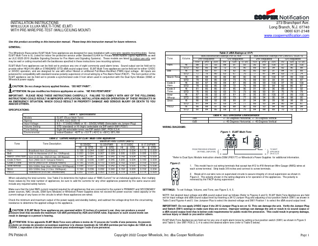
The Wheelock Eluxa series ELMT Multi-Tone appliances are designed for easy installation with a pre-wire capable mounting plate. Series ELMT Multi-Tone is UL Listed for indoor fire protection service under Standard UL464 for Private Mode Audible Signal Appliances as well as ULC-S525-2016 (Audible Signaling Devices for Fire Alarm and Signaling Systems). These models are listed for indoor use only, and may be wall or ceiling mounted with the backboxes specified in these instructions (see mounting options).
Tone
Horn Bell March Time Horn Code 3 Horn Code 3 Tone Slow Whoop Siren HI/LO
Table 2: Current Ratings for ELMT Multi-Tone Appliances
Tone Description
16-33VDC
HI/LO
HI STD
HI STD
HI STD HI STD
HI STD HI STD
HI STD
HI STD
Table 3: dBA Ratings at 10 Ft
应答器及地面电子单元LEU培训资料word资料29页

应答器及地面电子单元(LEU)培训资料2009年2月目录1. CTCS2级系统描述 12. 应答器及LEU 1 2.1. LEU功能及工作原理 12.1.1. 报文接收 12.1.2. 逻辑控制单元 22.1.3. 功率放大 2 2.2. 应答器结构和原理 22.2.1. 应答器结构 22.2.2. 应答器机械特性 32.2.3. 应答器抗杂物理能力 32.2.4. 应答器运用环境 42.2.5. 应答器工作原理 43. 数据 6 3.1. 用户数据 63.1.1. 用户数据表基本要求 63.1.2. 用户数据表格式和填写说明8 3.2. 报文93.2.1. 报文格式93.2.2. 报文编制原则104. 数据写入15 4.1. 应答器数据写入流程154.1.1. 设备数据单说明164.1.2. 数据写入164.1.3. 读取校核16 4.2. LEU数据写入流程174.2.1. 数据写入174.2.2. 读取校核175. LEU亮灯含义18 5.1. CALE板18 5.2. CRTE板185.3. SLEB板196. 试验车检查重点19 6.1. 应答器安装19 6.2. 默认报文类型判断19 6.3. 默认报文故障分析206.3.1. 应答器默认报文206.3.2. LEU默认报文216.3.3. 列控中心默认报文217. 应答器安装及维护21 7.1. 应答器安装轴、角的定义21 7.2. 安装要求23 7.3. 应答器具体的安装步骤如下:247.4. 应答器设备的维护248. 结束语25图索引图 1-1既有线列控系统地面设备连接示意图 1 图 2-1: LEU工作原理框图 1 图 2-2天线与应答器之间的作用原理图 4 图 2-3应答器原理框图 6 图 3-1:临时限速信息变量含义示意图13 图 3-2:临时限速信息管辖范围示意图14 图 3-3:反向运行信息管辖范围示意图14 图 3-4:应答器数据范围示意图15 图 3-5:没有直股发车条件接车进路数据范围示意图15 图 3-6:有直股发车条件接车进路数据范围示意图15图 3-7:由CTCS-2向CTCS-1/0转换时数据范围示意图15 图 3-8:进站口无源应答器反向数据管辖范围15 图 3-9:区间反向无源应答器数据管辖范围15 图 4-1应答器文件结构图16 图 4-2应答器设备数据单16 图 4-3:应答器写入界面16 图 4-4LEU文件结构图17 图 4-5:LEU写入界面17 图 6-1:默认报文标识示意图19 图 7-1:应答器坐标轴定义22 图 7-2:应答器安装旋转角定义22 图 7-3应答器安装空间要求23 图 7-4护轮轨情况下的无金属距离23 图 7-5在轨道中的允许位置范围23表索引表2-1应答器抗杂物A级参数 3 表3-1:用户信息包结构9 表3-2:变量明前缀及含义10 表3-3:用户数据包(ETCS-44)与CTCS数据包的嵌套使用12 表7-1一般情况下应答器安装无金属距离要求23 表7-2应答器安装允许的误差231.CTCS2级系统描述图 1-1既有线列控系统地面设备连接示意图1)既有线CTCS-2级列控系统是基于轨道电路+点式应答器传输列车运行许可信息并采用目标距离模式监控列车安全运行的列车运行控制系统(以下简称列控系统)。
iGyro 3e 简易安装指南说明书

Diese Kurzanleitung zeigt wie man den iGyro 3e in wenigen Minuten ohne PC Program-mierung einbauen kann. Sollten weitere Funktionen notwendig sein, können diese mit-hilfe des USB Interface Adapters oder dem BlueCom Adapter eingestellt werden. Das hierfür verwendete, kostenlose Terminal Programm beinhaltet eine Quick Tip Funktion in der alle Funktionen ausführlich erklärt werden.1. Der iGyro 3e ist wie folgt standardmäßig einzubauen:2. Verbinden Sie die Patchkabel mit dem Empfänger und schließen Sie die Servos an.3. A m Sender wird ein Gainkanal auf einem Drehregler oder Schieber eingestellt der von -100% bis +100% verstellbar ist.4. S chalten Sie Ihren Sender und den Empfänger ein. Drehen Sie den Gain Regler ganz auf 100% und prüfen Sie die Wirkrichtung des Kreisels auf allen Achsen.Der iGyro 3e hat zwei Bereiche die eingestellt werden können:Bereich A, Gainregler 0% bis +100%: Standardmäßig ist hier nur Normalanteil eingestellt. Die LEDs leuchten auf allen Achsen grünBereich B, Gainregler 0% bis -100%: Standardmäßig ist hier auf Querruder und Höhen-ruder zusätzlich zum Normalanteil ein Headinganteil mit eingestellt. Das Seitenruder ist standardmäßig ohne Heading.-100% 0% +100%Berei c h B Berei c h AHinweise: a) Beide Bereiche sind mit der Terminal Software per PC oder Mobiltelefonzusätzlich frei konfigurierbar.b) Sie können, wenn die Kreiselgainwerte erflogen sind, einen 3-Stufenschalter verwen-den, um den iGyro 3e in verschiedene Einstellungen zu schalten. Beispiel:- Schalterstellung 1: Gain ± 0%, Kreisel aus- Schalterstellung 2: Gain +45%, Kreisel Normalmodus - Schalterstellung 3: Gain -40%, Kreisel im HeadingmodusACHTUNG! Zwei wichtige Regeln zur alltäglichen Nutzung des iGyro3e:1. G rundsätzlich zuerst Sender (warten bis vollständig gebootet ist), dann Empfänger einschalten.2. I mmer einen Rudercheck machen. Ab Softwareversion V04 muss der Rudercheck nicht mehr bis an die Endanschläge erfolgen.Hinweis: Die eingelernten Endpunkte können ab V04 auf zwei verschiedene Arten zu-rückgesetzt werden. Dieser Schritt ist notwendig wenn die Ausschläge reduziert werden, oder der iGyro in ein anderes Modell eingebaut werden soll:Möglichkeit a) D rücken Sie die Taste und schalten Sie den iGyro ein. Ein schnelles Blinkensignalisiert die Rücksetzung der Endpunkte. Alle anderen Einstellungen bleiben erhalten.Möglichkeit b) P er USB Interface mit dem PC oder dem BlueCom Adapter und demSmartphone. Die Endpunkte sind damit zurückgesetzt und werden auto-matisch beim Bewegen der Knüppel wieder eingelernt.GARANTIEBESTIMMUNGENWir gewähren deshalb auf das iGyro 3e eine Garantie von 36 Monaten ab dem Ver-kaufsdatum. Die Garantie besteht darin, dass nachgewiesene Materialfehler von uns kostenlos behoben werden. Falsche Anwendung, z.B. durch Verpolung, sehr starke Vibra-tionen, zu hohe Spannung, Nässe, Kraftstoff, Kurzschluss, schließt Garantieansprüche aus. Für Mängel, die auf besonders starke Abnutzung beruhen, gilt dies ebenfalls.HAFTUNGSAUSSCHLUSSSowohl die Einhaltung der Montagehinweise, als auch die Bedingungen beim Betrieb des iGyro 3e sowie die Wartung der gesamten Fernsteuerungsanlage können von uns nicht überwacht werden.Daher übernehmen wir keinerlei Haftung für Verluste, Schäden oder Kosten, die sich aus der Anwendung und aus dem Betrieb der iGyro 3e ergeben oder in irgendeiner Weise damit zusammen hängen können. Soweit es gesetzlich zulässig ist, wird die Pflicht zur Scha-densersatzleistung, gleich aus welchen recht-lichen Gründen, auf den Rechnungsbetrag der Produkte aus unserem Haus, die an dem Ereig-nis beteiligt sind, begrenzt.Wir wünschen viel Erfolg mit Ihrem neuen iGyro 3e !Donauwörth, Februar 2018KurzanleitungPowerBox-Systems GmbH zertifiziert nach DIN EN ISO 9001Ludwig-Auer-Straße 5D-86609 Donauwörth Germany+49-906-99 99 9-200+49-906-99 99 SERVICE HINWEISUm unseren Kunden guten Service bieten zu können, wurde ein Support Forum, für alle Fragen die unsere Produkte betreffen, eingerichtet. Nutzen Sie das Support Forum be-vor Sie uns telefonisch kontaktieren. Sie finden das Forum unter folgender Adresse:5. S timmt die Wirkrichtung nicht, wird diese wie folgt umgepolt:- Taste ca. 5 Sekunden drücken und halten bis alle LED´s erlöschen.- Nach loslassen der Taste leuchtet die grüne LED am Querruder A gedimmt auf. - D rücken Sie die Taste kurz erneut, um die Wirkrichtung für das Querruder A zu verän-dern. Die LED leuchtet dann rot. Ein erneutes kurzes Drücken und die Wirkrichtung istwieder normal. Die Einstellung wird mit jedem Mal umpolen sofort gespeichert. - S oll ein weiterer Kanal umgedreht werden, drücken und halten Sie die Taste. LassenSie die Taste an dem Ausgang los, an dem Sie die Wirkrichtung umdrehen wollen. Drücken Sie die Taste kurz um die Wirkrichtung umzupolen. Die LED ändert die Farbe von Rot auf Grün, mit einem erneuten kurzen Tastendruck wieder zurück. - S oll ein weiterer Kanal umgedreht werden, drücken Sie die Taste einfach wieder er-neut und halten diese. Die LED Sequenz läuft weiter.6. D er iGyro 3e ist jetzt bereit zum Start. Bewegen Sie den Schieberegler in die Mitte um den Kreisel zu deaktivieren.7. B ewegen Sie alle Steuerknüppel einmal mit den eingestellten maximalen Ausschlägen an den Anschlag. Damit werden die Endpunkte eingelernt. Ab der Softwareversion V04 werden diese im iGyro gespeichert.8. S tarten Sie das Modell und fliegen Sie parallel zur Bahn. Jetzt wird die Kreiselempfind-lichkeit erhöht, bis das Modell auf einer Achse zu Schwingen beginnt. Drehen Sie den Regler zurück, bis das Modell in allen Geschwindigkeitsbereichen nicht mehr schwingt. Wird der Einstellvorgang bei Windstille durchgeführt, ist es hilfreich dem Kreisel etwas …Arbeit“ zu geben: L assen Sie die Knüppel …schnalzen“ um zu sehen ob das Modell exakt einrastet und nicht nachschwingt.Flight DirectionFlight Direction E m p f än g e rServos02/2018。
LIMS_EBAIAO版系统安装手册

2
软件安装与注册
1、软件下载
下载地址:/lims_ebaiao
2、软件安装
将安装包解压缩到目标目录后, 双击服务监控如果弹出下图窗口说明此机器没有 安装过本软件。双击 1.安装服务进行软件安装。安装完成后本系统的启动程序 即被加入到 Windows 的服务中, 并设定为自动启动,您可以在本地用浏览器对其 进行访问与操作。
10
************* 联系方式
百奥知信息科技有限公司 1)咨询电话:010-82790315 82790317 2)Email:bioknowsupport@ 3)地址:北京市海淀区大钟寺 13 号院华杰大厦 12B6
Байду номын сангаас
11
7
3、软件登陆
系统默认账号:sa(系统管理员)、stu(学生)、teacher(老师)、pi(老 师)。 在安装电脑上,通过 cmd 命令下“ipconfig”命令或“本地连接”,Internet 协议(TCP/IP)查看安装的 IP 地址,比如 127.0.0.8。 在安装电脑上,打开浏览器(推荐 IE6.0 以上),访问 http://localhost, 可通过上面账号访问系统。 非主机使用,首先得到服务器 IP 地址,可通过开始->程序->修改端口,来 查看服务器 IP 地址和相应端口,在 IE 在地址栏输入 http://主机 IP 地址:端 口 或 http://主机计算机名:端口。 例如主机 IP:192.168.0.12,开启端口 88,则输入: http://192.168.0.12:88 ; Ø 密码修改设定:在进入系统界面的右上方,点击“设定”,进行“密码 设定”。 ==注意==若想使用系统,请保持主机(即安装软件的机器)处于开机 状态。 ==注意== 如果无法出现登录页面,请参见 "\app\dist\help 百奥
- 1、下载文档前请自行甄别文档内容的完整性,平台不提供额外的编辑、内容补充、找答案等附加服务。
- 2、"仅部分预览"的文档,不可在线预览部分如存在完整性等问题,可反馈申请退款(可完整预览的文档不适用该条件!)。
- 3、如文档侵犯您的权益,请联系客服反馈,我们会尽快为您处理(人工客服工作时间:9:00-18:30)。
LEU安装手册北京全路通信信号研究设计院 列控所
目 录
1. LEU的安装位置 (3)
2. LEU安装方式 (3)
3. LEU安装示意图 (3)
4. 2个LEU安装要求的机柜空间 (4)
5. LEU固定底板图 (5)
6. LEU接口配线 (5)
6.1.LEU正面示意图 (5)
6.2.LEU电源卡接口配线表 (6)
6.3.LEU功放卡接口配线表 (6)
6.4.LEU通信卡接口配线表 (7)
7. 冗余LEU配线图 (8)
7.1.正常情况下连接图 (8)
7.2.LEU的切换 (8)
7.3.推荐使用产品 (9)
1.LEU的安装位置
LEU安装在车站列控中心(TCC)机柜中。
2.LEU安装方式
先将LEU的固定底板用四个螺丝固定在19英寸机柜中的托板上,再将LEU推进固定底板,用Φ4mm螺丝将LEU与机柜托板拧紧。
3.LEU安装示意图
LEU
4. 2个LEU 安装要求的机柜空间
2个LEU 安装要求的机柜空间为:高:200mm 、宽:444mm 、深:500mm
机柜后面Back of the
5.LEU固定底板图
6. LEU接口配线
6.1.L EU正面示意图
A为电源卡,B为CPU卡,C为通信卡,D为功放卡。
各板卡接插件采用HARTING 48针接插件,型号:09 06 248 3201。
外壳附件编号:0906*******、0906*******。
外壳编号件:0906*******、0906*******。
6.2.L EU电源卡接口配线表
Pin №z row d row
32 NC NC
30 NC NC
28 NC NC
26 NC NC
24 NC NC
22 NC NC
20 NC NC
18 NC NC
16 NC NC
14 NC NC
12 NC NC
10 NC NC
8 NC DC24V-
6 NC NC
4 NC DC24V+
2 NC NC
6.3.L EU功放卡接口配线表
Pin №z row d row
32 NC NC
30 NC NC
28 NC NC
26 BALISE1P BALISE1N
24 NC NC
22 NC NC
20 NC NC
18 BALISE2P BALISE2N
16 NC NC
14 NC NC
12 NC NC
10 BALISE3P BALISE3N
8 NC NC
6 NC NC
4 NC NC
2 BALISE4P BALISE4N
说明: BALISE1P和BALISE1N为应答器1输出,BALISE2P和BALISE2N为
应答器2输出,BALISE3P和BALISE3N为应答器3输出,BALISE4P和BALISE4N为应答器4输出。
每一对应答器输出采用屏蔽双绞线布线,线径大于0.52
mm。
应答器信号输出不分极性,机柜内部配线长度不要超过2m。
6.4.L EU通信卡接口配线表
Pin №z row d row
32 NC NC
30 Rxd1+Rxd1-
28 Rxd1+Rxd1-
26 Txd1+Txd1-
24 Txd1+Txd1-
22 NC NC
20 NC NC
18 NC NC
16 NC NC
14 Rxd2+Rxd2-
12 Rxd2+Rxd2-
10 Txd2+Txd2-
8 Txd2+Txd2-
6 NC NC
4 NC NC
2 NC NC
注:物理通信协议为RS422,RXD信号接TCC的接收端,TXD信号接TCC的
mm。
发送端,通信卡与TCC连接用屏蔽双绞线布线,线径大于0.32
7.冗余LEU配线图
7.1.正常情况下连接图
图1 正常模式下连接图
说明:TCC给2台LEU传送的数据是一样的,为冗余数据,即TCC对LEU有4个独立的RS422接口。
应答器1和应答器2接航插1上,应答器3和应答器4接航插4上,航插2和航插3作为作为备用端口与电阻连接,以避免触发LEU将电缆中断警报发送给列控中心。
航插1和航插3采用同组鉴别销,航插2和航插4另用一组鉴别销,避免插错。
7.2.L EU的切换
LEU的切换按铁道部要求采用人工插拔接插件的方式,如LEU2故障,切换到LEU1的方式步骤如下所示:
1、切断LEU1和LEU2的电源。
2、将连接应答器3和应答器4的航插头4,与连接两个120Ω的航插头2对
换,即应答器插头全部接到LEU1上。
3、接通LEU1的电源。
图2 LEU2切换到LEU1连接图
LEU1到LEU2的切换与之类同。
各接插件所需电阻为120Ω,精度5%,功率5W。
7.3.推荐使用产品
中航光电的XC系列电连接器:
XC18T5ZP 插头
XC18F5KD 方盘插座
XC18FJDP 尾部附件
航空插头电气性能如下:
1.机械性能:
1)普通非密封型及穿墙密封转接座:
——壳体:高强度铝合金
——壳体镀层:
屏蔽镀层:镀锌彩虹色或军绿色钝化、化学镀镍
非屏蔽镀层:阳极化着黑色
——绝缘体:热固性材料
——封线体和密封圈:硅橡胶材料
——接触件:铜合金镀银或镀金
——机械寿命:1000次
2)玻璃烧结方盘密封插座:
——壳体:碳钢
——壳体镀层:电镀镍
——绝缘体:玻璃体
——接触件:铁合金镀镍或镀金
——机械寿命:1000次
2、电气性能:
——接触件接触电阻及额定电流
插针规格 (mm)非密封型接触
电阻mΩ穿墙密封接触
电阻mΩ
方盘密封接触
电阻mΩ
额定电流A
北京全路通信信号研究设计院
11φ1.0
≤5 ≤10 ≤15 5 φ1.5
≤2.5 ≤5 ≤7.5 10 φ2.0
≤1.25 ≤2.5 ≤3.75 20 φ3.0 ≤0.75 ≤1.5 ≤2.25 40 ——额定电压及耐电压:
密封电连接器 非密封电连接器
工作环境 额定电压V 耐电压V 额定电压V 耐电压V
常温状态 500 1500 500 1500 湿热状态 500 750 500 1125 低气压条件(1kPa ) 150 300 250 300 ——绝缘电阻:M Ω
工作等级
标准条件 高温 湿热 绝缘电阻
≥5000 ≥1000 ≥100
——外壳间电连续性
铝合金外壳 ≤2.5m Ω
钢外壳 ≤5m Ω
3、环境性能:
——使用温度:-55℃~+200℃
——相对湿度:40℃时,达95%
——工作高度:30000m
——振动:频率10~2000Hz 加速度:196m/s2
——冲击:加速度980m/s2
——气密性:
穿墙密封转接座:压差50.7kPa ,漏率≤46Pacm3/s
玻璃烧结气密型:压差152 kPa ,漏率≤0.1Pacm3/s
电连接器还具有良好的防潮湿、防盐雾、防霉菌、防淋雨、防沙尘等性能。