唐宁one0901
Orion VCL-4 以太网1E1到E1接口转换器用户手册说明书

VCL-4 Ethernet over 1E14*10/(100) Base-T to E1 Interface ConverterData Sheet & User ManualORION TELECOM NETWORKS INC.RIONTELECOMNETWORKSHeadquarters: Phoenix, Arizona Orion Telecom Networks Inc.20100, N 51st Ave, Suite B240,Glendale AZ 85308Phone: +1 480-816-8672Fax: +1 480-816-0115E-mail:**********************Website: Regional Office: Miami, Florida Orion Telecom Networks Inc.4000 Ponce de Leon Blvd. Suite 470,Coral Gables, FL 33146 U.S.A.Phone: 1-305-777-0419, Fax: 1-305-777-0201E-mail:**********************Website: WarrantyThis Orion product is warranted against defects in material and workmanship for a period of one year from the date of shipment. During the warranty period, Orion will, at its discretion, either repair or replace products, which prove to be defective. For warranty service or repair, this product must be returned to a service facility designated by Orion. The buyer shall prepay shipping charges to Orion and the company shall pay shipping charges to return the product to the buyer. However, the buyer shall pay all the shipping charges, duties and taxes for products returned to Orion from another country.Limitation of WarrantyThe foregoing warranty shall not apply to defects resulting from improper or inadequate maintenance by the buyer, the buyer-supplied firmware or interfacing, unauthorized modification or misuse, operation outside of the environmental specifications for the product or improper site preparation or maintenance.Exclusive RemediesThe remedies provided herein are the buyer's sole and exclusive remedies. Orion shall not be liable for any direct, indirect, special, incidental or consequent damages, whether based on contract or any legal theory.NoticeThis manual contains information that is proprietary to Orion T elecom Networks Inc. No part of this publication may be reproduced in any form whatsoever without prior written approval by Orion T elecom Networks Inc.Safety WarningsThe exclamation point within a triangle is intended to warn the operator or service personnel of operation and maintenance factors relating to the product and its operating environment, which could pose a safety hazard.Always observe standard safety precautions during installation, operation and maintenance of this product. Only qualified and authorized service personnel should carry out adjustment, maintenance or repairs to this instrument. No adjustment, maintenance or repairs should be performed by either theoperator or the user.!INDEXThe VCL-4 Ethernet over 1E1 Converter provides the user a facility to transport Ethernet (multiple LANs) over an E1 link. The equipment converts and transports upto 4 x Ethernet links over an E1 in a shared* mode, or a discrete** mode, depending on the user's preference and selection.*In shared mode: All 4 Ethernet channels are transported over the same shared E1 link and areallowed full access to each other's path. The usermay select this mode if the user desires that all of the 4 x Ethernet links that are being transported over the same E1 to optimally share its bandwidth resources and where discretion is essential.*In discrete mode: All 4 Ethernet channels are transported over the same E1 link, but without allowing intrusion or access to each other's path. The user may select the discrete* mode when the user desires to transport all 4 Ethernet channels over the same E1 line discretely, and without allowing access to each other.The equipment shall always be installed and used in pairs, with one terminal being installed at either end (each side) of the network.The VCL-4 Ethernet over 1E1, 4*10(100)Base-T to E1 Interface Converter is an ethernet extension device utilizing TDM telecom infrastructure (the telecom network of E1s, or of PDH, SDH and E1/E3/SDH microwave etc. carrying E1s).The VCL-4 Ethernet over 1E1, 4*10(100)Base-T to E1 Interface Converter converts the Ethernet Data into E1 frame format for transmission over the existing TDM (E1) links and then re-converts the E1s back into Ethernet Data at the far-end terminal. It function is to primarily provide a BRIDGE between two Ethernet LANs over the existing E1 based telecom network. The device can effectively utilize the redundant bandwidth of telecom operators' existing TDM network to transport Ethernet data with low investment.*Optional powers 220V AC and -48V DC. May be ordered with either power option.DescriptionApplicationsThis equipment may be used for the following purposes:1.Bridging Ethernet LANs over existing TDM (E1) telecom network. Extending Ethernet Networks utilizing TDM (E1) landline based telecom infrastructure.2.Using telecom network of E1s / PDH / SDH Microwave etc. carrying E1s to transport Ethernet Data.In all these cases the equipment be always installed and used in pairs, with one terminal beinginstalled at either end (each side) of the network.VCL-4 Ethernet over 1E1VCL-4 Ethernet over 1E1Description and ApplicationsShared link modeIn the "shared link mode", each LAN can view and talk to other LANs. Example: each LAN can view and talk to all other LANs at same site or the corresponding remote side. This mode may be selected for use if bandwidth optimization and usage is of prime importance and the user is not averse to sharing the E1 link resources with the other LANs being transported on the same E1 link.For example all four Ethernet Ports at local site are in LAN Mode and will also communicate to all four Ethernet Ports at far end site.T ypical ApplicationNote:In the "shared link mode", the VLAN switch must be OFF (The ethernet ports are notisolated to each other on both sides of the E1 link).Note: Each DIP Switch is ON in downside and OFF in upside.POWERConverter in V LAN Mode “shared link mode”E1NetworkE1Network E1E1VCL-4 Ethernet over E1VCL-4 Ethernet over E1VCL-4 Ethernet over 1E1T ypical ApplicationPOWERDiscrete link modeIn the "discrete link mode" each LAN is bridged to, and can only talk to its corresponding LAN on the remote side. It can not talk to any other LAN either at same side or the remote side. This mode may be selected for use if the users do not wish to share the E1 link resources with the other LANs being transported on the same E1 link.For example the Ethernet Port 1 (at local site) will communicate to Ethernet Port 1 at far end site and so on for Port 2 etc.Example: In the discrete link mode , the LAN 1 (Ethernet Port 1 of the equipment) only can talk to the corresponding LAN 1 (Ethernet Port 1 of the equipment) at remote side and can not talk to any other LAN, either on remote side or same side.Note: In the discrete link mode , the VLAN switch must be ON (Ethernet Ports isolated) in Boththe units.Note: Each DIP Switch is ON in downside and OFF in Upside.Converter in “discrete link mode”E1NetworkE1Network E1E1VCL-4 Ethernet over E1VCL-4 Ethernet over E1VCL-4 Ethernet over 1E1Discrete Link ModeVCL-4 Ethernet over 1E1Technical features T echnical Features1.The maximum transmission rate of 4 Ethernet data over E1 links is2.048 Mbit/s2.Supporting 1600 long frames, accordance with Interior Switching Link (ISL) Protocol3Supporting local E1 port loop-back4.The Ethernet Port is self-adaptive to crossover or Straight/Parallel cable to avoid the trouble of re-wiring5.Supports up to four Ethernet Ports. Supports port mask6.Ethernet auto negotiation function. Supports 10M/100M and working modes of bothfull-duplex and semi-duplex7.T ransparently transmits ultra-long frames stipulated in IEEE 802.1Q, and supports Ethernetswitches with VLAN function8.Imbedded, dynamic Ethernet MAC address list (1024 addresses), and filter function forlocal data frames9.Can support multiple LANs of different network addresses10.Optional powers 220V AC and -48V DC. May be ordered with either power option.E1 Port SpecificationsNumber of E1 Ports`OneLine Rate E1 (2.048 Mbps ± 50 bps)Framing Framed / Un-Framed / Multi-FramedElectrical As per ITU-T G.703Jitter As per ITU-T G.823Impedance 120 Ohm (RJ-45)Impedance75 Ohm (BNC)Ethernet Port SpecificationsNumber of Ports FourPort T ypes10/100BaseT (Auto-negotiating)Standards Compliance IEEE 802.3Data Rate10/100BaseT transmission rate limitedto 2.048Mbps (maximum)Connectors RJ-45 (10/100 BaseT Electrical)VCL-4 Ethernet over 1E1Installation and Commissioning Installation and Commissioning1. Qualifying the network!The time-slots should be configured according to the planning of E1 link. If the accessed E1 link is being exclusively and only by this equipment (i.e. VCL-4 Ethernet over E1, 4*10(100)Base -T to E1 Interface Converter), it should be configured as transparent transmission to increase Ethernet service bandwidth*** Note: Due care must be taken to ensure that the settings meet the user requirements of “shared line" or "discrete line" service!The remote time-slots shall be configured in accordance with the local time-slots. The configuration of the equipment on both sides should be the same!The length of the Ethernet cable shall not exceed 100m2.Grounding!When the equipment is used with the AC~220V power supply, the 3-core socket must be grounded for protection!The other equipment (e.g. optical terminal) connected with this equipment must also be grounded to earth for protection3.InstallationStep 1 Power up the Ethernet over E1 (IPoTDM) equipment.Important: Please ensure that Ethernet over E1 (IPoTDM) equipment is powered-up prior to connecting the ethernet and the E1 links.Step 2 Connect E1 line after ensuring that transmission device, port converter and ethernet switch have been grounded.A Bit Error Rate (BER) test may be conducted on E1 link using a BERT tester to ensure that the E1 errors are within the permitted limits / threshold.Step 3 Please configure the Ethernet Mode of the Ethernet over E1 (IPoTDM) equipment at both sides as well as the Ethernet Ports of the devices that are connected to the Ethernet over E1 (IPoTDM) equipment. Connect the ethernet links.The equipment is used to bridge Multiple LANs. Please ensure that the connecting LANs on both sides of the link are operating in the same IP domain.Step 4 Ping over the ethernet connection from one side to the other (near-end to the far-end) to verify the link.Important Note: Please power-up the equipment prior to connecting the ethernet and the E1 links.VCL-4 Ethernet over 1E1Front Panel Description of the Front Panel1.Front PanelOutline of the front panel is as follows:POWERPower LED: The GREEN LED indicator lights of power supply is lit under normal working condition when the power supply is connected.VCL-4 Ethernet over 1E1Definition of Indications Definition of IndicatorsStatus of Ethernet Port LEDsIndicator light Port 1Port 2Port 3Port 4Link LED GREEN Input Signal Input Signal Input Signal Input Signal "ON" (Solid)Detected Detected Detected DetectedLink LED GREEN Receiving/ Receiving/ Receiving/Receiving/ "ON" (Flashing)Sending Data Sending Data Sending Data Sending Data10/100M "Green" Port under Port under Port under Port under100M service 100M service 100M service 100M servicemode mode mode mode10/100M "OFF” Port under Port under Port under Port under10M service 10M service 10M service 10M servicemode mode mode modeDup/Col "ON" Port under Port under Port under Port under (Solid)full-duplex full-duplex full-duplex full-duplexmode mode mode modeDup/Col "OFF" Port under Port under Port under Port under (Solid)semi-duplex semi-duplex semi-duplex semi-duplexmode mode mode modeDup/Col "OFF" Ethernet Port Ethernet Port Ethernet Port Ethernet Port (Flashing)has detected has detected has detected has detectedany conflict any conflict any conflict any conflicterror error error errorStatus ofIndicator light E1 Circuit LED Alarm and statusE1 LOS RED "ON"E1 port is unconnected or bad connectedE1 LOS RED "OFF"E1 port is connected properlyAIS YELLOW "ON"1's code alarm of E1 lineAIS YELLOW "OFF"OKDIP switch settings on front panel are as followsSwitch Description Default 1 (CLK)ON Internal clock: The system is running on its internal clock ONOFF Line clock: The system is drawing clock from E1 line.2 (RLOOP)ON No loop-back on E1 interface.ONOFF E1 Interface is loop-back.3 (AUTO)ON Ethernet Port is running in self-adaptive mode.ONOFF Ethernet Port rate is depend on SPD4 (SPD)ON Ethernet Port rate is 100M if "AUTO" is off ONOFF Ethernet Port rate is 10M if "AUTO" is off5 (DPX)ON Ethernet Port is running in full-duplex mode ONOFF Ethernet Port is running in semi-duplex mode6 and 7Speed Limit configuration of Ethernet Interface(SPLD 1 and SPLD 1SPLD 2 Port Speed limit ON SPLD 2)ON ON None port is speed limitON OFF 1 and 2 port speed, limit 512 K; 3 and 4 port, noSpeed limitOFF ON 1 port speed limit, 1M; 2,3 and 4, no speed limit.OFF OFF Speed limit, 512 K for all ports8 (VLAN)ON Ethernet Port isolated (discrete link mode)OffOFF Ethernet Port is not isolated (Share link mode)Note: Each DIP Switch is ON in downside and OFF in Upside.Power supply switch: T o switch the power OFF/ON.2.(A) Back Panel - AC InputThe back panel of 4Ethernet over E1 (IPoTDM) equipment is as follows with AC Input:(B) Backpanel - DC InputThe back panel of 4Ethernet over E1 (IPoTDM) equipment is as follows with -48V DC Input:DIP switch settings on Back panel!E1 socket for 120 Ohms balanced: All DIP switches MUST be OFF (upside)!E1 socket for 75 Ohms unbalanced: All DIP switches MUST be ON (downside)AC220V: represents the unit uses AC~220V power supply.*Optional powers 220V AC and -48V DC. May be ordered with either power option.E1 RJ-45 Pinouts Details120W RJ45 pin-outPIN No.Definition of function Signal Direction 1NC2 TX+ (transmitted data +)E1 Data Output3TX- (transmitted data -)E1 Data Output4NC5NC6RX+ (received data +)E1 Data Input7RX- (received data -)E1 Data Input8NCEthernet RJ-45 PinoutsEthernet RJ-45 PinoutsPIN No.Definition of function Signal Direction 1TX+ (transmitted data +)Data Output2TX- (transmitted data -)Data Output3RX+ (received data +)Data Input4NC5NC6RX- (received data -)Data Input7NC8NCTime-slot configuration of E1 port: For E1 time-slot configuration, the DIP Switch settings on the bottom panel are as follows:The time-slot DIP switches located at the bottom of the equipment marked with TS0~TS31 bits corresponding to 0~31 time-slots of E1 channel.Note: It is recommended to set the TS0 DIP switch OFF .3. Bottom PanelThe Bottom panel of 4Ethernet over E1 (IPoTDM) equipment is as follows:Working Mode Switch SettingUnframedAll switches are set to OFFFramed (CCS/PCM-31)S0 set to OFF , and the occupied time slots to ON Multi-Framed (CAS/PCM-30 )All switches S0~S31 set to ON but S16 is set to OFFExample 1: If you wish to use only first 5 time-slots then you need to set the S0 time-slots to OFF and switch S1 to S5 to ON and time-slot S16 will be set to ON.Example 2: If you wish to carry first 8 time-slots on 512Kbps, then you need to set the S0 time-slot OFF and switch S1 to S8 to ON (i.e. since each time-slot consumes 64Kbps, so 8 time-slots will consume 8 x 64Kbps = 512Kbps) and time-slot S16 will be set to ON.Example 3: If you wish to carry 20 time-slots on 1.28Mbps (64Kbps x 20) then you need to set time slot S0 OFF and S1 to S21 time-slots to ON. Please remember that the time-slot S16 will be used as signaling time-slot.VCL-4 Ethernet over 1E1Bottom PanelVCL-4 Ethernet over 1E1Installation Instructions and Trouble-Shooting Installation Instructions and T rouble-shootingA Installation Instruction1.Perform the following tests prior to usage:Inspect every configuration switch on the panels to see whether they are set in normalworking state, i.e. PWR and E1 LOS light ON; in the case of framed E1, E1SYL shall be ON,other lights OFF.2.Arrange E1 line impedance and time-slots as required, plug in E1 input/output lines andEthernet line, then turn ON the power supply, the equipment comes into normal workingconditions.3.One equipment MUST be set to master clock and other MUST be set to line clock(loop-timed).B T rouble-shootingWhen the equipment is under normal working conditions, the three indication lights, E1LOS E1SYL and AIS, shall be OFF.1.T rouble: E1LOS light ONCheck point: make E1 loop-back at E1 input port and output port, if the light OFF, thenhighlight the check on E1 input line. Please check with the E1 Cable.2T rouble: E1SYL light ONCheck point: Make E1 loop-back at E1 input port and output port, if the light OFF, thenhighlight the check on the opposite-end interface converter to see whether set to framingservice mode. If the opposite side interface converter has been set to framing service mode,check the transmission path of E1 for any disconnect. The alarm is valid if port is working on framing mode.3.T rouble: AIS light ONCheck point: normally this fault is due to either of the following reasons:1. The opposite-end E1 equipment cuts off receiving.2. There are other devices working under test on E1 transmission line.3. E1 Channel is in loop-back state.VCL-4 Ethernet over 1E1General Parameters 4.T rouble: LINK light OFFCheck point: This fault is basically due to the error in making network (crossover orstraight-through) cable. Please check if the equipment I require crossover cable or straight-through cable you are connecting to. VCL-4 Ethernet over E1 is self-adaptive to crossover or straight-through cable.5.T rouble: LINK light in normal state, but data PING failsCheck point:1. Check whether the state of the equipment Ethernet is in accordance with thatof the opposite-end Ethernet; If not then, cancel the self-adaptive state ofEthernet Interface and change compulsorily to configure speed and duplexso as to be in accordance with the other end.2. Check whether the equipment E1 port or E1 transmission channel is underloop-back or other test conditions, if any, then cancel it.3. Check whether the time slot configuration of the local equipment is inaccordance with the remote one. If not then, configure it to be in accordance.6.T rouble: Data succeed in PING, but with frame lossCheck point: This fault may be due to the following reasons:1. Incompatible configuration of E1 port impedance.2. Incomplete physical connection of E1 port, e.g. only one pole connected atreceiving end.3. Wrong configuration of clock, change the clock to master clock.7.T rouble: The communication is normal prior to configure port mask, but blocked after portmask configuration.Check point: Ensure whether the remote equipment also configured port mask, whether the port mask configuration at two ends is in accordance; after port mask configuration, onlyEthernet of same port number can perform communications. Check whether VLAN switch set to OFF (shared link mode is ON) the equipment connected to Ethernet interface, if any, T oggle the VLAN switch to ON (set the equipment for discrete link mode).General1.Power SupplyAC Mains Input : 220V 20% (AC Mains input model).*Optional powers 220V AC and -48V DC. May be ordered with either power option.Power Consumption: <10W2.Service Conditions00Working temperature: -5C ~ +50C00Storage temperature: -20C ~ +70CRelative humidity: 5 % ~ 95% (at 35C)Do not subject the equipment to corrosive solvents, gas, dust or intense magnetic-fieldinterference.3.Dimensions : 200mm x 150mm x 40mm4.Weight : 0.86 Kg.Note:1 The equipment shall always be installed and used in pairs, with one terminal beinginstalled at either end (each side) of the network.2Operation and maintenance of network equipment require professional knowledge and experience. We recommend the equipment to be managed only by qualified technicians.Should you require technical assistance please consult the provider, or contact ourSUPPORT DESK at ************************T echnical specifications are subject to changes without notice.Windows is the registered T rademark of Microsoft Corporation, USA.Revision 06 - November 30, 2012.VCL-4 Ethernet over 1E1SupportHeadquarters: Phoenix, Arizona Orion Telecom Networks Inc. 20100, N 51st Ave, Suite B240, Glendale AZ 85308Phone: +1 480-816-8672Fax: +1 480-816-0115E-mail:********************** Website: Regional Office: Miami, Florida Orion Telecom Networks Inc.4000 Ponce de Leon Blvd. Suite 470, Coral Gables, FL 33146 U.S.A. Phone: 1-305-777-0419,Fax: 1-305-777-0201E-mail:********************** Website: 。
Digi One单口设备安全指南说明书

Regulatory NoticesThis product complies with the following standards: Electromagnetic Emissions•FCC Part 15 Subpart B Class A•EN55022 Class AElectromagnetic Immunity•EN55024: 1998Product SafetyUL 60950 3rd Ed.CSA 22.2 No. 60950Additional Safety Notices-see below:The Digi One Single Port devices are intended to be powered by a Rec-ognized or Listed power supply ratedCopyright © 1999, 2000 Digi International Inc. All Rights Reserved. Disclaimer. This manual may contain inaccurate or erroneous information. This manual is subject to change at any time. This manual, including all information contained herein, is provided “as is” without warranty of any kind, either express or implied, including, but not limited to, any implied warrantees of merchantability or fitness for particular purpose. Digi International Inc. makes no representations, war-ranties, or commitments with regard to any data or information contained in this manual. If you rely on data or informationDigi One Single Port, IA,And PE SoftwareInstallation CardIntroductionThe following software installation guide is for the Digi One Single Portdevice server line including the Digi One Single Port, the Digi One IA(Industrial Automation) and the Digi One PE (Powered Ethernet). Thesoftware installation procedures are the same for all three device servers.Note: Not all powered ethernet hubs are compatible with the Digi OnePE. Please refer to the Digi website for hubs that are compatible at/.Overview of the Installation ProcedureThe Digi One Single Port device servers install on any Ethernet network.However, care should be taken to follow the installation procedures out-lined in this documentation as these devices are not Plug and Play. Thesequence of procedures in the installation is important for the properfunctioning of the device server.Below are the main steps involved in setting up the device servers.•Set up the hardware as outlined on this installation card.•Install the DGRARP software on your Microsoft operating system.•Install the Administrator software package.•Assign an IP address to the device server.•Configure the serial port for the device server.Supported Operating SystemsDigi One Single Port products support the following Microsoft operatingsystems:•Microsoft Windows 2000 and Windows Xp•Microsoft Windows NT 4.0•Microsoft Windows 95/98/MeInstalling DGRARP ProtocolYou need not install the DGRARP driver if your system already has aRARP server installed. If a RARP server is already installed, proceed tothe section titled Installing the Digi Administrator Software.Note: To install the DGRARP driver, use the procedures listed below oruse the installation procedure from the Digi Access Resource CD.Microsoft Windows 95/98/MeNote: The installation screens might differ slightly among these threeoperating systems.1.Go to Start > Settings > Control Panel > Network.2.Choose Add > Protocol > Add > Have Disk.3.Choose Browse and browse to the Digi installation CDROM.4.Choose software > windows > w9598 > dgrarp > vdgrarp.inf >OK.5.From Install from Disk, choose OK.The Digi RARP driver will be listed on your Select Network Pro-tocol screen.6.Choose OK > OK to finish the installation.Windows will automatically install files from the network orprompt you for the Windows installation CDROM.7.Reboot the system when prompted.Microsoft Windows NT 4.01.Go to Start > Settings > Control Panel > Network.2.From the Network screen, choose Protocols, then Add > chooseHave Disk.3.Enter the path to the Digi installation CDROM:The path is: d:\software\windows\nt\dgrarpwhere d is the letter for the CDROM drive.4.After the files are copied, the system displays NDIS 3.0 DGRarpdriver’s name. Choose OK.The system will automatically install system files or request theWindows NT installation CDROM.5.Reboot the system if prompted.Microsoft Windows 2000 and Windows Xp1.Go to Start > Settings > Control Panel > Network and Dial-upConnections.2.Choose Local Area Connection > Properties.3.Choose Install > highlight Protocol > Add > Have Disk.4.Choose Browse and browse to the Digi installation CDROM.Digi One Product inputDigi One Single Port 5 v dc Digi One IA9-30 v dcDigi One PE30-60 v dc92000240_B5.Choose software > windows > w2k > dgrarp > dgrarp.inf and fol-low the prompts.6.Choose OK at the Select Network Protocol screen. DGRARP Pro-tocol driver should be highlighted.Windows will install files.7.Follow the prompts to finish the installation procedure. Installing the Administrator Software1.Start the Digi Access Resource CD front end program.2.Choose your Operating System > Hardware > Software > InstallSoftware.3.Choose to install the Digi Administrator program by choosingOK.4.Follow the prompts. You might be prompted to install Sun JavaVM (virtual machine) unless it is already installed on your sys-tem.Sun Java VM is needed by the Digi software driver.5.At the Choose Install Set screen, choose Install Digi Administra-tor, DGRARP, and RemoteCOM.6.Choose Install.7.Reboot your system if prompted.Setting up the HardwareDo the following to set up the device server hardware:1.Plug the serial device into the Digi device serial port.2.Connect the Digi device to the network using an Ethernet cable.3.Attach the ferrite to the RS-232 cable at the Digi product end(only on the Powered Ethernet product).4.Connect the power supply cable to theDigi device. (This is notnecessary with the Powered Ethernet unit.)Assigning an IP Address with Digi Administrator1.Start the Digi Administrator software program.2.From the menu choose Admin > RARP Server > View.3.Enter the IP address you want to assign the Digi One deviceserver beside its corresponding MAC (Media Access Control)address. From the keyboard choose Enter after the IP address cell is filled.The MAC address for the Digi One device server is located on the underside of the unit.4.Choose Start to start the RARP server.If Stop is the only option, choose Stop, then Start.5.Unplug the power cable to the device server and then plug it backin again. The Link and Diag lights on the Digi device should flashmomentarily and then stop.6.To confirm the device server is connected to the network, ping thedevice’s new IP address.Configuring the Port1.From the Administrator program choose Admin > RARP Server >View. Confirm the RARP server is started. Start will be grayed outif the RARP server is started.If the RARP server isn’t started, choose Start.2.From the menu choose RemoteCom > Add > choose a new COMport > choose the port > OK.3.Choose Virtual COM > OK.4.Assign the same IP address used with the MAC address.5.Choose Telnet (RFC 2217) and enter 23 for the Telnet Port > OK.6.From the RemoteCom menu, choose Service > Start.Note: If the only option is Stop, choose Stop, then reopen the win-dow and choose Start. The serial port is configured.7.Reboot the operating system if prompted.LED Indicator LightsBelow are tables listing the Digi One device server LED indicator lightsand their meaning.Note: RX/TX and Serial Interface Signal LED’s apply only to the DigiOne IA version.*CD, RTS, CTS, DTR, DSR, RX, and TXUsing RFC 2217The Digi One can be used without RemoteCOM. Reference the RFC2217 documentation titled Telnet Com Port Control Option.Digi One IA Switches and Pin-outsBelow is information necessary for correctly setting the Digi One IA dipswitch. If the Digi One IA device is the last device of a multi-drop string,the termination position, #4, should be set in the ON position or up. If theDigi One IA device is not the last device on a multi-drop string, the #4switch should be down.See the following table for information on switch settings.DB9 Pin SettingsThe table below displays the pin settings for the DB9 cable.LED Color Status MeaningPower Green OnOffPower detectedNo power detectedLink Red OnOffNo physical network detectedPhysical network detectedDiag RedOnBlinkingOffBad Initialization of the Digi deviceWaiting for an IP addressDigi device readyRX/TX Green OnOffNo network traffic detectedReception/transmission of IP framesSerial InterfaceSignals*GreenOnOffSignal status: lowSignal status: highFunctionSwitch Settings1234EIA-232Up Dn Dn DnEIA-422/485Full-duplexDn Up Dn If up, termina-tion. If down, noterminationEIA-485 half-duplexDn Dn UpDB9RS232C RS422/A485 fullduplexRS485 halfduplex2RxD RxD+RxD+3TxD TxD+TxD+7RTS RTS+Not used8CTS CTS+Not used5Ground GND GND6DSR RxD-RxD-4DTR RTS-Not used9Not used TxD-Txd-。
中航报价DDC霍尼项目
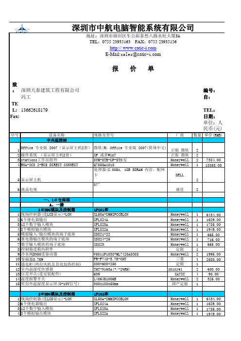
深圳市中航电脑智能系统有限公司地址:深圳市福田区车公庙泰然八路水松大厦5ATEL:0755-******** FAX:0755-********http:// E-Mail:sales@报价单致:深圳天泰建筑工程有限公司编号:冯工自:TEL:136********TEL:Fax:日期:单位:人民币(元)序号设备名称规格及型号厂商数量单价(RMB)中央监控站1Office 专业版 2007(显示屏主机2套)微软(R) Office 专业版 2007(简体中文)正版 微软22操作系统 (显示屏主机2套)XP 或者Win7正版 微软23stations工作站软件SYM-STB-UP-STN/U Honeywell27384.004BNA-2CS 2-BUS DIRECT CONNECT Q7055A1015Honeywell118858.005显示屏主机 处理器(2.0GHz, 1GB SDRAM 内存,配网卡 DELL26液晶电视37"康佳2一、1#仓库栋A、一楼1#DDC模块及控制箱1F101库1现场控制器(连LCD显示)-LON XL50A-UMMIPCCBLON Honeywell16434.0026个继电器输出XFL824A Honeywell11629.00312个数字输入模块XFL823A Honeywell11785.0048个模拟输出模块XFL822A Honeywell11949.005模拟输入/输出模块的端子底座XS821-22Honeywell1665.006继电器输出模块的端子底座XS824-25Honeywell1716.007数字输入模块的端子底座XS823Honeywell1665.008控制箱连箱内附件定做19冷水阀DN50连驱动器V5011P1038+ML7420A8088Honeywell21995.0010变频器3.7KW FR-F740-3.7K-CHT三菱12580.0011强电柜(两台风机及其电加热控制)800*600*250定做112室内温湿度传感器THT-N163A(+/-2%RH)shinyei2600.0013压差开关(连安装配件)609CATIC490.0014温度报警开关L4064K1006B Honeywell2325.0015库房外温湿度显示屏(0-10V信号)300x180x50mm国产定做12#DDC模块及控制箱1F102库1现场控制器(连LCD显示)-LON XL50A-UMMIPCCBLON Honeywell16434.0026个继电器输出XFL824A Honeywell11629.00312个数字输入模块XFL823A Honeywell11785.0048个模拟输出模块XFL822A Honeywell11949.005模拟输入/输出模块的端子底座XS821-22Honeywell1665.006继电器输出模块的端子底座XS824-25Honeywell1716.007数字输入模块的端子底座XS823Honeywell1665.008控制箱连箱内附件定做19冷水阀DN50连驱动器V5011P1038+ML7420A8088Honeywell21995.0010变频器3.7KW FR-F740-3.7K-CHT三菱12580.0011强电柜(两台风机及其电加热控制)800*600*250定做112室内温湿度传感器THT-N163A(+/-2%RH)shinyei2600.00注:1.本价格为交货不含税,含运费价格,有效期为30天。
SPX Corporation 5019 泵系统安装说明书

© SPX Corporation18101204Hex Hd. Cap Screw 192208772Lock Nut20148551Retaining Ring 21494001Mounting Bracket 223126161Swivel Hand Pump(See Form No. 101379)232514885Cap Screw 243509101Retainer 25101012Hex Hd. Cap Screw 26153162Lock Nut, Hex 272233162Flange Sleeve Bearing Parts Included but Not Shown 2180832Warning Decal 3099561Made in USA Decal 3125551Decal 3125561Warning Decal25, 26, 27Form No. 102731Parts List &Operating Instructions for:5019Item No.Part No.No.Req'd Description 12204921Trans. Mounting Plate (for Rockwell & Eaton ® RoadRanger ® transmissions; includes Items 1-4)2102083Hex Nut 3120043Washer42204083Bolt (1/2" x 1.25 Lg.)5493981Mounting Plate 6494041Special Screw 7539341Lift Weldment 8100124Socket Hd. Screw 9RS-3500-1516Hex Nut (5/16-18)111055916Hex Hd. Cap Screw 12119982Retaining Ring 133125031Pin14197772Hex Hd. Cap Screw 15112532Washer 16160024Caster17539371Jack Base FrameLow Lift Transmission JackMaximum Capacity: 2,200 Lbs.Item No.Part No.No.Req'd DescriptionShaded areas reflectthe last revisions made to this form.Jack base frames manufactured before Sept. 1997 used one 49407 bumper,two 10049 hex hd. cap screws, and two 10204 hex nuts.SPX Corporation655 Eisenhower DriveOwatonna, MN 55060-0995 USA Phone: (507) 455-7000Tech. Serv.: (800) 533-6127 Fax: (800) 955-8329Order Entry: (800) 533-6127 Fax: (800) 283-8665International Sales: (507) 455-7223 Fax: (507) 455-7063Refer to any operating instructions included with the product for detailed information about operation, testing, disassembly, reassembly,and preventive maintenance.Items found in this parts list have been carefully tested and selected by OTC.Therefore: Use only OTC replacement parts!Additional questions can be directed to the OTC Tech. Serv. Dept. at (800) 533-6127.12, 3, 456718, 191621201814, 15179, 10, 1112, 1389, 1122, 23, 24Sheet No.1 of 2Issue Date:Rev. D, 5-26-04115517190° Elbow 22204051Ram33125541Hydraulic Hose 42223961Protective Sleeve 5133441Cable Tie6119981Retaining RingParts List & Operating InstructionsForm No. 102731, Sheet 1 of 2, Back2134Part No.No.Req'd Description 1539351Ram Mounting Plate 2144382Fitting32203661Hex Screw (1-8 x 3.25 Lg.)43126161Swivel Hand PumpItem No.Part No.No.Req'd Description Item No.461235Safety PrecautionsWARNING: Failure to follow these warnings could cause a loss of load, damage to equipment, and / or failure of equipment, which may result in personal injury or property damage:•If the operator cannot read English, operating instructions and safety precautions must be read and discussed in the operator’s native language.•Wear eye protection that meets the requirements of ANSI Z87.1 and OSHA standards.•Before each use, inspect the jack for leaks and damaged, loose, or missing parts. Immediately replace cut, frayed, or damaged hoses.•Do not modify this transmission jack or use attachments unless supplied by OTC. If a modification is needed, please contact OTC Technical Services.•This jack is designed to remove or install only automotive or truck transmissions. Using the jack in a manner for which it is not designed may result in injury or damage to equipment.•The load must not exceed the maximum rated capacity of 2,200 lbs.•Stay out from underneath the load at all times.•Secure the load to the jack.•Use the jack on hard, level surfaces only.•Lower the load completely before moving the jack.Assembly Instructions1.Assemble the handle to the pump by aligning the holes in the handle withthe holes in the pump cap and piston. Slide a pin through each hole, and secure each pin with a retaining ring on each end. See Figure 1.2.For use with a Rockwell or Eaton ® RoadRanger ® truck transmission:Place the transmission mounting plate (220492) on top of the white mounting plate (49398) as shown in the parts list drawing. Insert bolts (220408) through the three holes in the plates. Secure the bolts by attaching a washer (12004) and nut (10208) to each bolt from underneath the plates.Figure 1© SPX CorporationParts List & Operating InstructionsForm No. 1027311.Position the jack under the transmission.2.Close the control valve. Operate the pump handle to raise the boom and align the mounting plate with thetransmission. See Figure 2.3.Remove the transmission according to the instructions in the vehicle service manual.4.Position the transmission on the mounting plate, resting against the angle plates as shown in Figure 2.•The transmission mounting plate may be tilted forward and backward by adjusting the linkage arm (49404).•The transmission mounting plate may be tilted side-to-side by adjusting the hex hd. cap screws (10120).5.Secure the transmission to the mounting plate.6.Lower the load by slowly opening the control valve. Use the control valve to regulate how fast the boom is lowered.Optional Equipment - OTC AdjustaGrip ® Universal Mounting Arm (305811)OTC's universal mounting arms may be used to mount other large transmissions to the low lift transmission jack. (Order part no. 305811 for one universal mounting arm;order each arm separately.)1.Remove the transmission mounting plate (220492), bolts (220408), washers(12004), and hex nuts (10208).2.Fasten the universal mounting arms to the top of the mounting plate (49398)using the washers and nuts provided. See Figure 3.a.Loosen all the joints in the adjust-a-grip arms.b.Locate the right angle mounting ear of each arm over a slot in the mountingplate, and install a washer and nut.c.Use cap screws to attach at least two of the arms to the transmission.Operating InstructionsFigure 2The transmission must rest against the angle plates as shown.Right Angle Mounting EarMounting Plate (49398)Figure 3Angle PlatesAngle PlateSheet No.2 of 2Issue Date:Rev. D, 5-26-04Maintenancepletely lower the jack any time it is not being used.2.The hydraulic pump and ram assembly should be drained, flushed, and refilled with oil at least once each year. Usea high grade hydraulic oil such as OTC #9036 or an equivalent (215 SUS viscosity rating at 100° F).3.Lubricate caster swivel plates and wheels every six months using pressure gun grease.4.Lubricate lift arm pivot points as needed with SAE 30 motor oil.Sheet No.of 1Issue Date:4-25-94Litho in USA1Parts List Form No. 101386, Sheet of , Back1 1SINGLE STAGE HYDRAULIC HAND PUMP Form No. 101379312616Parts List for:Litho in USA12345678910111221314151617181920212223242526Sheet No. 1 of 2Rev. 2Date: 11 Nov. 1996SPX Corporation655 Eisenhower Drive Owatonna, MN 55060-0995 USA Phone: (507) 455-7000Tech. Services: (800) 533-6127 Fax: (800) 955-8329Order Entry: (800) 533-6127 Fax: (800) 283-8665 International Sales: (507) 455-7290 Fax: (507) 455-7063Parts List, Form No. 101379, Back sheet 1 of 2Item Part No.No.No.Req’d Description1104271Pipe Plug (1/8 NPTF)22514889Flat Head Screw (1/4-20 UNC x 5/8 Lg.;Torque to 95/105 in. lbs.)33509061Mounting Plate42117434Retaining Ring (Note: Expand the retaining ring to.440 max. during installation.)52117422Dowel Pin6100021Cap Screw (1/4-20 UNC X 3/8 Lg.)7127191Washer (For 1/4 Bolt)82117691Handle Grip961806WH21Handle103508681Reservoir Assembly112515441Tie Rod (Note: Screw in tie rod until itbottoms out in pump body.)122515571Piston Assembly13*150921Rod Wiper14584841Pump Body Cap153509101Retainer16*2139871Backup Washer (11/16 X 1/2 X 3/64, -112;Assemble with concave surface toward o-ring.)17*102711O-ring (11/16 X 1/2 X 3/32, -112)18*103781Steel Ball (3/8 dia.)19*125571O-ring (11/32 X 7/32 X 1/16, -009)20*2114951O-ring (2-11/16 X 2-1/2 X 3/32, -144)21*2150751Filter2221278-751Relief Valve Assembly (Set at 7,600/8,200 PSI)23*3059771Warning Decal24*2127391O-ring (square)25102041Hex Nut (3/8-16 UNC; Torque to 230/250 in. lbs.)26527111Reservoir CapPart numbers marked with an asterisk (*) are contained in Repair Kit No. 300668.NOTE: Shaded areas reflect last revision(s) made to this form.Parts ListForm No. 101379SECTION VIEWS12159071Decal23059751Valve Screw(Torque to 350/370 in. lbs.)3*104442Compression Spring(3/16 I.D. X 13/32 Lg.)4*103781Steel Ball (3/8 dia.)5*2117971Compression Spring(5/32 O.D. X 5/8 Lg.)6*103751Steel Ball (1/4 dia.)7232731Regulator Valve with Knob 8645851Pump Body9109701Pipe Plug (1/4 NPTF)10148741Copper Washer (.700 X 1/2 X 1/32)1234356789Part numbers marked with an asterisk (*) are contained in Repair Kit No. 300668.Item Part No.Item Part No.No.No.Req’d Description No.No.Req’d Description10Note: Shaded areas reflect last revision(s) made to this form.Sheet No. 2 of 2Rev. 2Date: 11 Nov. 1996。
器材价格参考用

器材价格参考⽤部分品牌参考价格此处的价格仅供参考,多为⼚家报价,⽬的是给⼤家⼀个⼤致价位的概念(转贴于影⾳新时代论坛alexking)按器材类型分类雅马哈(YAMAHA)报价:YAMAHA AZ1 13500YAMAHA AZ2 7500YAMAHA 2400 6400YAMAHA 1400 4900YAMAHA 750 3950YAMAHA 650 3900YAMAHA 450 2000YAMAHA 640 3400YAMAHA 540 2450YAMAHA 440 2100YAMAHA 340 1580YAMAHA RXV-596 AV机 2800⼈民币YAMAHA RXV-800 AV机 3900⼈民币YAMAHA RXV-1000 AV机 4600⼈民币YAMAHA A1 AV机 13200⼈民币YAMAHA A2 AV机 8800⼈民币马兰⼠(MARANTZ)报价:MARANTZ 7400 5100MARANTZ 7300 4900MARANTZ 6400 3800MARANTZ 6300 3500MARANTZ 5400 3200MARANTZ 5300 2700MARANTZ 4400 2100MARANTZ 4300 1980马兰⼠ SR5200 AV机 3800⼈民币马兰⼠ SR6200 AV机 4500⼈民币马兰⼠ SR7200 AV机 5700⼈民币马兰⼠ SR8000 AV机 7400⼈民币马兰⼠ SR4200 AV机 3200⼈民币马兰⼠ PM14SA 合并机 14500⼈民币马兰⼠ PM14 合并机 10500⼈民币马兰⼠ PM17SA 合并机 8500⼈民币马兰⼠ PM17 合并机 6800⼈民币天龙(DENON)报价:DENON 3805 9480DENON 3803 7800DENON 2803 5800DENON 1804 3850DENON 1604 2700DENON 1404 2250天龙 S10III 合并机 13500⼈民币天龙 PMA-2000 合并机 6500⼈民币天龙 PMA-1500 合并机 4200⼈民币天龙 AVC-A10SE AV机 11500⼈民币天龙 AVR-1801 AV机 4200⼈民币天龙 AVR-2800 AV机 5800⼈民币天龙 AVR-3300G AV机 6800⼈民币天龙 AVR-3801 AV机 7500⼈民币安桥(ONKYO)报价:ONKYO TX-NR901 12480ONKYO TX-NR801 9280ONKYO TX-SR701 5300ONKYO TX-SR601 3700ONKYO TX-SR501 2700ONKYO TX-SR401 210021CN A50SE 合并机 5200⼈民币21CN A100 合并机 5080⼈民币21CN A45 合并机 3480⼈民币21CN A80 合并机 3000⼈民币21CN A120 合并机 2280⼈民币雅乐普契尼 5460⼈民币雅乐普契尼特别版 7560⼈民币雅乐普契尼签名版 6650⼈民币雅乐普契尼签名特别版 9240⼈民币雅乐贝⾥尼前级 8200⼈民币雅乐唐采尼帝后级 10000⼈民币丹麦皇⼦ B-100 合并机 9000⼈民币架势Classe CAP151 合并机 16000⼈民币⼒⼠ C-509S 合并机 39560⼈民币⼒⼠ C-7I 前级 35500⼈民币⼒⼠ M-7I 后级 35500⼈民币⼒⼠ C-3 前级 12880⼈民币⼒⼠ M-3 后级 14620⼈民币⼒⼠ C-9II 前级 85380⼈民币⼒⼠ B-10 后级 75520⼈民币Krell 300i 合并机 18000⼈民币Krell 500i 合并机 34000⼈民币TAG Mc Laren 60i 合并机 7000⼈民币TAG Mc Laren 60ai 合并机 9800⼈民币翩美 Primare A30.1合并机 15800⼈民币翩美 Primare A20 合并机 9300⼈民币翩美 Primare A10 合并机 7500⼈民币Mark Levinson No383 合并机 50000⼈民币乐林 Concentra 合并机 36000⼈民币Linn kolektor 前级 7200⼈民币Linn LK85 后级 7200⼈民币Bryston 4B ST 后级 21300⼈民币Bryston 7B ST 后级 37000⼈民币Bryston BP25 前级 17000⼈民币⾳乐之旅ECP1前级 5400⼈民币⾳乐之旅EC4.5前级 7860⼈民币⾳乐之旅EC4R前级 11700⼈民币⾳乐之旅EC4.7前级 19630⼈民币⾳乐之旅AW600FTT后级 9650⼈民币⾳乐之旅AW100DMB后级 17200⼈民币⾳乐之旅AW120DMB后级 26620⼈民币⾳乐之旅AW180M后级 24600⼈民币⾳乐之旅ECI1合并机 16670⼈民币⾳乐之旅ECI2合并机 6350⼈民币⾳乐之旅ECI3合并机 12192⼈民币NAD S-300 合并机 12500⼈民币NAD S-100 前级 9000⼈民币NAD S-200 后级 12000⼈民币ONIX A-120 合并机 5500⼈民币ONIX A-60 合并机 3600⼈民币ONIX OA-80 合并机 4000⼈民币ONIX 3000+2150前后级 7500⼈民币⾳乐传真 X-A1 合并机 8500⼈民币⾳乐传真 A-3 合并机 12000⼈民币⾳乐传真 A-300 合并机 17000⼈民币⾳乐传真 M3 合并机 38000⼈民币麦景图 MC352 后级 63800⼈民币麦景图 MC300 后级 43000⼈民币麦景图 C15 前级 16500⼈民币麦景图 MA6450 合并机 22000⼈民币麦景图 MA6850 合并机 30000⼈民币多能⼠ TIA-2300 合并机 12800⼈民币⾦嗓⼦ E407V 合并机 33000⼈民币⾦嗓⼦ E306V 合并机 22000⼈民币⾦嗓⼦ E211 合并机 13800⼈民币Bow 丹麦神⼸ Wazoo 合并机 23000⼈民币雅骏 FMJ A22 合并机 16000⼈民币Gryphon Callisto2200 合并机 33000⼈民币Gryphon Callisto2100 合并机 27000⼈民币Gryphon Century 合并机 28000⼈民币Gryphon TABU AT 合并机 22000⼈民币Goldmund SRI-2 合并机 30000⼈民币⾳箱报价-----------------达尼皇太⼦II 5600⼈民币 AE 100iLE 2500⼈民币达尼 ROYAL SCEPTER 8400⼈民币 AE 109LE 4500⼈民币达尼皇太⼦370 7700⼈民币 AE 120 6350⼈民币达尼皇太⼦470 12300⼈民币 AE 107C(中置) 1930⼈民币达尼皇太⼦870 17500⼈民币 AE 108S(超低⾳) 4345⼈民币达尼 ASXCENTER 1250⼈民币 AE 200 3850⼈民币达尼 ASX 1000 1400⼈民币 AE 209 5860⼈民币达尼 ASX 3000 2500⼈民币 AE 1 12360⼈民币达尼 ASX 5000 3750⼈民币 AE 2 19300⼈民币达尼 ASX 8000 5300⼈民币 AE 1(签名版) 26300⼈民币达尼男爵 505 4800⼈民币 AE 2 (签名版) 46600⼈民币达尼男爵 606 6000⼈民币 AE 5 99200⼈民币达尼男爵 808 7400⼈民币 AE 509 11860⼈民币达尼⼦爵 SUITE 1.5 6400⼈民币 AE 520 15330⼈民币达尼⼦爵 SUITE 2.5 8700⼈民币 AE ⽔晶⼀号 1960⼈民币达尼⼦爵 SUITE 3.5 12700⼈民币 AE ⽔晶⼆号 2960⼈民币达尼⼦爵中置 3500⼈民币 法国三⾓牌 TITUS-TZX 4800⼈民币达尼⼦爵超低⾳ 4300⼈民币 法国三⾓牌 COMETE-TZX 6100⼈民币雅丽丝 1号⾳箱 18800⼈民币 法国三⾓牌 LUNN 6800⼈民币雅丽丝 2号⾳箱 28800⼈民币 法国三⾓牌 ZEPHYR 9000⼈民币KEF CRESTA 1 ⾳箱 1900⼈民币 法国三⾓牌 ITTOHxs 11600⼈民币KEF CRESTA 2 ⾳箱 2600⼈民币 法国三⾓牌 ANTAL 12400⼈民币威武极典 Solus 16000⼈民币 法国三⾓牌 ZAYS MKII 22000⼈民币威武时尚谱乐 14500⼈民币 法国三⾓牌 EXTAN 34000⼈民币威武时尚百乐 11000⼈民币 法国梦幻之声 Initiation 1 2340⼈民币威武时尚意乐 5000⼈民币 梦幻之声 Initiation 2 3900⼈民币Spendor S2 4536⼈民币 梦幻之声 Initiation 3 5200⼈民币Spendor 2020 3460⼈民币 梦幻之声 Initiation 4 3280⼈民币Spendor 2030 4950⼈民币 梦幻之声 Initiation 6 3770⼈民币Spendor 2040 7730⼈民币 梦幻之声 Initiation 7 5200⼈民币Spendor SP3/1P(红⽊) 9185⼈民币 梦幻之声 Initiation 中置 1800⼈民币Spendor SP1/2(桃⽊) 14184⼈民币 丹拿听众42 5500⼈民币美之声监听⼀号 3800⼈民币 丹拿听众52 6500⼈民币美之声监听三号 4780⼈民币 丹拿听众62 8000⼈民币美之声焦点⼗号 1270⼈民币 丹拿听众72 11000⼈民币美之声和谐三号 2720⼈民币 丹拿听众82 14000⼈民币美之声梦幻三号 3780⼈民币 丹拿 CONTOUR1.1MKII 9800⼈民币B&W N805 14000⼈民币 丹拿 CONTOUR1.3MKII 13500⼈民币B&W N804 28000⼈民币 丹拿 CONTOUR1.3SE 22000⼈民币B&W N803 35000⼈民币 丹拿 CONTOUR1.8MKII 20000⼈民币B&W CDM1NT 8800⼈民币 ProAc T2000 7600⼈民币B&W CDM7NT 14000⼈民币 ProAc T2000 签名版 9600⼈民币B&W CDM1SE 6800⼈民币 ProAc 1SC 11600⼈民币卓丽贵族世代⼀号 13500⼈民币 西湖 LC6.75 13200⼈民币皇冠鉴名三号MKII 13500⼈民币 西湖 LC5.75 9600⼈民币---------------------CD机和咸菜报价-----------------------CD机---马兰⼠ CD6000OSE CD机 2550⼈民币马兰⼠ CD19A CD机 4000⼈民币马兰⼠ CD17DA CD机 5400⼈民币马兰⼠ CD16D CD机 7000⼈民币天龙 DCD-S10II CD机 9600⼈民币天龙 DVD5000 DVD机 14500⼈民币天龙 DVD1000 DVD机 3300⼈民币雅乐巴格⾥尼 CD机 7500⼈民币NAD S500 CD机 9500⼈民币君⼦⾏星 CD机 7200⼈民币⼒⼠ D-600S CD机 12880⼈民币⼒⼠ D-7 CD机 25640⼈民币雅骏 FMJ CD23 CD机 16000⼈民币CARY CD303 CD机 7000⼈民币CARY CD306 CD机 19700⼈民币架势Classe CDP.3II CD机 12800⼈民币先锋 DV-3300 DVD机 1780⼈民币先锋 DV-S10A DVD机 15800⼈民币先锋 DV-S6D DVD机 6800⼈民币美国雅卓 UCD-100 CD机 6500⼈民币美国雅卓 HDCD-10 解码器 5500⼈民币TEAC 25XS CD机 9100⼈民币TEAC 50X CD机 13500⼈民币SONY SCD-1 SACD机 30000⼈民币SONY SCD-777ES SACD机 19500⼈民币SONY SCD-555ES SACD机 13500⼈民币SONY DVP-9000ES DVD机 12500⼈民币SONY CDP-XA7ES CD机 14500⼈民币SONY CDP-55ES CD机 7500⼈民币翩美 1.0 DVD机 11000⼈民币---咸菜---NBS STINGHER1mRCA信号线1050⼈民币NBS DRAGON/FLY ⼩飞龙系列:1m RCA 信号线1550⼈民币1.5m RCA 信号线2000⼈民币1m XLR 信号线1995⼈民币1.5m XLR 信号线2500⼈民币2.5m ⾳箱线2400⼈民币3m ⾳箱线2900⼈民币1.5m 电源线 1500⼈民币NBS MINE/SERPENT-II ⼩蛇系列:1m RCA 信号线2350⼈民币1.5m RCA 信号线2960⼈民币1m XLR 信号线2800⼈民币1.5m XLR 信号线3600⼈民币2.5m ⾳箱线3100⼈民币3m ⾳箱线3200⼈民币1.5m 电源线 2400⼈民币NBS SERPENT-II中蛇系列: 1.5m RCA 信号线4500⼈民币2m RCA 信号线5500⼈民币1.5m XLR 信号线4500⼈民币2m XLR 信号线5500⼈民币1.5m 电源线 3000⼈民币NBS KING/SERPENT-II蛇王系列:1.5m RCA 信号线7900⼈民币2m RCA 信号线9600⼈民币1.5m XLR 信号线7900⼈民币2m XLR 信号线9600⼈民币2.5m ⾳箱线10000⼈民币3m ⾳箱线12000⼈民币NBS SIGNATURE-II签名系列:1.5m RCA 信号线9600⼈民币2m RCA 信号线12000⼈民币1.5m XLR 信号线9600⼈民币2m XLR 信号线12000⼈民币2.5m ⾳箱线14400⼈民币3m ⾳箱线16000⼈民币1m 电源线 4000⼈民币MASTER-II⼤师系列:AQ Coral⽔蟒 1m XLR1140⼈民币1.5m RCA 信号线12000⼈民币2m RCA 信号线18000⼈民币1.5m XLR 信号线12000⼈民币2m XLR 信号线18000⼈民币2.5m ⾳箱线26000⼈民币3m ⾳箱线33000⼈民币1m 电源线 5800⼈民币注意: NBS ⼩蛇以下报价偏⾼,只供参考。
Lincoln TTOMAHAWK 625 操作手册说明书

T OMAHAWK ™625OPERATORʼS MANUALIM10020January, 2012Safety Depends on YouLincoln arc welding and cutting equipment is designed and built with safety in mind. However,your overall safety can be increased by proper installation ... and thoughtful operation on your part. DO NO T INSTALL,O PERATE O R REPAIR THIS EQUIPMENT WITHO UT READ-ING THIS MANUAL AND THE SAFETY PRECAUTIO NS CO N-TAINED THRO UGHO UT.And,most importantly, think beforeyou act and be careful.NOTESvfor selecting a QUALITY product by Lincoln Electric. We want you to take pride in operating this Lincoln Electric Company product ••• as much pride as we have in bringing this product to you!Read this Operators Manual completely before attempting to use this equipment. Save this manual and keep it handy for quick reference. Pay particular attention to the safety instructions we have provided for your protection.The level of seriousness to be applied to each is explained below:HIGH FREQUENCY INTERFERENCE PROTECTIONThe TOMAHAWK™ 625 employs a touch start mech-anism for arc initiation which eliminates high frequen-cy emissions from the machine as compared with spark gap and solid state type high frequency genera-tors. Keep in mind, though, that these machines may be used in an environment where other high frequen-cy generating machines are operating. By taking the following steps, high frequency interference into the TOMAHAWK™ 625 can be minimized(1)Make sure the power supply chassis is connectedto a good earth ground. The work terminal ground does NOT ground the machine frame.(2)Keep the work clamp isolated from other workclamps that have high frequency.(3)If the work clamp cannot be isolated, then keepthe clamp as far as possible from other work clamp connections.(4)When the machine is enclosed in a metal building,several good earth driven electrical grounds around the periphery of the building are recom-mended.Failure to observe these recommended installation procedures may cause improper function of the TOM-AHAWK™ 625 or possibly even damage to the control system or power supply components.INPUT ELECTRICAL CONNECTIONS The TOMAHAWK™ 625 is rated for 208VAC and 230VAC input voltage. Before installing the machine, check that input supply voltage, phase, and frequency are the same as the machine's voltage, phase, and frequency as specified on the machine's rating plate.• The TOMAHAWK™ 625 should be connected only by a qualified electrician. Installation should be made in accordance with local codes.For use on engine drives, keep in mind the above input draw restrictions and the following precaution. The TOMAHAWK™ 625 can be operated on engine driven generators as long as the 230 volt auxiliary meets the following conditions:• The AC waveform peak voltage is below 400 volts.• The AC waveform frequency is between 45 and 65 Hz.• The RMS voltage of the AC waveform is always greater than 208VAC.USER RESPONSIBILITYBecause design, fabrication, erection and cutting vari-ables affect the results obtained in applying this type of information, the serviceability of a product or struc-ture is the responsibility of the user. Variation such as plate chemistry, plate surface condition (oil, scale), plate thickness, preheat, quench, gas type, gas flow rate and equipment may produce results different than those expected. Some adjustments to procedures may be necessary to compensate for unique individ-ual conditions. Test all procedures duplicating actual field conditions.DESIGN FEATURES AND ADVANTAGESThe TOMAHAWK™ 625 design makes plasma cutting uncomplicated. This list of design features and advan-tages will help you understand the machine's total capabilities so that you can get maximum use from your machine.- Light weight and portable design for industrial use. - Continuous control, 10 - 40 amps.- Reliable touch start mechanism for plasma arc initi-ation.- Rapid arc restrike for fast cutting of expanded metal. - Input over voltage protection.- Bright 3.0 second timed pilot arc.- Purge section on output dial.- Air regulator and pressure gage included.- Internal water separator included.- Parts-in-Place mechanism to detect proper installa-tion of consumables and torch.- Preflow/Postflow timing. Preflow is eliminated if arc is re-initiated in Postflow.- Thermostatic Protection.- Solid state over-current protection.- Unique electrode and nozzle design for optimum cooling and long life.CUTTING CAPABILITYThe TOMAHAWK™ 625 is rated at 40 amps, at 35% duty cycle on a 10 minute basis. If the duty cycle is exceeded, a thermal protector will shut off the output of the machine until it cools to the normal operating temperature.Figure B.1 shows the cut capacity of the TOMA-HAWK™ 625 when cutting mild steel. (The graph plots cut thickness vs. torch travel speed with a torch standoff of 0.15".) CONSUMABLE LIFEThe expected life for the TOMAHAWK™ 625's elec-trode under normal operating conditions is approxi-mately 1000 starts/cuts. An erosion of .060" is typical for end of electrode life, however, the electrode life may last longer. A green and erratic arc will indicate definite electrode failure and the electrode should be replaced immediately.It is recommended that consumables be replaced in complete sets. (Example: Electrode and Nozzle). This will maximize the performance of the TOMAHAWK™625 system.Figure B.1 TOMAHAWK 625LIMITATIONSDo not exceed output current and duty cycle rating of machine. Do not use the TOMAHAWK™ 625 for pipe thawing.If the arc turns off while cutting using low input volt-age, that is below 208V, lower the air pressure by adjusting the regulator knob.When using with the Outback 180, gouging is not rec-ommended.Turn the machine's ON/OFF POWER SWITCH to the OFF position.• Connect the air supply to the machine.• Turn the main power on and the machine power switch to the ON position.- The fan will start.- The pre-charge circuit will operate for 3 seconds,then the green "Power" LED will illuminate.• Attach the work lead clamp to the workpiece before cutting.• Set the output current control knob to maximum position for higher cutting speed and less dross for-mation. Reduce the current, if desired to reduce the kerf (cut) width, heat affected zone, or travel speed as required.Note:If the circuit breaker trips while cutting at high-er amperages - reduce the cutting amperage on the unit, or provide an input circuit with higher current capacity.• Rotate the output knob into the purge zone to check or set the gas pressure. Pull the pressure regulator cap out and turn it to set the pressure.- Adjust the gas regulator for 75-80 PSI (0.50-0.55MPa).- Turn the output knob out of the purge zone.- The gas will immediately turn off. The pressure gage may show an increase in pressure after the air turns off but this is normal. Do NOT reset the pressure while the air is NOT flowing.PROCEDURE RECOMMENDATIONSWhen properly used, plasma arc cutting is a very eco-nomical process. Improper use will result in a very high operating cost.General - In All Cases• Follow safety precautions as printed throughout thisoperating manual and on the machine.• If piercing is required, slowly lower the torch at anangle of about 30° to blow the dross away from the torch tip and slowly rotate the torch to a ver-tical position as the arc becomes deeper. This process will blow a lot of molten metal and dross. Be careful! Blow the dross away from the torch, the operator and any flammable objects.• The nozzle should not be dragged on the metal surface. A drag spacer is provided to maintain a consistant touch height. Refer to Touch Parts Configurations in this Section.• Where possible, start the cut from the edge of thework piece.• Keep moving! A steady speed is necessary. Donot pause.• Replace the nozzle when the orifice exit is eroded away or oval shaped.• After the problem is found, or if there is nothing apparently wrong, reset the machine by turning the power switch OFF and then ON again. (It is possi-ble for electrical noise to trip the safety circuit on rare occasions. This should not be a regular occur-rence.)• If the machine does not reset or continues to trip,consult the Troubleshooting Section.• Use the proper cutting procedures referred to in Procedure Recommendations.PILOT ARC DISCUSSIONThe TOMAHAWK™ 625 has a smooth, continuous pilot arc. The pilot arc is only a means of transferring the arc to the workpiece for cutting. Repeated pilot arc starts, in rapid succession, is not recommended as these starts will generally reduce consumable life.Occasionally, the pilot arc may sputter or start inter-mittently. This is aggravated when the consumables are worn or the air pressure is too high. Always keep in mind that the pilot arc is designed to transfer the arc to the workpiece and not for numerous starts without cutting.The TOMAHAWK™ 625 does not utilize high frequen-cy starting. When the pilot arc is started, a slight impulse will be felt in the torch handle. This occur-rence is normal and is the mechanism which starts the plasma arc. This impulse can also be used to help troubleshoot a "no start" condition.Suggestions for Extra Utility from the TOMAHAWK™ 625 System:1. Occasionally an oxide layer may form over the tip of the electrode, creating an insulating barrier between the electrode and nozzle. This will result in the tripping of the TOMAHAWK™ 625's safety circuit. When this happens turn the power off,remove the nozzle and electrode and use the elec-trode to rub against the inside bottom surface of the nozzle. This will help remove any oxide buildup. Replace the nozzle, turn on the power and continue cutting. If the safety circuit continues to trip after cleaning the consumables, then replace them with a new set. Do not continue to try and cut with excessively worn consumables as this can cause damage to the torch head and will degrade cut quality. Do not allow torch cable or body to contact hot surface.2. To improve consumable life, here are some sug-gestions that may be useful:• Make sure the air supply to the TOMAHAWK™625 is clean and free of oil. Use several extra in line filters if necessary.• Minimize dross buildup on the nozzle tip by starting the cut from the edge of the plate when possible.• Pierce cutting should be done only when nec-essary. If piercing, angle torch about 30° from the plane perpendicular to the work piece,transfer the arc, then bring the torch perpendic-ular to the work and begin parallel movement.• Reduce the number of pilot arc starts without transferring to the work.• Reduce the pilot arc time before transferring to the work.• Set air pressure to recommended setting. A higher or lower pressure will cause turbulence in the plasma arc, eroding the orifice of the nozzle tip.• Use only Lincoln consumable parts. These parts are patented and using any other replace-ment consumables may cause damage to the torch or reduce cut quality.TORCH PART CONFIGURATIONSThere are different torch configurations depending onthe cutting or gouging application.Standard Cutting Setup:In the Standard Cutting configuration the nozzle isdesigned not to touch the work piece. The advantageof this cutting method is good visibility of the arc.However it requires a steady hand to avoid touchingthe nozzle to the work piece which will cause prema-ture nozzle wear and a jagged cut. An optional dragspacer can be attached to the retaining cap to main-tain a consistent arc height.Contact Cutting Setup:Contact Cutting uses special expendable parts thatallow the torch to touch the work piece. The advan-tage of contact cutting is that the torch can touch thework piece, steadily dragging it across the surface.The disadvantage of contact cutting is the plasma arcis not as visible as with a standard torch set-up. Sincethis machine cuts at 40 amps or less it uses the directcontact torch configuration which allows a special noz-zle to come in contact with the work piece.Gouging Setup:If gouging metal and not cutting completely through the part is required, a special gouging nozzle is used in conjunction with a gouge shield to protect the noz-zle from molten metal blow back.Refer to the torch parts decal located on your machine or the parts pages at the back of this manual for the specific part numbers required for each of these setups.ALWAYS USE GENUINE LINCO LN ELECTRIC ELECTRO DES, NO ZZLES, AND EXPENDABLE PARTS FO R THE BEST CUTTING PERFO R-MANCE.GENERAL OPTIONS /ACCESSORIESThe following options/accessories are available for your Tomahawk Plasma cutter from your local Lincoln Distributor.K2377-1-Small Canvas CoverProtect your machine when not in use. Made from attractive red canvas that is flame retardant, mildew resistant and water repellent. It includes a convenient side pocket to hold the plasma torch.K2886-1- Plasma Circle Cutting KitFor cutting circles from 3” to 33” in diameter (77mm to 838mm).TORCHESThe following replacement torch is available:K2847-1 LC40 Handheld Plasma Torch 20' (6m) EXPENDABLE PARTSRefer to the torch parts decal located on your machine or the parts pages at the back of this manual for the specific part numbers required for each of the avail-able setups.This Troubleshooting Guide is provided to help you locate and repair possible machine malfunctions. Simply follow the three-step procedure listed below.Step 1.LOCATE PROBLEM (SYMPTOM).Look under the column labeled “PROBLEM (SYMPTOMS)”. This column describes possible symptoms that the machine may exhibit. Find the listing that best describes the symptom that the machine is exhibiting. Step 2.POSSIBLE CAUSE.The second column labeled “POSSIBLE CAUSE” lists the obvious external possibili-ties that may contribute to the machine symptom.Step 3.RECOMMENDED COURSE OF ACTIONThis column provides a course of action for the Possible Cause, generally it states to contact you local Lincoln Authorized Field Service Facility.If you do not understand or are unable to perform the Recommended Course of Action safely, contact you local Lincoln Authorized Field Service Facility.STATUS BOARD INDICATORSJapaneseChineseKoreanArabicREAD AND UNDERSTAND THE MANUFACTURER’S INSTRUCTION FOR THIS EQUIPMENT AND THE CONSUMABLES TO BE USED AND FOLLOW YOUR EMPLOYER’S SAFETY PRACTICES.SE RECOMIENDA LEER Y ENTENDER LAS INSTRUCCIONES DEL FABRICANTE PARA EL USO DE ESTE EQUIPO Y LOS CONSUMIBLES QUE VA A UTILIZAR, SIGA LAS MEDIDAS DE SEGURIDAD DE SU SUPERVISOR.LISEZ ET COMPRENEZ LES INSTRUCTIONS DU FABRICANT EN CE QUI REGARDE CET EQUIPMENT ET LES PRODUITS A ETRE EMPLOYES ET SUIVEZ LES PROCEDURES DE SECURITE DE VOTRE EMPLOYEUR.LESEN SIE UND BEFOLGEN SIE DIE BETRIEBSANLEITUNG DER ANLAGE UND DEN ELEKTRO-DENEINSATZ DES HERSTELLERS. DIE UNFALLVERHÜTUNGSVORSCHRIFTEN DES ARBEITGEBERS SIND EBENFALLS ZU BEACHTEN.JapaneseChineseKoreanArabicLEIA E COMPREENDA AS INSTRUÇÕES DO FABRICANTE PARA ESTE EQUIPAMENTO E AS PARTES DE USO, E SIGA AS PRÁTICAS DE SEGURANÇA DO EMPREGADOR.• Sales and Service through Subsidiaries and Distributors Worldwide •Cleveland, Ohio 44117-1199 U.S.A. TEL: 216.481.8100 FAX: 216.486.1751 WEB SITE: 。
外形小巧AV对对碰
外形小巧AV对对碰
小洛
【期刊名称】《电脑与电信》
【年(卷),期】2000(0)12
【摘要】假日正是郊游玩乐的好时节,沿途听歌、照相、拍Video自是少不免,一身轻便装束加上小巧多功能的AV良伴,助你旅途更轻松愉快。
【总页数】2页(P100-101)
【关键词】数码相机;资料传送;自动关机;MP3格式;轻松愉快;制造商;录音;像素;恩物;字源
【作者】小洛
【作者单位】
【正文语种】中文
【中图分类】TN948.41
【相关文献】
1.小巧外形功能强惠普CP1025评测 [J],
2.Q萌外形,时尚小巧的毛孔清洁器——洗脸洁面仪 [J], 侯婷婷
3.小巧的外形,灵活多变的画幅,让小房间投影同样精彩白雪(SnowWhite)SM072SQH [J], 伟峰
4.外形小巧但功能强大:超小型放大器在复杂系统设计中展现优异性能 [J],
5.Diodes推出150 mA低压差稳压器为电池供电便携式器材带来低噪声和小巧外形 [J],
因版权原因,仅展示原文概要,查看原文内容请购买。
上海天能凝胶图像处理系统1600说明书
Tanon-1600 凝胶图像处理系统
2 软件安装
2.1 软件的安装
注意:请确保您的系统是 Windows 2000 或 Windows XP 系统。 1. 将软件狗安装在计算机的打印机端口上。 2. 将安装光盘放入计算机,光盘将自动启动安装程序。(如未能启动,可运行光盘目录下的
Install.exe 文件) 3. 点击“安装加密锁驱动程序”,均选择“继续”,请勿改变默认选项。 4. 安装 GIS、DOTS、COLON 软件。(默认安装为 D 盘)
1.4 Tanon-1600 数码凝胶系统的计算机要求
具有 USB 2.0 接口的 PC 电脑 P3 以上的芯片 Windows XP/2000 中文操作系统 CD-ROM 光驱 128 M 以上的内存 10G 以上的硬盘空间
1.5 Tanon-1600 数码凝胶图像分析系统售后服务
Tanon-1600 数码凝胶图像分析系统保修壹年; Tanon-1600 用户可免费升级 Tanon 凝胶成像系统相关软件。
帮助菜单名称作用帮助打开帮助文件关于查看软件版本及相关信息图标名称作用打开打开图像保存保存图像加注文件打印打印图像方框添加方框圆圈添加圆圈箭头添加箭头文字添加文字删除删除所选取的加注项全部删除删除全部加注项常用参数设置可设置常用的使用参数确认后关闭标注以后再重新打开标注功能时可自动按已设置的条件进行标注颜色选取线条颜色线宽选取线条宽度tanon1600凝胶图像处理系统11工具栏说明图标名称作用打开文件打开分析图像保存保存图像打印打印图像视频打印以视频接口打印图像twain设备输入启动twain接口的仪器ccd拍摄打开ccd拍摄界面移动当图像超过屏幕时移动图像图像放大放大图像图像缩小缩小像图像回复原图恢复图像至原始大小灰度调整调整图像的亮度对比度系数图像反转图像颜色黑转白白转黑类似于制作底片局部图像选取切割出部分图像生成新的图像自动泳道选择计算机自动判别泳道条带手动泳道选择以手工方式选择泳道条带pcr分析人工指定区域内计算出该条带区域条带数值大于该背景值的数据数据显示分析时打开数据窗口显示曲线分析时打开泳道曲线窗口分子量进行分子量的分析标准量进行标准量含量的分析定位线显示分析时图像曲线对应线背景选择选取图像背景颜色泳道宽度调整调整泳道分析框宽度使所分析的泳道在分析框条带阈值调整调整条带判断灵敏度快捷菜单说明在分析图像时单击鼠标右键会出现快捷菜单注
早期国产相机——仙乐照相机
——仙乐照相机早期国产相机一、溯源“仙乐”照相机2004年7月3日,上海华侨摄影协会相机收藏研究会主办的《相机收藏研究》报第27期一版刊载祖忠人文章《洗去历史尘埃重现早期国产相机制造一幕——追寻生产“仙乐”相机的历史真相》。
二版刊载夏复华文章《一款早期国产方镜箱相机现身沪上》、郑德辅文章《补正中国相机春天的追思——兼忆我的父亲郑崇兰》。
三篇文章全方位报道了“仙乐”照相机的来龙去脉(图1)。
研究会发现“仙乐”相机后,追根溯源,找到了郑崇兰先生之子郑德辅,维纳氏电影照相器材厂资方代理人高式熊、员工郑学惠、朱纪成、陈福慰,以及研究会祖忠人、赵振新、夏复华、吴曾乐、徐光化等人,他们在中华相机史料博物馆进行了追述与求证(图2)。
据郑学惠先生回忆,当年在工厂的库房里摆满了仙乐相机零部件,这批没有装配完成的相机原来是维纳氏工厂与英国依尔福公司上海办事处的董守绩(英商买办)签有协议,以“仙乐”(SELO)为品牌,委托维纳氏工厂生产120胶卷方匣式照相机,英商支付了定金。
由于抗日战争爆发,董买办一时失踪,就影响了相机的生产。
1947年,董买办回到上海,继续履行合同,仙乐相机由此诞生。
夏复华先生说“仙乐相机的整体加图1 仙乐照相机(宁波3R堂收藏)图3 郑崇兰肖像图2 高式熊、郑德辅、郑学惠、吴曾乐在上海中华相机史料博物馆进行了追述与求证工工艺十分精细,旋钮的外缘用模具冲压成花边形,不仅有利于防滑还起到美化作用,比起同年代产品有过之而无不及,相机外饰部分还采用镀铬工艺,至今光亮如新,让人称奇。
用最挑剔的眼光审视发现,与当代相机的工艺来比也绝不逊色。
通过说明书得知,该机生产于1947年,设计者郑崇兰。
由英国依尔福公司监制,在说明书的封底刊登依尔福公司“仙乐”(SBLO)胶卷的广告(图4)。
”祖忠人说:“生产仙乐牌(S E L O )照相机的工厂,具有车、钳、冲、电镀、烤漆规模,而绝非家庭作坊。
因此,可以说这是中国工业化生产的照相机。
Sanyo PLV-Z40001200 1080P HD 家庭娱乐投影器说明书
PLV-Z40001200ANSI LUMENSz 1080P HDz HOME ENTERTAIMENT PROJECTORHOME ENTERTAIMENT PROJECTORResolution 1080p HD(1920 x 1080)Brightness (typical)1200lumens Contrast Ratio 65000:1 Image Size 40"-300"Aspect Ratio 16:9Projection Lamp 165WScanning Frequency H:15-80kHz, V:50-100HzFan Noise 19 dBA (Eco)Voltage100V-240V AC; 50/60Hz (auto voltage)Power Consumption 257W(Normal), 201W(Eco)ECO-FRIENDLY POWER CONSUMPTIONSanyo innovate not only new technology but also eco friendly projectors.By redesigning electrical circuit, Sanyo achieves significantly eco-friendly projector. PLV-Z4000 minimize power consumption in standby mode, Once you set-up eco-standby mode this projector requires just 03W 3LCDp (),()Input signal compatibilitySXGA+/SXGA/WXGA/XGA/SVGA/VGA/MAC/480i/480p /575i/575p/720p/1080i/1080p(HDMI/Component)1080/24(HDMI)Color System NTSC / PAL / SECAM / NTSC4.43 / PAL-M/NProjection Lens (inch)F2.0 ~ 3.0 / f0.9” ~ 1.8”Throw Ratio 1.35 ~ 2.76:1Throw Distance (feet) 3.9’ ~ 60.4’Zoom / Focus ManualOnce you set up eco standby mode, this projector requires just 0.3W power consumption.FULL HIGH-DEFINITION RESOLUTION –1080pThe PLV-Z4000 unleashes the full 1920 x 1080 high-definition potential from today’s advanced full HD sources. This means rich, deep andaccurate colors from SANYO’s exclusive TopazReal HD. TopazReal HD brings together a team of technologies including a variable iris and lamp reactivity, a 14-bit digital signal processing, real-focus HD lens system, and, most importantly, a 3D color management system that addresses changes in color phase and color level to obtain perfect color Up / Down Ratio Up/Down: 3: -1 ~ -1:3 (-1V/Center/+1V)Left/Right: 10:0 ~ 0:10 (-0.5H/Center/+0.5H)Digital Keystone Correction No Zoom Ratio 1:2.0Speaker Output No Weight (lbs)16.5 lbs Dimensions (inch) W,H,D 15.7” x 5.7” x 13.6”Replacement Lamp # 610 344 5120changes in color phase and color level to obtain perfect colorreproduction. PLV-Z4000 uses 120Hz super-fast Full HD panel, which can increase smoothness in videos due to doubled frame rate from 60 frames/second to 120frames/second using interpolation framegeneration technology. The optimization of deep color from the colormanagement system is supported via the projector’s two HDMI 1.3 inputs.LENS MAXIMIZATION OF IMAGE DETAILRated at 1200 lumens, the PLV-Z4000 is capable of an incredible65,000 : 1 contrast ratio for superlative black levels, even in ambient light. Pl it h l d l d hi h ffi i l th t i i i p p Replacement Remote # 645 092 8710 Lamp Life * (hours)3000h (Eco)InputPC/VideoD-sub 15 x1 (RGB)Mini DIN 4pin x1 (S-Video)RCA x1 (Composite Video)RCA x3 (Component 1)RCA x3 (Component 2)HDMI x2 (Ver.1.3b) Plus it has a newly-developed, high-efficiency lens that maximizes image details for exceptional optical performance.ADVANCED LENS SHIFT FOR VARIOUS ROOM ENVIRONMENTSThe PLV-Z4000 is outfitted with the industry’s most advanced lens shifting function. When coupled with the projector’s short throw capability and 2x zoom, the PLV-Z4000 can create a large screen image in any size room and from virtually any location. The lens shifting function allows wide-range shifting up or down to three screen sizes and left to right to two screen sizes. The throw design of the PLV-Z4000, which is capable of AudioN/A OutputPC/VideoN/AAudioN/AOther Feature Mini 8-pin x1 (RS232C)Included Accessories Power cord VGA cable Air blower Remote control Quick Reference guideOwner’s Manual(CD-Rom)AA battery x 2POA MCSRL projecting a 100-inch diagonal image from 10 to 20 feet away, makes it extremely suitable for small to mid-size home theaters.VIRTUALLY SILENT FAN DESIGNTo promote greater enjoyment of the film and to reduce noise levels during quiet passages of a film, the PLV-Z4000 is equipped with very quiet fan, a large aperture, low noise Sirocco cooling fan that never rises above 19dB in the economy mode.Because its products are subject to continuous improvement, SANYO reserves the right to modify product design and specifications without notice and without incurring any obligations.* Lamp life may vary due to room conditions, usage, and maintenance. The replacement time is a general estimate. The brightness of a lamp usually decreases over time and use.Optional Accessories POA-MCSRL(Serial Control Cable)WarrantyThree years parts and labor; 90 days original lamp;Quick Repair Program under warranty©2010 SANYOBack Panel。
- 1、下载文档前请自行甄别文档内容的完整性,平台不提供额外的编辑、内容补充、找答案等附加服务。
- 2、"仅部分预览"的文档,不可在线预览部分如存在完整性等问题,可反馈申请退款(可完整预览的文档不适用该条件!)。
- 3、如文档侵犯您的权益,请联系客服反馈,我们会尽快为您处理(人工客服工作时间:9:00-18:30)。
2009年1月
龙湖旗下城市豪宅代表作龙湖•唐宁ONE,08年12月20日开盘当日,即引来1000余 组客户排队认购,认购额愈六亿 。此次开盘热销引发了市场对“唐宁热”现象之后的 探索,根据认购资料显示,唐宁ONE与其它楼盘的地域性消费不同,这些客户来自中 国四面八方。但他们的人群特性十分明晰,即中国四大影响力人群:金融投行高管/地 产业内同行/领袖企业中高层/清华北大中科院教授。随着2009年龙湖系特质的园林和 豪宅优势在清华畔释放,唐宁ONE的资产含金量会更进一步地在城市中显现。
————附近居民
唐宁one的产品定位有点混乱,一居室和零开间都在一栋楼里,大户型和小户型也全堆在 一块,整个社区的环境也非常混乱。
————客户
从评论来看,购买客群对于中关村二小事宜非常重视,甚至成为了部 分客户购房的决定性因素;而唐宁one整体规划密度大和小户型分布也多 少影响了项目整体档次。
点评思路
园林
利用项目选址的原始条件,在社区中央挖掘人造湖泊,填补了城市社区少有水系的缺陷。
细节
对于园林细节把握,在唐宁one随处可见。
项目的开盘热销离不开其周边完善配套、绝佳地段、等因素的组合。 地处中关村区域核心地带的唐宁one占据着绝佳的地段,在龙湖与中关 村二小协议正式签订后,其楼盘附加值更是大幅增加。
入口
项目的入口让唐宁one更像是一个别墅项目,入口处延续着龙湖一贯的园林风格。
道路
售楼处
项目的一大特点就是售楼处与园林有效结合,使整个售楼处位于掩映中,有效的体现出园林绿化,增 加项目亮点,在这一点上,龙湖是做的最好的开发商。
建筑
唐宁one采用ART-DECO的建筑风格,采用世界石材经典的法国石灰石打造外立面,提高项目品质。
销售情况 目前住宅成交均价23169元/㎡ ,写字楼成交均价20936元/㎡
开盘至今签约
已签约面积比例
74%
楼栋
1#楼
签约套数
221
3#楼
12
9#楼
10#楼
0
99
22% 0% 4%
1#楼 3#楼 9#楼 10#楼签约面积来自20353㎡比例
74%
1072㎡
4%
0
5974㎡
0%
22%
截至09年1月17日
1 2 3 4
透过数据看项目 透过现场看项目 透过评论看项目
综合点评
作为“龙湖向西”的第一个豪宅项目,唐宁ONE选址在清华东门南面的 区块非常有魄力。因为这个地区并不是豪宅的传统地段,不像西山、CBD等 地区,这反而成为唐宁ONE的一种竞争优势,在泛中关村地区成就了一个 独一无二的豪宅项目。对于喜欢京西、学院等等关键词的人士而言,本身精 工细作的唐宁ONE无疑是有很强其引力的。
住宅 80
7%
40-95 ㎡
写字楼 299
28%
1号楼为30层板楼,户型面积90平方米左右一居、3号楼为11层板楼,2梯4户,户型面积90平方米一 居,9号楼为10层板楼,2梯4户,户型面积以180平方米左右为主(未开盘),10号楼为29层商住小 户型,户型面积40平方米至90平方米之间。
开盘户型以40-100㎡面积段为主。
户型
由于项目力争打造通透户型,所以多数户型略显紧凑,与项目的高档定位有一定偏差,也是项目的一 点缺陷。
龙湖项目最大的特点无疑是出色的园林,然而作为“龙湖向西” 的第一个项目,并且是一个高端公寓项目,园林如何打造成为业界 和购买客群关注的焦点之一。下面就来看看唐宁one的园林。
园林
龙湖聘请世界造园大师户田芳树做园林设计,在社区中央造出一片森林溪谷,一条水系两旁精选龙湖 苗圃出产的原声大树作为配植,这样的园林与项目周边截然不同,也成为了区域内的特有产品。
周边
展板
点评思路
1 2 3 4
透过数据看项目 透过现场看项目 透过评论看项目
综合点评
评论
希望明确业主孩子的入学问题,中关村二小是必须地,否则失去太多价值。 ————客户
唐宁one的物业费是4块7,从这点来说,以后在龙湖生活的成本也是非常高的。 ————客户
唐宁one是说要打造成中关村地标,但占地面积才近5万平米,建筑面积17万平米,说实话 ,对于其地标的噱头能否实现,我存在一个大大的问号。
点评思路
1 2 3 4
透过数据看项目 透过现场看项目 透过评论看项目
综合点评
基本数据
项目位置:海淀区中关村甲3号, 北四环保福寺桥往北100米 项目占地:50000平方米 建筑面积:170000平方米 容积率:3.8 产品类型:住宅、普通住宅、公 寓 建筑形式:板楼 物业费:小户型住宅楼为4.6元, 大户型公寓6.2元 开发商:北京龙湖时代置业有限 公司 物业公司:北京龙湖物业管理有 限公司 景观设计:户田芳树
❖ 从销售情况上看,作为该区域高端产品亮相的唐宁one仅开盘一个月销售便 超过300套,属热销项目;
❖ 综上来看,唐宁one由于项目本身品质较高,加上其打出与中关村二小签订 业主子女免费就读协议的旗号,吸引了大部分外地户籍人群和北京其他各区 县的客群,因此拉动了其销售业绩。
点评思路
1 2 3 4
透过数据看项目 透过现场看项目 透过评论看项目
开盘统计
目前在售为1号楼、 3号楼、9号楼、10号楼部分房型
楼栋
1#楼
3#楼
9#楼
10#楼
建筑面积
57535
7349 ㎡
7266 ㎡
19271 ㎡
面积区间
产品性质 总套数
比例
住宅85-144㎡共602套 写字楼66-102 ㎡共22套
住宅、写字楼 624
57%
34-157 ㎡
住宅 84
8%
73-95 ㎡
谢谢观看
Thank you for watching
综合点评
交通
唐宁ONE位于北四环沿 线保福寺桥往北100米, 清华大学东门向南与北四 环交界处;
与中关村二小一墙之隔;
地处北四环中轴线,周围 城铁13号线,10号线, M15号线环绕;
可自由切换于东部CBD, 西部三山五园、政府机要, 北部亚奥新区、奥运场馆, 以及中央别墅区和机场
规划
项目规划为10栋楼,物业性质各异,建筑形式为板楼和塔楼,楼层数也因楼栋而不同,有明显的分 区。
单套面积较小的1号楼(塔楼)销售较好,9号楼未销售。另外,高价产品集中在3号楼,最高单价接近4万元 /平米,1号楼为低价产品楼,最低单价不足1.7万元。
❖ 从楼栋分配上看,由于该项目产品定位不同人群,从楼层分布情况和面积段 区间比例上有比较明显的区分,但项目整体上仍属区域内高端产品;
❖ 从销售价格上看,唐宁one在所处区域可谓是价格高点,而成交价格跨度较 大,也反映了区域客群的构成差异;