三电平svpwm逆变器matlab仿真原理及介绍
SVPWM的原理和法则推导和控制算法详细讲解
SVPWM的原理和法则推导和控制算法详细讲解SVPWM(Space Vector Pulse Width Modulation)是一种三相不对称多电平PWM调制技术。
其原理是将三相电压转换为空间矢量信号,通过调制的方式控制逆变器输出电压,以实现对三相电机的控制。
下面将详细介绍SVPWM的原理、法则推导以及控制算法。
一、原理:SVPWM的原理在于将三相电压分解为两相,即垂直于矢量且相互垂直的两个分量,直流坐标分量和交流坐标分量。
其中,直流坐标分量用于产生直流电压,交流坐标分量用于产生交流电压。
通过对直流和交流坐标的调制,可以生成所需的输出电压。
二、法则推导:1.将三相电压写成直流坐标系下的矢量形式:V_dc = V_d - 0.5 * V_a - 0.5 * V_bV_ac = sqrt(3) * (0.5 * V_a - 0.5 * V_b)2. 空间矢量信号通过电源电压和载波进行调制来生成输出电压。
其中,电源电压表示为空间矢量V。
根据配比原则,V_dc和V_ac分别表示空间矢量V沿直流和交流坐标的分量。
V = V_dc + V_ac3.根据法则推导,导出SVPWM的输出电压:V_u = 1/3 * (2 * V_dc + V_ac)V_v = 1/3 * (-V_dc + V_ac)V_w = 1/3 * (-V_dc - V_ac)三、控制算法:1. 设定目标矢量Vs,将其转换为直流坐标系分量V_dc和交流坐标系分量V_ac。
2.计算空间矢量的模长:V_m = sqrt(V_dc^2 + V_ac^2)3.计算空间矢量与各相电压矢量之间的夹角θ:θ = arctan(V_ac / V_dc)4.计算换向周期T和换相周期T1:T=(2*π*N)/ω_eT1=T/6其中,N为极对数,ω_e为电机的角速度。
5.根据目标矢量和夹角θ,确定目标矢量对应的扇区。
6.根据目标矢量和目标矢量对应的扇区,计算SVPWM的换相角度β和占空比:β=(2*π*N*θ)/3D_u = (V_m * cos(β) / V_dc) + 0.5D_v = (V_m * cos(β - (2 * π / 3)) / V_dc) + 0.5D_w=1-D_u-D_v以上步骤即为SVPWM的控制算法。
三电平SVPWM实现原理

Sc1
C 1
+
Sa2
Sb 2
Sc 2
L c
R
a O +
Sa3
Sb3
b
Sc3
ea eb
ec
n
C 2 N
Sa 4
Sb 4
Sc 4
图 4 三相三电平变流器的开关函数模式主电路结构图
在三相三电平 VSR 拓扑结构中, 为分析方便, 首先定义单极性三值逻辑开关 函数 S x 为:
1 S x 0 1 当( S x1 , S x2 , S x3 , S x4 ) (1,1, 0, 0), 输出电压U dc / 2 当( S x1 , S x2 , S x3 , S x4 ) (0,1,1, 0), 输出电压0 当( S x1 , S x2 , S x3 , S x4 ) (0, 0,1,1), 输出电压-U dc / 2
VDa4
VTa4
VTa 4
VDa4
VDa4
N
(a)VTa1、VTa 2导通
(b)VDa 5、VTa 2导通
(c)VDa 3、VDa 4导通
图 2 三电平变流器 a 相电流流向(负载电流为正)
P
VTa1
P
Байду номын сангаасVD a1
VTa1
P
VDa1
C 1
+
VDa5
VTa2
C 1
VDa2
+
VDa5
VTa 2
VTa1
VDa1
VDa2
C 1
+
VDa5
VTa 2
VDa2
O + C 2 N
VD a6
三电平SVPWM算法研究及仿真

三电平SVPWM算法研究及仿真三电平SVPWM(Space Vector Pulse Width Modulation)是一种常见的电力电子转换技术,用于控制三相逆变器或变频器输出的电压波形。
本文将着重研究三电平SVPWM算法,并进行仿真评估。
首先,我们来介绍三电平SVPWM算法的原理。
它基于矢量控制(Vector Control)理论,通过在三相逆变器的输出电压空间矢量图上选择合适的电压矢量,以实现所需的输出电压。
1.获取输入信号:通过采样电网电压和电网电流,获取输入信号的相位和幅值。
2.电网电压矢量合成:将电网电压坐标变换到α-β坐标系,然后将三相电压矢量转换为α-β坐标系下的矢量。
3. 电机电流转换:通过坐标变换将α-β坐标系下的矢量转换为dq 坐标系下的矢量,其中d轴是电机电流的直流分量,q轴是电机电流的交流分量。
4. 电机电流控制:通过PI控制器对dq坐标系下的电机电流进行控制,以实现所需的电机电流。
5.电网电压生成:通过逆变器控制器生成电网输出电压的矢量。
6.SVM模块选择:根据电网电压矢量在α-β坐标系下的位置,选择合适的SVM模块进行控制。
7.输出PWM波形:根据选择的SVM模块,将PWM波形通过逆变器输出到电网上。
接下来,我们将进行三电平SVPWM的仿真评估。
仿真环境可以使用Matlab/Simulink或者PSCAD等软件。
首先,我们需要建立三电平逆变器的模型,包括电网电压、逆变器、电机等组成部分。
然后,编写三电平SVPWM算法的仿真程序。
在仿真程序中,通过输入电网电压和电机负载等参数,我们可以模拟电网电压和电机电流的变化情况。
然后,根据三电平SVPWM算法,计算逆变器输出的PWM波形,并将其作为输入给逆变器,从而实现对电网电压和电机电流的控制。
最后,通过仿真结果分析三电平SVPWM算法的性能,包括输出波形的失真程度、功率因数、谐波含量等。
并与传统的两电平SVPWM算法进行对比,评估其性能优势。
三电平SVPWM逆变器仿真原理及介绍

I. INTRODUCTION
T HREE-LEVEL insulated-gate-bipolar-transistor (IGBT)or gate-turn-off-thyristor (GTO)-based voltage-fed converters have recently become popular for multimegawatt drive applications because of easy voltage sharing of devices and superior harmonic quality at the output compared to
J. O. P. Pinto was with the Department of Electrical Engineering, The University of Tennessee, Knoxville, TN 37996-2100 USA. He is now with the Universidade Federal do Mato Grosso do Sul, Campo Grande, MS 79070-900 Brazil (e-mail: jpinto@).
Subrata K. Mondal, Member, IEEE, João O. P. Pinto, Student Member, IEEE, and Bimal K. Bose, Life Fellow, IEEE
Abstract—A neural-network-based implementation of space-vector modulation (SVM) of a three-level voltage-fed inverter is proposed in this paper that fully covers the linear undermodulation region. A neural network has the advantage of very fast implementation of an SVM algorithm, particularly when a dedicated application-specific IC chip is used instead of a digital signal processor (DSP). A three-level inverter has a large number of switching states compared to a two-level inverter and, therefore, the SVM algorithm to be implemented in a neural network is considerably more complex. In the proposed scheme, a three-layer feedforward neural network receives the command voltage and angle information at the input and generates symmetrical pulsewidth modulation waves for the three phases with the help of a single timer and simple logic circuits. The artificial-neural-network (ANN)-based modulator distributes switching states such that neutral-point voltage is balanced in an open-loop manner. The frequency and voltage can be varied from zero to full value in the whole undermodulation range. A simulated DSP-based modulator generates the data which are used to train the network by a backpropagation algorithm in the MATLAB Neural Network Toolbox. The performance of an open-loop volts/Hz speed-controlled induction motor drive has been evaluated with the ANN-based modulator and compared with that of a conventional DSP-based modulator, and shows excellent performance. The modulator can be easily applied to a vector-controlled drive, and its performance can be extended to the overmodulation region.
(整理)三电平逆变器的SVPWM控制与MATLAB仿真研究.
摘要近年来,三电平逆变器在大容量、高压的场合得到了越来越多的应用。
在其众多的控制策略中,SVPWM算法具有调制比大、能够优化输出电压波形、易于数字实现、母线电压利用率高等优点。
本文首先对三电平逆变器技术的发展状况进行了综述,分析了三电平逆变器的几种拓扑结构,控制策略以及各自的优缺点。
其次,以二极管箝位式三电平逆变器为基础,阐述了三电平逆变器的工作原理、数学模型,分析了空间电压矢量控制策略的原理,对三电平逆变器空间电压矢量的控制算法进行了改进,引进了大扇区和小三角形的判断方法,给出了扇区和小三角形区域的判断规则、合成参考电压矢量的相应输出电压矢量作用时间和作用顺序以及开关信号的产生方法。
最后,采用MATLAB/Simulink进行仿真分析,一个一个模块的搭建仿真模块,然后把各个模块连接起来,实现了对三电平逆变器的SVPWM控制算法的仿真,观察系统的输出波形,分析波形,并进行比较,验证了算法的可行性。
关键词:三电平逆变器空间电压矢量控制(SVPWM) MATLAB仿真ABSTRACTRecently, three-level inverter in the large capacity and high pressure situation got more and more applications fields. Among many of modulation strategies, SVPWM has been one of the most popular research points. The main advantages of the strategy are the following: it provides larger under modulation range and offers significant flexibility to optimize switching waveforms, it is well suited for implementation on a digital computer, it has higher DC voltage utilization ratio. Initially, summing up the development condition of three-level inverter technology, analyzed the structure of three-level inverter topological, the control strategy and their respective advantages and disadvantages.Secondly, the paper based on the ground-clam -p diode type three-level inverter, expounds the work principle of three-level inverter, and analyzes the principle of the SVPWM. By improving the three-level inverter SVPWM control algorithm, this paper introduces the estimation method of the big sectors and the small triangles, and proposes the judgment rules for large sector and triangle region and puts forward the corresponding output sequence of the synthesis reference voltage vector and optimizes the function sequence of switch vector.Finally ,using MATLAB/SIMULINK to carry on the simulation analysis. Building the simulation system model to realized to three-level inverter SVPWM control algorithm, and to confirmed the algorithm feasibility.Keywords:Three-level inverter; space voltage vector control (SVPWM); MATLAB simulation目录摘要 (I)ABSTRACT (II)1 绪论 (1)1.1 课题目的及意义 (1)1.2 国内外研究现状 (1)1.2.1 拓扑结构 (2)1.2.2 控制策略 (5)1.3 课题任务要求 (6)1.4课题重点内容 (6)2 三电平逆变器的原理 (7)2.1二极管箝位型三电平逆变器 (8)2.1.1二极管箝位型逆变电路的工作原理 (8)2.1.1 二极管箝位型逆变电路的控制要求 (11)2.1.2 三电平逆变器的数学模型 (11)2.2 三电平SVPWM控制技术 (14)2.2.1三相静止坐标系到两相静止坐标系的变换 (14)2.2.1 SVPWM控制原理 (16)3 三电平SVPWM算法研究 (19)3.1 参考矢量的位置判断 (19)3.1.1 扇区判断 (19)3.1.2 小三角形的判断 (20)3.2 输出矢量的确定 (21)3.3计算各个矢量的作用时间 (21)3.4 空间电压矢量作用顺序 (23)4 三电平逆变器的MATLAB仿真 (26)4.2 扇区的判断 (27)4.3 小三角形判断 (28)4.4 时间计算 (29)4.5 矢量的作用顺序 (29)4.5.1七段式SVPWM时间分配 (29)4.5.2矢量状态次序 (29)4.6 矢量状态到开关状态 (33)5 三电平逆变器的仿真结果分析 (35)总结 (46)参考文献 (48)致谢 (49)1 绪论1.1 课题目的及意义从20世纪90年代以来,以高压IGBT、IGCT为代表的性能优异的复合器件的发展受人关注,并在此基础上产生了很多新型的高压大容量变换拓扑结构。
基于MATLAB的三电平逆变器SVPWM仿真研究
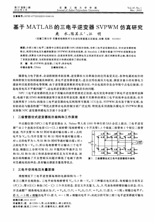
拓 扑结 构解 决 了开 关 管 耐 压 问题 并 降低 了 电磁 干 扰 和 对负 载 电机 的冲击 , 具有输 出谐 波含 量低 等优 点.
图 1 二极管箝位式三电平逆变器拓扑结构
2 三 电平 空 间 电压 矢 量 原 理
理想 情况 下 三 电平 逆 变 器 每 相 的 电路 结 构 与 一 个
滤 波和 交流 柔性 供 电等领域 . 由于逆 变器直 流侧采 用 电容 分压 , 中点 电流 的存 在 会导 致 中点 电位 振荡 , 引 起 电容 电压不 平衡 问题 _ ]这 也是 逆变器 应用 中普 遍存在 的 问题. 1, NP C三 电平 逆变 器 的优 点在 于其输 出的波形 更接 近正 弦波 , 电压变 化率 相较 于两 电平逆 变 器 明显 降 低, 电磁 干扰 ( MI和抑 制谐 波等方 面具 有 明显 优势 . E ) 随着 开关 频 率 的增 加 三 电平 的效 率也 在 提 高 , 开 在 关 频率 高于 1 k 0 Hz的场合 三 电平逆 变器 的 电压 利 用率 可提 高 1 左 右. VP 5/ 9 6 S WM 具有 易 于数 字 实现 、 良
若 S 一 0则 相输 出电平 0, S 若 一一 1 z相输 出电平 N , 则 由此分 析 可知三 相三 电平逆 变器就 可输 出
收 稿 日期 : 0 11 — 7 2 1 - 01
作者 简介 : 鹿
水 (9 5) 男 , 东 淄 博 人 , 士研 究 生 . 1 8一 , 山 硕
对 。点 的 电平为 0 当 S , 3和 S 4同时导 通 时输 出端 a 。 对 点 的 电平 为 一 V / , 以 每相 桥 臂 可 以 输 出 三 个 电平 2所
状态 . 根据 以上 分 析 可 知 S 、 3不 能 同 时 导通 并 且 S 1S 1 和 S 、 2和 S 3S 4的工 作 状 态恰 好 相 反 且 为 互 补 状 态. 该
基于SVPWM三相逆变器在MATLAB下的仿真研究.doc

基于SVPWM 三相逆变器在MATLAB 下的仿真研究摘要:介绍了电压空间矢量脉宽调制控制算法的基本概念; 并简要介绍了利用多种实际矢量合成所需电压矢量的方法及具体的实现算法; 最后,利用 Matlab 的 Simulink 工具箱,建立了SVPWM 逆变器的仿真模型,通过仿真波形可知,该算法是正确的,并分析了逆变器输出的交流电压和电流的谐波。
关键词:SVPWM 、Simulink 、三相逆变器0 引 言电压空间矢量脉宽调制( Space Vector PWM,SVPWM) 控制技术,也称作磁链跟踪控制技术,它是从控制交流电动机的角度出发,最终目的是在电动机气隙空间形成旋转磁场,从而产生恒定的电磁转矩。
空间矢量脉宽调制方法依附其优越的性能指标、易于数字化实现等优点,自提出以来就成为研究的热点,不仅可以应用在各种交流电气传动系统中,而且在电力系统功率因数的调节以及各种利用清洁能源发电的分布式发电系统中都有很好的应用前景。
1 SVPWM 逆变器的原理1.1 电压空间矢量电压空间矢量是研究交流电动机三相电压与电动机旋转磁场关系而提出的虚构物理量。
在空间按 120°对称分布的三相电机定子绕组上施加三相对称电压()1)32sin()32sin(sin ⎪⎪⎪⎭⎪⎪⎪⎬⎫+=-==πωπωωt U u t U u t U u m c m b m a在定子绕组中即产生定子电流和磁通。
对单个绕组而言,产生的磁通是脉振的,它仅在固定的绕组轴线位置上有大小和方向的变化,但是在三相绕组的配合作用下,在电机的气隙中就产生了合成的旋转磁场。
电压和电流是时间变量,并没有空间的概念,但是电动机三相绕组产生的旋转磁场是空间和时间的变量,它的大小和空间位置随时间变化,一般以矢量表示。
时空变化的旋转磁场由三相电压产生,为了描述三相电压与电动机旋转磁场的关系,提出了电压空间矢量的概念。
电压空间矢量反映了三相电压综合作用的效果,三相电压与电压空间矢量的关系由 Park 变换来表示:)2()(322401200 j C j B j S e u e u e u u A ++=式中,u s 为电压空间矢量,u A 、u B 、u C 为三相相电压,2/3为变换系数,指数项表示了三相绕组的空间位置。
用MATLAB 仿真SVPWM模块
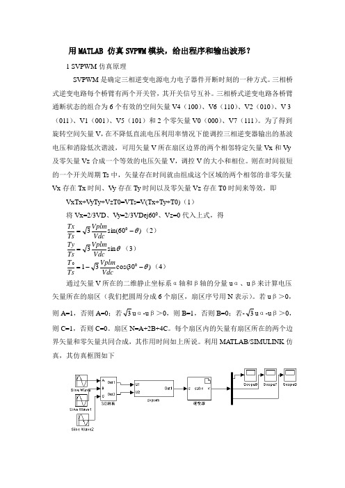
用MATLAB 仿真SVPWM 模块,给出程序和输出波形?1 SVPWM 仿真原理SVPWM 是确定三相逆变电源电力电子器件开断时刻的一种方式。
三相桥式逆变电路每个桥臂有两个开关管,其开关信号互补。
三相桥式逆变电路各桥臂通断状态的组合为6个有效的空间矢量V4(100)、V6(110)、V2(010)、V 3(011)、V1(001)、V5(101)和2个零矢量V0(000)、V7(111)。
为了得到旋转空间矢量V ,在不降低直流电压利用率情况下能调控三相逆变器输出的基波电压和消除低次谐波,可用矢量V 所在扇区边界的两个相邻特定矢量Vx 和Vy 及零矢量Vz 合成一个等效的电压矢量V ,调控V 的大小和相位。
则在时间很短的一个开关周期Ts 中,矢量存在时间就由组成这个区域的两个相邻的非零矢量Vx 存在Tx 时间、Vy 存在Ty 时间以及零矢量Vz 存在T0时间来等效,即VxTx+VyTy+VzT0=VTs=V(Tx+Ty+T0)(1)将Vx=2/3VD 、Vy=2/3VDej600、Vz=0代入上式,得)60sin(30θ-=VdcVplm Ts Tx (2) θsin 3VdcVplm Ts Ty =(3) )30cos(3100θ--=VdcVplm Ts T (4) 通过矢量V 所在的二维静止坐标系α轴和β轴的分量u α、u β来计算电压矢量所在的扇区(我们把圆周分成6个扇区,扇区序号用N 表示)。
若u β>0,则A=1,否则A=0;若3u α-u β>0,则B=1,否则B=0;若-3u α-u β>0,则C=1,否则C=0。
扇区N=A+2B+4C 。
每个扇区内的矢量有扇区所在的两个边界矢量和零矢量共同合成,其作用时间如上所说。
利用MATLAB/SIMULINK 仿真,其仿真框图如下图3.1 基于SVPWM逆变器仿真框图图3.1中SVPWM模块为根据空间矢量控制方法确定电力电子器件开关时刻模块。
- 1、下载文档前请自行甄别文档内容的完整性,平台不提供额外的编辑、内容补充、找答案等附加服务。
- 2、"仅部分预览"的文档,不可在线预览部分如存在完整性等问题,可反馈申请退款(可完整预览的文档不适用该条件!)。
- 3、如文档侵犯您的权益,请联系客服反馈,我们会尽快为您处理(人工客服工作时间:9:00-18:30)。
In this paper, a simple SVPWM method for three-level inverter is proposed. By using this method out of six sectors and twenty four corresponding regions and dwell time calculations for one sector i.e. of four regions is required and same be applied to other regions of remaining sectors just by rotating it by sixty degrees to get in other sector. And the same principal of the method can apply for other types of multilevel inverter like flying capacitor and cascaded. This technique is simulated for passive as well as motor load and open loop v/f speed control of induction motor is also done to enhance the validity of the scheme.
sector and hence seventy two dwell time calculations of six
978-1-4244-2800-7/09/$25.00 ©2009 IEEE
3388
ICIEA 2009
sectors are required. In [9] not all the dwell times are required but still more computations required and the method is not simple. Here less computations required and stress been given to prove the application to motor load and hence validity of the method is not strongly proved [9]
ON
ON
OFF
OFF
+E
O[0]
OFF
ON
ON
OFF
0
N[-1]
OFF
OFF
ON
ON
-E
(X= U, V, or W)
the three level topology is increasingly employed in flexible
AC transmission (FACTS)System such as, SVC (Static Var
technique is an advanced, computations intensive PWM
technique and is possibly the best among allrive applications. Because of its superior
Fig.1. Schematic diagram of a three-level inverter connected to load
TABLE I
SWITCHING STATES OF ATHREE LEVEL INVERTER
Switching States
S1X
S2X
S3X
S4X
VXO
P[1]
Nagpur,India mrenge@
Abstract-Advances in power electronics technology allowed the vide investigation of multilevel converters that provide high safety voltages with less harmonic components compared to the two-level structures .Because of prominent advantages like more utilization of input voltage, flexibility in switching the legs of three phase inverters and easy method of improving spectral performance and easy digital implantation, space vector modulation (SVPWM) has become the most popular technique for three phase voltage source converters for the control of ac/dc drives and Flexible ac transmission application(FACT) controllers.
Compensator), STATCOM (Static Compensator) etc. [3]
To control multilevel inverters the pulse width modulation
(PWM) strategies are the most effective, especially the space
A Simplified Space -Vector PWM for Three Level Inverters Applied to Passive and Motor Load
P. M. Meshram
Departmentt of Electrical Engg. Yeshwantrao Chavan College of Engg.,
Nagpur,India praful_1087@
Dipesh Hanote
Reliance Energy Ltd. Mumbai,India
dipesh.hanote@
M. M. Renge
Department of Electrical Engg Priiyadarshni College of Engg.
vector pulse width modulation (SVPWM) one, which has
equally divided zero voltage vectors describing a lower
harmonic distortion (THD) [4]. The space vector modulation
But implementation of space vector modulation (SVPWM) for more than two levels is difficult because for them no. of switching states is very high. In this paper simplified method is proposed in which timing calculation is required for only one sector and therefore calculations are tremendously reduced and the same could be applied to different types of multilevel inverters like flying capacitor and cascaded. To check the validity of the scheme, simulations are done for passive(R-L) load and motor load. Open loop V/f speed control method of Induction motor is also done to enhance the validity of the scheme
performance characteristics, it is been finding wide spread